Pages

Saturday, June 28, 2014

Progress Report 53

Some interesting developments this month: for various reasons, not least a two week holiday in rural France, there has been little opportunity to have any proper operating sessions, but there has been plenty of activity in the workshop.

Manning Wardle 0-6-0ST loco build

With full approval from my other half, I usually take some modelling materials with me to France and engage in some prime time modelling - literally on the kitchen table with the bare minimum of tools - a steel rule, a craft knife and a set of needle files.

This year, I took the plan of a Davington Light Railway Manning Wardle 0-6-0 saddle tank locomotive with me and spent my time doing the basic groundwork of producing the body. Before leaving, I cut out the running plate and figured out how it would sit on the Piko motor block.

This then formed the basis for the next stage of the build. By the end of the holiday, I had made the cab and fixed this to the footplate as one unit.

I had also completed the boiler, tank, firebox and smokebox as a separate unit to simplify the painting process on my return to Blighty.

The next stage will be to add fine detailing to the bodywork and to construct the motion. I will also have to figure out where to locate the batteries and the radio control gear. The easiest solution would be to put everything in a trail car, but as I do a lot of shunting and run round trains at each terminus, I need to have each loco fully self contained. Despite its generous overall size, the saddle tank restricts the amount of usable internal space available. Locos with side tanks are far more obliging in the provision of workable space for radio controlled battery power (see How I constructed a Manning Wardle 0-6-0ST loco - pending).


Remote control for signals

After my success with using a Picaxe controller circuit for the remote control of my LGB point motors (see Progress Report 52), I was keen to find a way of using servos to control my semaphore signals (see How I made 19 semaphore signals).

Fortunately, a fellow modeller had produced an impressive Picaxe program to realistically replicate the bouncing action of a signal (see Comparing two equations for signal control). The circuitry for wiring the outputs from the controller board to the servos was fairly straightforward and I linked the inputs to a very cost effective keyfob operated 4 channel receiver and transmitter.


As I have four signals at each station, this set-up will prove to be ideal for my needs. I still have to work out how I will power the receivers and servos at each station and organise the wiring for each signal. Also, I am uncertain as to the maximum length the servo leads can be to prevent significant loss of signal, but so far this seems to be a cost effective and effective means of controlling my signals.


Still plenty to do and with some fine weather forecast it might be that the lure of the garden beckons. After all, playing running trains is what this hobby is all about!


Tuesday, June 10, 2014

How I made some noticeboards

Having found or created posters, timetables and notices and printed them out (see How I created period posters, enamel signs and notices), I decided that some of them needed to be mounted on noticeboards.

A piece of 1.2mm (50thou) thick black plasticard was trimmed roughly to the size of the poster, plus 3-4mm on each edge.

3mm wide strips of 1.4mm (55thou) thick black plasticard were then glued to the edges using liquid poly adhesive. The strips were deliberately cut to be longer than needed and overlapped at the corners (but not glued).

When the glue had set sufficiently to grab the strips, a craft knife was positioned diagonally across the overlapping strips at the corners and pressure applied to cut through both strips.

This helped to ensure that the mitres for the corners matched exactly. Liquid poly glue was then flooded into the corners with a paintbrush and left to set.

The frames were then rubbed-down with fine abrasive paper before being given a couple of coats of acrylic paint. The virtue of using black plasticard is that the insides of the frame do not need to be painted. As can be seen from the photo below, some of my edging strips were not quite 3mm in width, I'm sure those who have more precise cutting skills than me (or those who purchase microstrip) will do a better job.
I've found in the past that a light coating of matt or semi-matt varnish prolongs the life of the posters, however, even with this precaution, it seems that slugs and snails enjoy feasting on any form of paper and so, from this year onwards, I am tending to remove my buildings from the garden when I know the railway is not going to be used for a few days.

Progress Report 52

The weather has been very mixed since the previous update (See Progress Report 51). There have been a few days of sunshine but mostly the weather has been showery, which is the worst type of weather for playing trains - no sooner have I put out equipment than I have to gather it up, trying to decide if it will be a short sharp shower or a more prolonged downpour. Fortunately, with radio control and battery power, I have been able to run the odd train now and again. However, I have managed to get one full running session in, and the wet weather has given an opportunity for several indoor projects to get completed.


A Day in the Life of Peckforton Station

During the full operating session, I set up my video camera at Peckforton Station and, each time a train passed through, filmed its progress. The result is a video showing a typical day in the life of one station on the line. The video has condensed the day into a series of brief episodes, but the feedback from fellow modellers has been encouraging.

In addition, I took a series of stills from the video sequences, and produced a blog posting outlining the day's activities. (See A Day in the Life of Peckforton Station)

Track sweeper

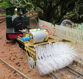
Although track cleaning is no longer the pain in the butt which it used to be, locos and stock can still be derailed by the dreaded 'leaves on the line' and other debris.  I've discovered, for example, that from time to time, blackbirds and thrushes like to use the rails as anvils to crack open snail shells. Whilst, I still have to cut back the vegetation (on a weekly basis at the moment), it's still necessary to check the track before each running session - even one twig can have disastrous consequences. To help this tidying-up process, I have produced a simple track sweeper which can be sent around the track before a running session to remove the general detritus which the track seems to accumulate. (See How I constructed a track sweeper)

Take one HLW wagon chassis, a couple of pieces of brass rail, some brass strip, a motor, battery and a bottle brush and voila!


Trestle Bridge

In the previous Progress Report (see Progress Report 51), I gave an account of the building of the mill siding. The track crossing the stream had been left hanging in mid-air, awaiting the construction of a suitable bridge.This has now been completed (see How I constructed a small wooden trestle bridge), based (loosely) on the wooden trestle bridge which was situated on the Southwold Railway beside the water mill between Halesworth and Wenhaston.

At the moment, the bridge looks very new, but now it has taken up permanent residence, it will weather naturally.

Flat wagons

Adding details to the match truck

Following suggestions from fellow modellers on the G Scale Central forum, I've added a few more details to the match truck which will accompany the mobile crane whenever it ventures forth.

The detailing includes a couple of baulks of timber, a coil of rope, some chain and various other utilitarian objects such as a tool kit and re-railing jacks. I may distress and weather the wagon still further as it would be likely to suffer considerable abuse as it goes about its duties on the railway.

A new permanent way wagon

I decided that, rather than making the above wagon a general purpose Engineering Department wagon, I would make another flat wagon more specific to platelaying to be towed behind the IP Engineering Lollypop Railcar (see How I constructed an IP Engineering railcar) which I have designated as an platelayers' trolley.

The flat wagon uses an IP Engineering Hudson wagon chassis as its basis, with a coffee-stirrer body and tools provided by Bachmann. It needed to be small in size to match the dimensions of the railcar, and looks appropriate as it trundles around the railway (see How I constructed a small flat wagon).

Points controller

Having decided to move over from DCC controlled track-power to radio controlled battery power, one of the sacrifices was going to be the remote control of some of my pointwork from the DCC remote handset. Casting around for alternatives, I discovered the Deltang points and accessories controller which has seven outputs. As I had six turnouts which needed to be controlled remotely (owing to their awkward locations), this seemed to be the most appropriate solution. However, the controller is designed to work with r/c servos rather than LGB point motors and so I was faced with the dilemma of either replacing all the existing LGB point motors with servos, or finding some way of adapting the Deltang controller so it would operate the LGB point motors.

 Following the guidance of a fellow garden railway modeller (who, incidentally is based in Australia), I programmed a Picaxe microprocessor to respond to the Deltang receiver and generate a half second pulse of electricity to kick the relevant LGB points motor into operation.

It was surprisingly easy (and equally surprisingly inexpensive), to construct a system which would operate relays in response to the instructions generated by the microprocessor. I can now control my more inaccessible pointwork by the flick of a switch.

Wiring-up the most distant turnout

The most distant point (on the approach to the swing bridge) had not been hard-wired - it used a slot-in decoder connected directly to the track. This needed to be connected to the points controller, situated in the outhouse about 40m away. I happened to notice a couple of lengths of orange mains cable which my neighbours had thrown away in a skip which they no longer needed. This was pressed into service, routed around the outside of the garden and then buried.

Station Buildings

Until now, I have left my station buildings outside throughout the year and, even though they are constructed from resin castings or plastic (see How I constructed some station buildings and How I constructed a station building from a toy, they were beginning to show signs of wear and tear. Some of the epoxied joints had sprung apart and the paintwork was beginning to peel in places see Progress Report 50).

The buildings were brought inside and all the internal joints (regardless of whether they had failed) were reinforced with a strong instant-grab, flexible adhesive.

The representations of timber framing were repainted green and some of the roofs were touched-up but I decided to leave the cream clapperboard as it was as this was generally surviving well (it was watered-down masonry paint designed for outdoor use with a ten year guarantee). The posters and signs were all reprinted and re-applied (see How I made some period posters and enamel signs). Some posters were mounted on noticeboards, made from black plasticard (see How I made some noticeboards)


I have decided to bring my buildings inside during the winter months from now on to prolong their working lives (and to save myself unnecessary maintenance).
The station buildings and platform paraphernalia ready to be installed in the garden
Peckforton Station building in situ
Beeston Market Station building


Platform detailing

Whilst re-installing the buildings, I decided to assemble and paint various kits and general clutter of platform equipment which I had accumulated, such as trolleys, firebuckets, seating, luggage, etc.

These items had come from various sources including Trenarren Models, Garden Railway Specialists, Roundhouse, Modeltown and Back2Bay6.

These items were constructed and then given a couple of coats of primer, before being given a final coat of green or red, with detailing added with acrylics.

As time progresses, I will add more and more items of this sort as it seems to me that this type of detailing is what brings a railway to life.

Sunday, June 01, 2014

How I made a small Permanent Way wagon

After completing the IP Engineering Lollypop Railcar kit (see How I constructed an IP Engineering Lollypop Railcar), and fitting it out with batteries and Deltang radio control (see Deltang radio control - an evaluation), I felt it needed some sort of trailer to enable the crew to carry their equipment. The flat wagons which I had constructed previously, were too large (see How I constructed some flat wagons) and so I cast about for something suitable. I noticed on the IP Engineering website that there were some Hudson wagon chassis, one of which I thought might be suitable and so, after parting with my hard-earned dosh, I received the kit.

The kit is extremely straightforward to construct - after cleaning the castings, the four axle boxes were epoxied to the frame with the axles installed.

While the glue was setting, ten coffee-stirrers were cut to a length of 90mm .......

...... and another four were cut to a length of 51mm.

Two of the shorter planks were placed across the chassis frame and coated with PVA adhesive.

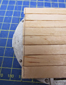
Eight of the longer planks were then glued to these cross members. When the glue had dried, the ends of the planks were marked and trimmed with a craft knife to even off their lengths.

The remaining four planks were  trimmed to length and glued around the edges of the platform, ......

..... and a couple of spacers were trimmed and inserted between the sides. Then everything was held in place with an elastic band until the glue set.

In the meantime, a strip of 0.2mm thick brass was marked out to the width of a coffee-stirrer (7mm), and then cut-out with tin-snips.

These were then snipped into 14mm lengths and six depressions were punched into them with an automatic centre punch tool, to represent rivet heads.

These corner plates were then marked across their centres and folded to 90 degrees by applying pressure along the centre-line with a  craft knife.

Some of the plates needed to be flattened with pointed-nose pliers ......

.......... before being superglued on to the corners of the wagon body.

The wheels of the chassis were masked with masking tape before the chassis and the body were given a couple of coats of Halford's grey primer from an aerosol rattle-can.

Once the primer had dried, the corner plates were picked-out with black acrylic paint.

The chassis was given a couple of coats of satin black from a spray can before the masking tape was removed. The body was then given a light wash of mucky brown and black acrylics, and the chassis daubed with various shades of brown acrylic to represent rust. The body was then fixed to the chassis with superglue.

 A set of Bachmann tools had been purchased .......

....... and then dulled-down and dirtied with acrylics. These were then superglued on to the wagon body in what I hope looks like a random but workmanlike manner.

 The wagon was then coupled to the Lollypop railcar and given a test-run (or several).

To my mind, the wagon gives the impression of a home-built utilitarian truck such as those which a permanent-way gang might have constructed for their own use. It maybe needs a little more battering and abuse, and the railcar could do with some weathering to suggest more wear and tear, but overall, this little addition to the stock list seems to fit the bill.