My first scratchbuilt loco was a diesel mechanical loco based on a cross between a standard gauge and a 2' gauge Fowler loco (see How I constructed an early Fowler diesel locomotive). I had been unable to find a 3' gauge Fowler and so surmised it would look similar to their standard gauge locos - albeit smaller.
When I changed from DCC track power to battery powered radio control, I constructed several locos to be purely battery powered and slowly converted my previously track powered locos to battery power. This particular loco had been sitting on the shelf, awaiting conversion to battery power, for around two years. Her duties were being discharged by my IP Engineering Jessie (Loco No. 8, Wynford) and so there was no immediate need for Tollemache's conversion. I kept putting it off as I knew I'd have to sort out the flycranks which had been a problem during construction. Ultimately, the solution of this problem was a lot easier than I expected (see How I increased the offset of some GRS whitemetal flycranks).
With this problem solved, the path was paved for the loco's conversion to battery power.
The LGB ToyTrain 0-4-0 motor block was separated from the body and taken apart to remove the wheel and track electrical pickups. I have described this process previously (see How I converted my GRS Peckett to battery power).
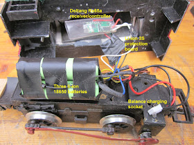
To create space in the engine compartment of the loco, I had to remove the lead flashing to accommodate the three tagged 18650 li-ion batteries which were soldered together in series to provide the 11.1 volts power supply.
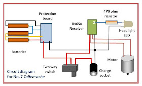
This battery pack was then connected to a li-ion battery protection board (see circuit diagram below) which had been bought from China via eBay ......
A 3S balance charge socket was also soldered into the circuit to allow the charge levels in the individual cells to be measured.
The charge socket and two-way switch were wired-up with connections to the output terminals on the protection board.
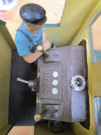
The switch and socket were then installed in holes drilled in the instrument panel of the loco cab.
The positive input lead to the Deltang Rx65a was then connected to the switch and the negative lead to the supply contact on the protection board. A lead was also soldered to Pad 2 on the receiver board. This is the output for the rear directional light (my locos are all reverse wired for directional lighting because the first locos I wired-up were all accidentally reverse wired). This lead was then connected to the headlamp LED.
The incandescent bulb in the headlamp was removed and a bright white LED inserted into the socket (this was actually the most difficult and time consuming stage of the conversion). A 470ohm resistor was then wired into the supply lead for the LED before being connected to the output from the board. The other lead from the LED was connected to the negative terminal on the protection board.
The wiring was then tested by turning on the power switch and binding the receiver to the Tx22 transmitter. The circuit boards and batteries were then insulated with insulation tape to avoid accidental short circuits when the components were squeezed into the engine compartment.
After test-fitting the components, I realised there was some available space to re-instal some of the lead flashing. This was trimmed to size and glued to the sides and roof of the engine compartment with clear Bostik adhesive.
To summarise, the circuit diagram for the conversion indicates how the components were connected. The four leads for the balance charge socket were soldered to the four connections for the batteries on the protection board making sure the order of connections to the batteries was preserved (from positive (red lead) to negative (final black lead)).
The loco was reassembled ..........
...... and then given a few test runs.
Although she has quite good hauling power (as can be seen from the video), I would like to install a little more weight as there is some wheel spin on my 1:40 gradients when hauling a full load. It might be possible to install a couple more pieces of lead flashing in the engine compartment but I will probably also find a few nooks and crannies to add a few more pieces of lead.
Overall, I am delighted to have this loco back in service. She has now been fully recharged and seems to be very controllable. For now, I feel I have sufficient locos to run services on my railway - but who knows whether I might see another prototype which seizes my attention??


No comments:
Post a Comment