Contents
Introduction
Having just finished detailing the interiors of my Leek and Manifold Railway (ish) coaches (see How I made interiors for my coaches) and modified some figures to sit inside them (see How I modified some cheap figures for the 1930s), I thought it might be opportune to install some lighting in them. I thought of various ways it could be done such as using a bus-bar as I had done on my Ford(ish) railcar (see How I bashed some Andel coaches into a railcar). However, some time ago I had bought some lighting boards cheaply on eBay which were supposed to work off track power, so I decided to use these as the basis for my lighting circuitry.Preparing the lighting strips
The first job was to remove all the components from the perforated boards. For some reason, the LEDs were wired in series and so, as I wanted to run them from a 3v supply, I needed to rewire them. The components (ie rectifier, voltage regulator, capacitor) were redundant and so were relegated to the spares box.The LEDs were wired in parallel and trailing leads added to one end.
I now needed to decide on which batteries I would use and how the lighting would be switched on and off
Batteries and switches
Option 1 - Alkaline batteries and manual switch
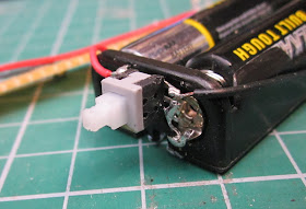
My first idea was to keep things very simple. Power the lights with two AAA alkaline batteries and switch them on and off with a latching push-button switch.The lighting strips were fixed under the roof with BluTak and the switch contacts were soldered directly to the contacts on the battery box.
The battery box was then attached to the underside of the roof with BluTak.
NOTE: Subsequently, I discovered that when the sun shone (a rare occurrence in this part of the world), the BluTak softened and was insufficient to hold the battery box in place, and so the BluTak was replaced with Gaffa Tape.
Of course, this meant the roof had to be removed each time I wanted to turn the lights on or off, but it also meant that, as all the wiring was attached only to the roof section, there were no trailing wires between the roof and the rest of the coach body.
However,I was not entirely happy with this arrangement. Although I fixed the rood in place with magnets to make it easily removable, I wanted some way of turning the lights on and off without having to remove the roof each time. The magnets gave me an idea.
Option 2 - Latching reed switch and alkaline batteries
As I did not want the switch to be visible on the roof, and I didn't want wires leading down from the roof to the body of the coach, I needed a method of operating the lights remotely. Radio control was an option, but expensive, whereas reed switches could be triggered with a magnet. However, reed switches only provide momentary switching so I searched the internet for simple electronic circuit which would provide latching on/off switching. There were some available, but these were quite complicated affairs - I much prefer the simple (and cheap!).My mate, Greg, in Australia drew my attention to some very cheap electronic modules which provided latching outputs from a momentary trigger.
At just over £1.00 each (including postage), they were a lot cheaper than I could make from discrete components - and so I sent off for a few.
There were other versions available and I also considered latching Hall Effect integrated circuit chips, but the residual current drain (ie how much current they consume when 'off') was 60uA, whereas the residual current drain on these modules is 'less than 2uA, according the blurb on the eBay page.
When they arrived (by slow boat, it seemed), I wired one up on a small piece of Veroboard with a reed switch connected between the 0v and Trigger inputs.
This was then connected to the battery box and the lights.
The wiring is minimal - the Veroboard is not essential but, as reed switches are very delicate, I wanted to provide some sort of protection against accidental damage.
In the coaches, there are six LEDs wired in parallel, but these have been omitted for clarity.
Option 3 - Magnetically operated switch with a 3.7v rechargeable li-ion cell
For the third (brake end) coach, I decided to explore the feasibility of using a rechargeable 3.7v li-ion cell. I made up a small circuit board as above, but included a 2A polyswitch to protect against accidental sort circuits.This was wired-in between the positive lead from the li-ion cell and the +ve input leg of the flip flip module.
However, I realised I also needed to include a 1S li-ion battery protection board in the circuit, to protect the li-ion battery from becoming over-discharged. Li-ion batteries must never fall below a charge of 2.7v otherwise they become permanently damaged and so some form of electronic protection needs to be included to prevent this from happening.
A 1S protection board was acquired (via eBay) and wired-up - two leads to the li-ion cell and two leads to the flop flop module board.
The cell and protection board were then wired-up with the module and LED boards.
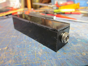
Once everything had been tested, I made a box for the li-ion cell from black 1.5mm plasticard .....
A 2.1mm DC socket was included in one end of the box ........
....... so it could be used to recharge the battery. All the leads and the battery protection circuit board were shrouded in heatshrink sleeving to help avoid accidental short circuits.
The battery box was assembled .......
...... and then wired back into the main circuit,
....... and the leads from it connected to the rest of the circuitry with a 2 pole micro JST connector ......
..... enabling the roof to be removed completely if the need should arise.
Conclusion
In all three coaches, the lights are now switched on and off by waving a magnet over the coach roofs.The reed switches have proven to be very sensitive and the magnet needs only to be waved in its general vicinity for the lights to come on (see video below).
I may increase the value of the resistor in the LED circuits, to reduce the current to the lamps. In the dark, they seem to be a lot brighter than the lighting which would have been available in the original coaches. This will have the added advantage of increasing the 'life' of the batteries before needing replacement or recharging.
I will be interested to find out how long the batteries do last. I imagine they will last longer than a year given that the current drain on them is so low. However, field-testing will enable me to put a more definitive figure on that. In the meantime, I am very pleased with how the coaches look - I now need to consider ways of lighting the station buildings and platforms as I now have good reason to run night trains.


Excellent description. Is the polyswitch essential? I must read up on them and the lion protection.
ReplyDeleteNot essential as the protection board will respond to short circuits. It's really just an extra precaution - I tend to use a belt and braces approach when wiring li-ion batteries into a circuit.
ReplyDeleteI notice you did not connect the +ve voltage to pins 1 and 2 and the load to pins 4 and 5 as per the giudance for this IC. Did that present any problems?
ReplyDeleteI have connected all pins and there is a low leakage resulting in the LEd not going fully out.
David
Hi David
ReplyDeleteNot sure what you mean by 'load' to pin 5. This is the trigger for the Vo on pins 3 or 4. My understanding was that pins 1 and 2 are interchangeable and so only one or the other need to be connected to the supply voltage.
I get very little leakage. After two years, the batteries are still sufficiently charged to for the LEDs.
Rik
I had a LED connected to pin 5 via a resistor. Initially worked but leakage kept LED just lit when should be out. Now it has decided to stop working - so not impressed with the IC
ReplyDeleteDavid
Hi David
ReplyDeleteThe LEDs should be connected to pin 4, the trigger connects to pin 5
Rik