
Introduction
Ten years ago, after constructing 19 semaphore signals for my railway (see How I constructed 19 semaphore signals), I put some of them under radio control using a Picaxe microprocessor and a cheap keyfob transmitter (see How I radio-controlled some of my signals).
However, whilst the Picaxe programming of the signal arms movement was excellent (thanks to my mate Greg), the system as a whole was quite cumbersome. The relays on the receiver-board needed a 12v supply, for which I used a lead-acid battery, and four signals needed to be hard-wired to the receiver/controller. As I wanted to be able to remove the signals at the end of each running session, they needed weatherproof plugs and sockets and the control box either needed to be weatherproof or removable.
What I really wanted was to make each signal self-contained, so it could be easily deployed and removed - no central control-box and no trailing wires.
Over the past ten years, I have been looking-out for something which would be suitable. What I really needed was a compact, low-voltage (and cheap!) receiver, which could be housed beside or beneath each signal so when I spotted this key fob RC system on AliExpress,....

.... I was delighted. It seemed to fulfil my needs; it could operate off a
3.7v supply (ie one li-ion cell) and each of the four receivers had a small
footprint (22.5mm x 11mm) (see -
qiachip.com
)

What I needed next was an Arduino microprocessor with a similarly small
footprint. Whilst I could have used a Picaxe 8M, I would have also
needed a board on which to mount it and also some additional components. As it
turned out, a Seeeduino XIAO (21mm x 18mm) seemed to fit the bill,
especially as I had been learning Arduino coding for another project
(see
Controlling a loco with Arduino and Bluetooth). Furthermore, it could similarly operate from a 3.7v supply.


And, finally, I needed some small lithium-ion cells. Although I had a couple of AA (14500) cells to hand, I would need another 17 to power-up all the signals. A quick scan of eBay revealed that the cheapest cells were 16340s (ie 16mm diameter x 34mm long).

Although these claim to be 2800mAh, I know from experience that this needs to be taken with an enormous slab of salt. Also, for the price, I would have to treat them with extreme caution - especially when charging. However, at only around £1GBP per cell, I was willing to give them a try.
Programming
So, with the hardware now sorted-out, I now needed to figure out the Arduino coding to make it work.
The receiver could set up to provide either a momentary 3.3v (HIGH) or a 0v (LOW) output - ideal for triggering the Seeeduino. In addition, it's relatively straightforward to provide outputs to control servos with Arduino coding.
My initial code simply sent the servo either up or down, with an output on Pin 6 dependent on a 0v (LOW) triggering signal on Pin 0.
#include <servo.h> //Loads the servo command library
Servo myservo; //Names the servo "myservo"


//variables
int sigstate=0; //Flags the state of the signal (1 = raised 0 = lowered)

void setup() { //The inital set-up procedure
 myservo.attach(6); //Attaches myservo to Pin 6
 myservo.write(0); //Sends myservo to 0 degrees
 pinMode(0,INPUT_PULLUP);//Sets Pin 0 to input and sets it initially to HIGH
} //End of the setup procedure

void loop() { //The main loop procedure
  if (sigstate==0){ //Checks the signal state - If lowered (ie sigstate 0) .....
    raiseit(); // .... it raises the signal
    sigstate=1; // and sets the sigstate to raised (ie 1)
    delay (500); // Pauses half a second
  }
else { //If the signal is already raised ......
  lowerit(); // .... the signal is lowered
  sigstate=0; // and sets the sigstate flag to 0
  delay (500); // then waits half a second
}
} //End of the main loop

void raiseit(){ //The raise sub procedure
myservo.write(180); // Sends the servo to 180 degrees
}

void lowerit(){ //The lower sub procedure
myservo.write(0); // Sends the servo to 0 degrees
}
Having satisfied myself that the hardware was performing as it should, I increased the sophistication of the programming to move the signal arms more slowly and include some sort of bounce at the end of each movement.
#include <Servo.h> //Loads the servo command library
Servo myservo; //Names the servo


//variables
int sigstate=1; //Logs the state of the signal arm (1=raised, 0=lowered)
int val; //Used to record the state of the triggering input from the receiver
int x=0; //Used in For..... loops
float y; //Allows for variable y to have a floating decimal value
int z; //Also used in For.... loops

void setup() { //Initialising instructions
 myservo.attach(6); //Connects a servo output to Pin 6
 myservo.write(140); //Sends the servo to 40 degrees (ie raised)
 pinMode(0,INPUT_PULLUP); //Sets pin 0 to HIGH by default
} //End of initialising

void loop() { //Main program loop
val=digitalRead(0); //Checks the input from the receiver on pin 0
if (val==0) { //If pin 0 has gone LOW (ie if it has received input from the rx)
  if (sigstate==0){ // ..... and if the signal is already lowered .....
    raiseit(); //... then go to the sub procedure to raise the signal
    sigstate=1; //... and set the signal state flag to raised
    delay (500); //Wait half a second
  }
else { //Alternatively, if the signal state is already raised ....
  lowerit(); //... then call the lowering sub procedure....
  sigstate=0; //.... and set the sigstate flag to lowered.
  delay (500); //Pause for half a second
}
}
}//End of Main program loop

void raiseit(){ //Start of the raising sub procedure
  x=40; //Sets the value of x to 40 (the lowered position of the servo)
  do {
    delay (10);
    myservo.write(x); //Move the servo to the value of x
    x++; //Increase x by 1
  } while (x<140); //Carry on doing the above while x is less than 140 (the upper position of the servo)

for(z=140;z>120;z--) { //The first bounce .....
  myservo.write(z);
  delay(10);
}
for (z=120;z<140;z++){ //.... and back again
  myservo.write(z);
  delay(5);
}
for(z=140;z>130;z--) { //Second (lesser) bounce .....
  myservo.write(z);
  delay(10);
}
for (z=130;z<140;z++){ //.... and back again.
  myservo.write(z);
  delay(5);
}
  myservo.write(140); //Makes sure the signal is raised
}//End of the raising sub procedure

void lowerit(){ //Start of the lowering sub procedure
  x=100; //Sets x to 100
  y=1; // and y to 1
  z=140; // and z to 140 (the raised position of the servo)
do {
  myservo.write(z); //Sends the servo to z degrees
  delay(x); //Waits for x milliseconds
  x=x-y; //Reduces x by the value of y
  if (x<0){x=5;} //Makes sure x doesn't become negative
  y=y+0.5; //Exponentially increases the value of y (it gets larger increasingly faster)
  z--; //Decreases the value of z by 1 (ie the position of the servo by 1 degree)
} while (z>40); //Do the above until z reaches the lowered value for the servo

for(z=40;z<60;z++) { //First bounce ......
  myservo.write(z);
  delay(5);
}
for (z=60;z>40;z--){ //..... and back again
  myservo.write(z);
  delay(5);
}
for(z=40;z<50;z++) { //Second (lesser) bounce ......
  myservo.write(z);
  delay(5);
}
for (z=50;z>40;z--){ //.... and back again
  myservo.write(z);
  delay(5);
}
} //End of the lowering sub procedure
This code was tested and seemed to work quite well, though the bounces needed a bit more tweaking.
Before working on improving the base, I decided to add another feature - the ability to turn on and off the signal lamp by holding down the button on the transmitter for more than two seconds. I consulted various online sources, but wasn't entirely sure how to incorporate the code into my simple procedure, and so asked ChatGPT to lend a hand. I was pleasantly surprised by the result. The code was very well written, with copious explanatory comments and notes. I can thoroughly recommend using ChatGPT to assist with Arduino programming - but the instructions you give it need to be very precise. For example - https://chatgpt.com/share/219dc577-5a3e-4659-86fc-83adb1a66580
Armed with the additional information provided by ChatGPT, I modified the coding to include the LED switching capability.
#include <servo.h> //Loads the servo command library
Servo myservo; //Creates a name for the servo

//variables
bool sigstate=1;//1 = signal raised, 0 = signal lowered
int val; //Val used to record when trigger is received from receiver
int x=0; //Variable used in various for.... loops
int z; //Ditto
int uplim=150; //Upper limit for servo (in degrees 0-180) - Change if necessary
int lowlim=50; //Lower limit for servo - Change if necessary
float y; //Variable used to count milliseconds when input is triggered from receiver
bool ledState = true;     // Variable to store the current state of the LED - initally set to ON
unsigned long triggerStartTime = 0;  // Variable to store the time when trigger pin was first held low
unsigned long triggerEndTime = 0; //As above but stores when trigger signal is no longer low

//Constants
int trigpin=0; //Arduino pin used for trigger input from receiver
int sigpin=6; //Pin used for servo output
int ledpin=3; //Pin used for LED output
const unsigned long holdTime = 2000;  // Time in milliseconds that the pin must be held low

void setup() { //Initialising instructions
 myservo.attach(sigpin); //Tells Arduino the pin used for the servo
 myservo.write(uplim); //Sets the servo to its upper limit for the start of the session
 pinMode(trigpin,INPUT_PULLUP); //Defaults the trigger input to HIGH
 pinMode (ledpin,OUTPUT); //Sets the LED pin to output mode
 digitalWrite(ledpin, ledState);  // Sets the initial state of the LED
} //End of initialising instructions

void loop() { //Start of main program loop
   if (digitalRead(trigpin) == LOW) { //Checks the state of the trigger input to start measuring the time it is help LOW
    if (triggerStartTime == 0) { //
      triggerStartTime = millis();  // Record the time when pin 0 is first held low
    }

    do {
      triggerEndTime=millis(); //Records the time when the trigger input is no longer LOW
   }while (digitalRead(trigpin)==LOW);
       if (triggerEndTime - triggerStartTime >= holdTime) { // Check if pin 0 has been held low for the required time
      ledState = !ledState;               // If so, toggle the LED state (LOW to HIGH or vice versa)
      digitalWrite(ledpin, ledState); //Turns on or off the LED
      triggerStartTime = 0;
      triggerEndTime =0;      // Resets the timers
    }

  else { //If the trigger isn't held LOW for the required time, then .....
    triggerStartTime = 0; // Resets the timers
    triggerEndTime =0;
 if (sigstate==1){ //Checks if signal is raised
    lowerit(); //If so, jumps to the signal lowering sub procedure
    sigstate=0; //Updates the flag showing the state of the signal
    delay (500); //Waits for half a second
  }
else { //So, if the signal isn't raised .....
  raiseit(); //Jumps to the signal raising sub procedure
  sigstate=1; //Updates the flag to show the signal is raised
  delay (500); //Waits for half a second
}
}
}
} //End of main program loop

void raiseit(){ //Start of signal raising sub routine
  x=lowlim; //Start off at the lower limit for the signal
  do {
    delay (10); //Wait 10 milliseconds
    myservo.write(x); //Set the position of the servo to x degrees
    x++; //Increase x by 1
  } while (x<uplim); //Keeps doing the above until the upper limit is reached

for(z=uplim;z>uplim-30;z--) { //First bounce
  myservo.write(z);
  delay(10);
}
for (z=uplim-30;z<uplim;z++){ //Return to upper limit position
  myservo.write(z);
  delay(5);
}
for(z=uplim;z>uplim-20;z--) { //Second bounce
  myservo.write(z);
  delay(10);
}
for (z=uplim-20;z<uplim;z++){ //Return to upper limit position
  myservo.write(z);
  delay(5);
}
  myservo.write(uplim);
} //End of raising sub routine

void lowerit(){ //Start of lowering sub routine
  x=100; //Initial value for delay in dropping the signal arm (slow to begin)
  y=1; //Start of how much the delay is decreased
  z=uplim; //Initial value for position of servo
do {
  myservo.write(z); //Sets the servo to z degrees
  delay(x); //Pauses x milliseconds
  x=x-y; //Decreases the pasue time by y seconds
  if (x<0){x=5;} //Makes sure the pause doesn't become negative
  y=y+0.5; //Exponentially increases the reduction in the pause between each servo step (so the drop gets faster)
  z--;//Decreases the position of the servo by one degree
} while (z>lowlim); //Does all the above until the lower limit is reached

for(z=lowlim;z<lowlim+20;z++) { //First bounce
  myservo.write(z);
  delay(5);
}
for (z=lowlim+20;z>lowlim;z--){ //Return to lower limit position
  myservo.write(z);
  delay(5);
}
for(z=lowlim;z<lowlim+10;z++) { //Second bounce
  myservo.write(z);
  delay(5);
}
for (z=lowlim+10;z>lowlim;z--){ //Return to lower limit position
  myservo.write(z);
  delay(5);
}
} //End of Signal Lower sub rountine
With the hardware and software now working as intended, it was time to work on improving the signal baseplates.
Baseplates
These were designed and tweaked with my go-to 3D CAD package - TinkerCAD. It may not be the most sophisticated 3D CAD package, but it is simple to use and, so far, I've never had a file which my printers can't handle.
Once all the pieces had been printed out.....

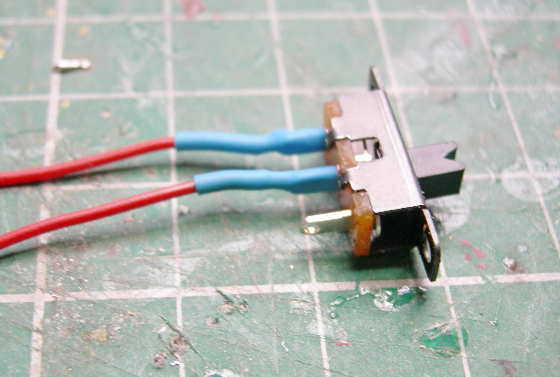
... the first task was to wire-up the SPDT sub-miniature slide switch as this would be inaccessible later.

The connections were shrouded in heatshrink tubing to avoid accidental short-circuits.
The switch was fixed into the holes provided with small self-tapping
screws.


I decided the li-ion cells would be removable for charging. As indicated above, I was concerned about their quality and reliabilty and so wanted to be able to charge the cells externally (in fact, I will charge them outdoors as an extra precaution!).
Two pieces of 30 x 8 x 0.5mm brass strip were cut, ......

...... folded in half ........

..... and one side given an extra fold at the half-way point.

These brass contacts were then glued into the slots provided.........

...... with a few dabs of superglue to hold them in place.

A 1S BMS li-ion battery protection board was given heatshrink shrouding over
its metal strip contacts ......

..... before the ends of the contacts were soldered ......

...... to the brass contacts.

The wire from the centre terminal of the slide switch was trimmed and soldered
to the P+ contact on the BMS board.


This was then inserted into the holes beneath the battery compartment in the base, as shown.


The receiver was temporarily connected to a spare li-ion cell to power
it up.


The supplied wires on the receiver..........

..... were then removed (with a soldering iron), including the aerial lead. The connecting wires are too fat for the confined space within the base and the aerial lead, as supplied, is too long.

New (thinner) wires were then soldered to the pads on the receiver, and the
aerial wire was reduced in length by around 25mm and resoldered to its pad.


The soldered connections were then shrouded in heat shrink tubing.

Pins 0, 3 and 6, and the VIN and GND terminals were tinned on the underside of the Seeeduino board,

One of the black leads was soldered to the GND terminal and a read lead
soldered to the VIN terminal.

The servo mount was prepared ........

|
.... and a servo attached to it using 1.4mm diameter self tapping screws,
........

..... which I had obtained (very cheaply) as part of a set from eBay.


The servo mount was then slotted into its housing, and.......

....... the white (signal) lead from the servo soldered to Pin 6 on the
Seeeduino board. At the same time, a yellow lead was soldered to Pin 3
(for the LED) and the brown lead from the negative output of the receiver was
soldered to Pin 0.

The red and black leads from the servo were soldered to the last remaining red
and back leads from the switch and BMS board.

The slack in the leads was then carefully taken up by routing them behind the
USB port on the Seeeduino board and coiling them in the void behind the
servo.

A 16340 li-ion cell was then inserted into the battery compartment ......

..... and the switch turned on to check whether everything was functioning as
expected - i.e., when the A button on the transmitter was pressed, the servo
responded.

So far, so good! I was now ready to attach the signal.
The correct sized socket was selected (because the base of each signal varies
slightly dependent on how well, or badly, it was planed). In the event, a
piece of 1mm thick plasticard had to be inserted to take up a small amount of
slack.

The end of the brass rod from the servo linkage was bent and inserted into the
hole in the end of the balance arm. Finding the correct length was a case of
trial and improvement. None of my signals is of a uniform design, and so some
tweaking was required. This also included tweaking the uplim and
lowlim constants in the Arduino code to fine-tune the travel of the
servo arm.

The end of the ladder was trimmed to line-up with the ends of the U shaped
copper bracket (see above) and the ends filed to remove any paint, ready for
tinning with solder.

The legs of the copper bracket were then soldered to the base of the
ladder.

The yellow lead from the LED output pin of the Seeeduino was threaded
through a hole drilled near the base of the signal post, as was the aerial
lead.

The yellow lead was soldered to the end of the copper tape (self adhesive slug
barrier tape) which was attached to the signal post during construction (see
How I constructed 19 semaphore signals)

The end of the aerial was taped to the base of the signal post with
'invisible' Sellotape.

A 150R resistor was soldered to the positive leg of the LED in the signal lamp
and the shrouded in black heatshrink tubing.

A short length of black hook-up wire was soldered to the negative lead of the
LED and shrouded in black heatshrink tube. The end of the lead was then
soldered to the loop at the top of the ladder.

And the end of the resistor on the positive lead was soldered to the upper end
of the copper tape. Thus the LED was connected to the negative output from the
battery (via the ladder) and the positive output from Pin 3 on the
Seeeduino board.

The unit was turned on and the LED function tested by holding transmitter
button A down for three seconds to turn the LED on and off.

The final touch was to paint the top of the baseplate with black acrylics and
touch-up various unpainted parts (eg the base of the ladder and the soldered
joints on the copper strip) with black or white acrylics and the signal was
ready to go.
NOTE: I hadn't realised, when ordering, that the servos come as left or right
handed and so, rather than redesigning the baseplate to accommodate the slight
differences, I simply invert the right-handed servos. This required a rewrite
of the Arduino code. The video above was taken before I rewrote this code.
#include <Servo.h> //Loads the commands to control servos
Servo myservo; //Names the servo we shall be using


//variables
bool sigstate=1; //Logs the position of the signal (1=raised, 0 = lowered)
int x=0; //Variable used in various For.... loops
int z; //Ditto
float y; //Ditto
int uplim=60; //Sets the upper limit for the servo (0 to 180 degrees) - Change as required
int lowlim=150; //Sets the lower limit for the servo (0 to 180 degrees) - Change as required
bool ledState = true;     // Variable to store the current state of the LED (Set initially to ON)
unsigned long triggerStartTime = 0;  // Stores the time when the trigger pin was first held LOW
unsigned long triggerEndTime = 0; // Stores when the trigger pin is no longer LOW

//Constants
const int ledpin=3; //Arduino pin to which the LED is connected
const int trigpin=0; //Pin to which the receiver's trigger signal is received
const int sigpin=6; //Pin to which the servo is attached
const unsigned long holdTime = 2000;  // Time in milliseconds that the pin must be held low for LED to be turned on or off (ie 2 seconds)


void setup() { //Start of the setup instructions
 myservo.attach(sigpin); //Connect a servo to the signal pin
 myservo.write(uplim); //Raise the signal
 pinMode(trigpin,INPUT_PULLUP); //Set the trigger input pin to normally HIGH
 pinMode (ledpin,OUTPUT); //Set the LED pin as an output
 digitalWrite(ledpin, ledState);  // Turn on the LED
} //End of set up instructions

void loop() { //Main program loop
   if (digitalRead(trigpin) == LOW) { //Check if the trigger input is LOW
    if (triggerStartTime == 0) { //If the start time hasn't already been set .....
      triggerStartTime = millis();  // ... set it to record the when the pin first went LOW
    }

    do {
      triggerEndTime=millis();
   }while (digitalRead(trigpin)==LOW); //Keep checking the trigger pin is LOW
       if (triggerEndTime - triggerStartTime >= holdTime) {   // Check if the trigger pin has been held low for the required time
      ledState = !ledState;   // If so, toggle the LED state (from on to off or vice versa)
      digitalWrite(ledpin, ledState); //Turn on or off the LED
      triggerStartTime = 0; //Reset the start time ....
      triggerEndTime =0;      // ..... and the end time to zero
    }

  else { //If the trigger pin hasn't been held low for the required time, then .....
    triggerStartTime = 0; //Reset the start ....
    triggerEndTime =0;  //.... and end times to zero
 if (sigstate==1){ //If the signal is raised ......
    lowerit(); // .... then carry out the lowering sub routine
    sigstate=0; //And set the state of the signal to lowered
    delay (500); // Wait half a second
  }
else {  //If the signal isn't raised ......
  raiseit(); //...jump to the raising signal sub routine
  sigstate=1; //Set the signal state flag to raised
  delay (500); //Wait half a second
}
}
}
}//End of main loop

void raiseit(){ //Start of signal raising sub rountine
  x=lowlim; //Set x to the lower limit of the servo
  do {
    delay (10); //wait ten milliseconds
    myservo.write(x); //Set the servo to x degrees
    x--; //Decrease x by one degree
  } while (x>uplim); //Keep doing the above until the upper limit is reached

for(z=uplim;z<uplim+40;z++) { //First bounce
  myservo.write(z);
  delay(5);
}
for (z=uplim+40;z>uplim;z--){ //Return to the upper limit
  myservo.write(z);
  delay(5);
}
for(z=uplim;z<uplim+40;z++) { //Second bounce
  myservo.write(z);
  delay(10);
}
for (z=uplim+40;z>uplim;z--){ //Return to the upper limit
  myservo.write(z);
  delay(10);
}
  myservo.write(uplim); //Double check the signal is at the upper limit (not really necessary)
} //End of the signal raising sub routine

void lowerit(){ //Start of the signal lowering sub routine
  x=100; //Initially set x to 100
  y=1; //Initially set y to 1
  z=uplim; //Initially set z to the upper limit
do {
  myservo.write(z); //Set the servo position to z
  delay(x); //Wait for x milliseconds
  x=x-y; //Decrease x by y milliseconds
  if (x<0){x=5;} //Makes sure x doesn't become negative
  y=y+0.5; //Exponentially increase the value of y (to gradually decrease the delay between each drop of a degree)
  z++; //Increase z by one degree
} while (z<lowlim); //Keep doing the above until the lower limit is reached

for(z=lowlim;z>lowlim-20;z--) { //First bounce
  myservo.write(z);
  delay(5);
}
for (z=lowlim-20;z<lowlim;z++){ //Return to lower limit
  myservo.write(z);
  delay(5);
}
for(z=lowlim;z>lowlim-10;z--) { //Second bounce
  myservo.write(z);
  delay(5);
}
for (z=lowlim-10;z<lowlim;z++){ //Return to lower limit
  myservo.write(z);
  delay(5);
}
myservo.write(lowlim); //Double checks the servo has reached the lower limit
} //End of lower signal sub routine
I have now motorised all nineteen signals - the home signal for Beeston Market has a double arm.

The .STL file for the baseplate can be downloaded FOC from - https://gardenrails.org/forum/viewtopic.php?t=15008

No comments:
Post a Comment