Contents
- Introduction
- Dismantling the Stainz
- Stage 1 - initial disassembly
- Stage 2 - Removing the track pick-ups
- Stage 3 - Removing the motor block from the chassis
- Stage 4 - Complete disassembly
- Wiring up the loco
- Stage 1 - Connecting the main supply
- Stage 2 - Replacing the resistors for LED lamps
- Stage 3 - Stage 3 - Installing the battery wiring loom
- Stage 4 - The interior light
- Stage 5 - The battery pack
- Stage 6 - Wiring up the Deltang receiver
- Testing
- Reassembly
- Test Running
Introduction
Having recently converted an LGB Starter Set Stainz loco to battery using a trail car (see How I converted an LGB Stainz Loco to battery power), I decided it was time to explore the possibilities of a conversion which did not require a permanently coupled wagon trailing behind. I really enjoy freight handling and shunting (see Freight Operations on the Railway) and also often run trains end-to-end from one terminus to the other, and so having a van permanently coupled to a loco is not something I can live with for long. In addition, a Tasmanian friend asked me if I could convert a Stainz loco for him - and he was not keen on a trail car either. So, I have now converted two Stainzes to be self-contained radio controlled and battery powered, having abandoned the trail car on the first conversion.I - Dismantling the Stainz
The Stainz is ingeniously constructed and consequently can seem quite daunting to disassemble. However, having done it before (see How I installed a DCC decoder in my Stainz loco), I was quite familiar with the process (and also had my own blog posting to refer back to when I got stuck).From past experience, I now know that before carrying out any work on the Stainz, it's advisable to remove the whistle from the roof of the cab. It's very delicate and prone to being snapped off.
Stage 1 - Initial disassembly
The blade of s small screwdriver was gently pushed underneath the whistle ........... before it was prised off.
The next job was to remove the ploughs from the front and rear of the chassis. These can be left in place, but I prefer to remove them. The single screw holding the rear plough in place was removed ......
.... together with the plough.
And then the two screws holding the front plough in place were removed.
The four screws holding the motor block to the chassis were then unscrewed; two at the front .......
...... and two at the rear.
Stage 2 - Removing the track pick-ups
I decided to remove the track pickups at this stage, though this could have been done at any point as this job can be done without dismantling the whole loco.
The four screws holding the base plate in place were removed ....
...... and the base plate lifted off. You may notice my sophisticated, tailormade loco cradle - I find my thighs are easily mouldable to hold any loco gently and securely!
Once the baseplate had been removed, the silver contact wires were eased out from their holes (sorry about the blurred photo).
The skids were then lifted out .....
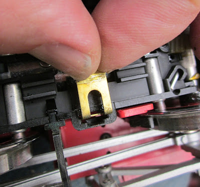
.... together with the two brass contact plates.
To remove the wheel contacts, I needed to ease the axles and wheels out of their housings ......
.... so the carbon brushes and their tubes could be pushed out with the blade of a screwdriver.
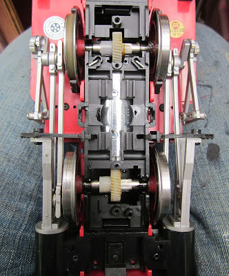
The wheels were then slotted back into place, making sure that the coupling rods and cranks were perfectly aligned on the leading and trailing wheels. I know from past experience that if the axles are even one tooth out on the worm wheels, then the loco will not run smoothly.
The baseplate was then screwed back into place, making sure it was the right way round (otherwise the holes for the smaller screws would not align correctly.
Stage 3 - Removing the motor block from the chassis
Having previously removed the four screws holding the motor block in place, I was now ready to ease the motor block out from the chassis moulding. However, before this could be done, the brackets holding the valve gear in place needed to be removed. The small screw securing each bracket to the running plate was removed - the screwdriver needing to be slotted between the coupling rods and connecting rods to access it.The brackets could then be eased out from behind the tanks ......
....... and 'parked' on the top of the motion.
The motor block was then carefully pulled away from the chassis.
The plug connecting the block to the loco body was then removed.
Stage 4 - Complete disassembly
The next task was to remove the chimney. Before this could be done the wires for the smoke unit needed to be disconnected from the contact pins on the circuit board.The large nut holding the chimney to the body was then unscrewed with pointed-nosed pliers - I could find nothing else which would fit into the confined space.
Once the nut had been loosened .....
.... the pipework holding on the cylinder covers was pulled out ....
.... and then the chimney was removed.
The front lamp was also removed, making sure that the bulb and wires were not snagged.
The four screws holding the cab in place were then removed.....
...... and the funnel-shaped pipe pulled out at the base.
This enabled the running plate to be removed from the cab and boiler assembly.
The driver's arm needed to be carefully eased out from the cab opening, to allow the running plate to be detached from the rest of the loco body.
The two weights in coal bins were then taken out as, if forgotten, they have a tendency to fall out when you are least expecting them to.
The two multi-pin plugs were then eased out from their sockets
I've discovered that, if the coal bins are pushed outwards, it's possible to lift out first one side of the boiler and then the other.
With this loco (unlike the other which I converted), there was an additional plug and socket which needed to be detached before the boiler could be fully removed.
The next task was to remove the cab roof. At first, I didn't think this would be necessary but I soon found out that it was very useful in helping to gain access to the wiring inside the cab. The four screws holding the roof to the cab were unscrewed .....
..... before the roof was then removed, revealing the soundcard and speaker.
II - Wiring up the loco
Now the loco had been split into its various components, I could start work on the new wiring for the battery and the radio receiver/motor controller. I spent a while trying to decide on the easiest way of connecting the receiver/controller to the existing system with the minimum of effort. In the end, I felt the easiest approach would be to connect through the lighting socket - as I had done when the loco was powered and controlled from the trail car (see How I converted a Stainz loco to battery radio control with a trail car). To gain access to the wiring for the lighting socket, I firstly had to remove the rear lamp.Stage 1 - Connecting the main supply
The lens was prised from the lamp body with the point of a craft knife.The white reflector was then taken out .....
.... to reveal the screw holding the lamp in place. This was unscrewed ......
........ which not only allowed the lamp to be detached .........
..... it also released the black plastic 'tools' moulding inside the cab. This enabled the rear glazing to be taken out (it needed to be slid upwards first which is why the roof was removed).
The circuit board for the rear light and the lighting socket was now accessible.
Two wires were soldered to the contacts on the back of the lighting socket. I could have soldered them directly to the circuit board but it was easier to use the contacts on the socket itself.
The grain of wheat bulb was removed from its socket ........
..... and a 3mm warm white LED was slotted in. At this stage I wasn't sure which way round it needed to go (as LEDs are polarity dependent) - I guessed the anode (+ve longer lead) would go into the left socket and the cathode (-ve) into the right socket and as it turned out I was correct.
The circuit board was put back into place and the glazing moulding slotted into place over it.
The lug on the 'tools' moulding was then inserted back into the hole in the glazing unit ........
...... and the lamp was screwed back into place.
Stage 2 - Replacing the resistors for the LEDs on the main circuit board
I next turned my attention to the main circuit board. This is located in the boiler. The baseplate of the boiler was removed by slipping the blade of a screwdriver behind the edge of boiler moulding.The baseplate was then removed .........
..... and the two screws holding the weight in place were unscrewed .........
....... to reveal the circuit board.
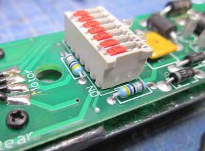
If your loco has a DCC decoder, it would need to be unplugged at this stage and all the red DIP switches turned to their ON positions. The three resistors for the LEDs were located, two beside the DIP switch block ........
....... and one near the front of the board. These were removed by pushing the point of a prodder underneath while a soldering iron was applied to one end ......
... until it came free.The other end of the resistor was then removed by the application of the soldering iron and some gentle pulling.
As I was going to be powering the loco with 12v batteries, 680ohm resistors were then soldered in place of the three original resistors. The value of the resistors required varies according to the voltage being used. If you are using a different voltage to power your loco then use an online LED resistor calculator such as http://ledcalc.com/
The grain of wheat bulb in the front lamp socket was removed and replaced with a 3mm warm white LED.
To ensure the LED was the right way round, leads from a 9v battery were connected to the diode (+ve lead) and resistor (-ve lead). I discovered my LED needed to be reversed in the socket ......
..... to enable it to be illuminated.
The plugs from the cab were inserted back into the circuit board to check that the rear LED was correctly connected. The leads from the battery were connected to the end of the diode (+ve) and a contact adjacent to the resistor.
Stage 3 - Installing the battery wiring loom
A miniature SPDT (on-off-on) switch was acquired .......... and three leads soldered to the contacts.
These were shrouded in heatshrink sleeving which was shrunk using the heat from the flame of a disposable lighter.
A pilot hole for for the switch was drilled in the cab floor just in front of the driver's feet.
This was enlarged with a 6.5mm dia drill ........
Two 1mm diameter holes were drilled in the rear of the raised section of the cab floor.
This was repeated on the opposite side and the holes then linked together to form a slot.
The wire from the centre contact on the switch was passed through these holes, together with a black wire. These would ultimately connect to the battery pack.
Another pilot hole was drilled into the cab floor to the rear of the driver's feet.
This was enlarged to 7.5mm diameter .......
.... and a 2.1mm DC socket was fixed into the hole. The wire from the foremost contact on the switch was soldered to the contact for the central pin of the socket. This was shrouded in heatshrink sleeving. The black wire was soldered to the middle contact of the three and another (grey) wire was soldered to the remaining contact (the output from the isolation switch).
Stage 4 - The interior light
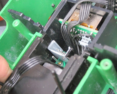
At this stage I decided to tackle the light inside the cab. As this light should shine whichever direction the loco was travelling I realised that I needed to make a diode bridge rectifier to ensure the direction of the current to the LED in the cab remains constant regardless of the supply. I could have used one of the outputs from the Deltang / RC Trains receiver / controller, but decided I might as well make the most of the loco's existing wiring. The contacts feeding the cab LED were de-soldered from the circuit board in the firebox ........... and a diode bridge was made from four diodes which I had to hand.
The two 'input' leads (ie the ones at the top and bottom in the above photo) were then soldered to the circuit board and the wires leading to the lamp socket were soldered to the other two leads. The grain of wheat bulb was removed from the socket and replaced with a 3mm warm white LED. (Note: After struggling to do this inside the confines of the cab as shown in this photo, I discovered the glazing assembly could be slid out, complete with the lamp socket, thus making replacement of the bulb really easy!).
Stage 5 - The battery pack
Three tagged 14500 (AA sized) 900mAh lithium ion batteries were acquired from Ecolux. There are many suppliers of batteries on eBay, and some of the claims made for the Amp Hour capacity of their batteries by some of them are, shall we say, optimistic. Ecolux guarantees the quality and the claims made for the batteries which are advertised on their website. Also, they will add solder tags to any of their unprotected batteries for no extra charge.I opted for the 14500s because they would fit unobtrusively on the cab floor. I decided to remove the raised mouldings on the floor to better accommodate the batteries.
This was done with a craft knife and a razor saw blade.
The solder tags on the batteries were snipped to a length of around 20mm and tinned with solder. A short length of wire was then soldered on to the +ve tag of one battery ......
and the other end of the lead was then soldered to the -ve tag of another battery.
This was repeated at the other end of the battery pack so that the three cells were interlinked in series.
If you are doing this for the first time then be extremely careful not to accidentally short circuit the battery leads. Lithium-ion batteries will rapidly overheat and start venting if short circuited. They could even burst into flames. You have been warned!!!
A 3S battery protection board was purchased from China through eBay. These boards will help to prevent the batteries from short circuit and also from over discharge. Lithium-ion cells are permanently damaged if their charge falls below 3 volts and can react badly if they are charged at too high a voltage.
Wires were soldered to the battery contacts (labelled B-, B1, B2 and B+).
These were then bent left and right alternately, and red and black leads were soldered to the main input/output contacts (P- and P+) on the board.
The board was then shrouded in heatshrink sleeving to avoid accidental short circuits.
The battery leads from the board were then soldered to the relevant tags on the batteries (ie B- to the unconnected -ve terminal. B+ to the unconnected +ve terminal, B1 to the other end of the battery connected to the B+ terminal and B2 to the other end of the battery connected to the B- terminal).
A 16v 2amp Polyswitch fuse was acquired .......
This was soldered to the negative output lead from the battery pack and to the black wire leading to the recharge socket. The positive lead from the battery pack was soldered to the red wire leading to the two way switch.
Two pieces of black plasticard were cut to the profile of the ends of the three batteries.
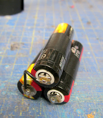
These were taped to the ends of the battery pack with insulation tape and the pack shrouded in tape. I didn't want to bind the pack too tightly to provide expansion space should the batteries ever need to vent.
Two 3mm diameter holes were drilled either side of the cab floor space ......
..... and a cable tie was inserted into one of the holes.
Another tie was linked to it under the floor and its end passed through the other 3mm hole.
The ties were then passed over the battery pack and linked together to hold it in place. On reflection, I could have drilled the holes further forward.
Stage 6 - Wiring up the receiver
A 2-pin 2.5mm JST-XH plug and socket set was acquired,The socket was connected to the plug ......
..... and wires were soldered to the contacts.
These leads were then shrouded in heatshrink and the other ends soldered to the motor output pads on a Deltang / RC Trains Rx65b receiver/controller
The leads from the plug were shortened and joined to the wires connected to the lighting socket.
The unattached red lead from the two way switch was then soldered to the +ve input pad on the receiver and the grey lead from the charge socket was soldered to the -ve input pad on the receiver.
The receiver was then shrouded in heatshrink and the receiver was attached to the back of the driver with another cable tie.
III - Testing
Before the loco was reassembled, the various plugs and sockets were linked back together. The receiver was switched on and when it entered bind mode, it was bound to one of my transmitters. The motor block was run forwards and in reverse to make sure the motor contacts had been wired up correctly and to check that the directional lighting operated as expected.I was delighted to discover that everything worked faultlessly the first time (it doesn't always work out like that!). The process of reassembly could now begin with confidence.
IV - Reassembly
The roof of the cab was attached first. The four screws holding it in place were screwed back into place.The circuit board was then attached to the boiler weight with its four screws .....
.... and the board and weight were screwed back into boiler with the two screws which hold it in place.
The small white plug linking the boiler to the can was inserted into its socket on the circuit board .....
.... and then the boiler was clipped back into place in the front of the cab.
The two multi-pin plugs were inserted into their sockets ......
.... before the base of the boiler was clicked back in place.
The plug linking the receiver to the lighting plug was inserted into its socket ......
...... and the weights were slotted back into the coal bins in front of the cab.
The cab was then attached to the running plate and screwed into place with its four screws.
The cylinder cover plate was then inserted into the underside of the front of the running plate .....
.... and the pipework re-inserted into the relevant holes on each side.
The chimney, together with the front lamp, was threaded back into its hole in the smokebox ......
...... and the nut tightened up underneath.
The leads for the smoke unit were left unconnected as the smoke unit draws a lot of current and I've never been one for creating smoke. The plug was inserted into the socket on the motor block and then the motor block was carefully eased back into place in the running plate / sub-chassis .......
.... making sure that the supports for the valve gear weren't trapped.
The valve gear supports were then screwed back into place with a single screw on each side.
The vent pipe in front of the cab was clipped back into place .......
...... and the ploughs screwed back on at the front and rear of the loco.
I had removed the cab steps and so these were also screwed back on.
And (almost) finally, the four screws holding the motor block to the rest of the loco were screwed in.
The final job was to re-attach the whistle to the cab roof.
V - Playing Test Running
The loco was then taken out into the garden for some testing ............ and as I now had two Stainz locos, I decided to run them as a double header.
While I was converting the second loco, I let the first loco run continuously around my main circuit with a train of two coaches and six wagons. She ran continuously (at about half speed) for two hours and forty minutes. Not bad for 900mAh 14500 lithium batteries which power her - and plenty of time for a running session in which I usually have three locos handling the trains in roughly equal measure.
The LGB Stainz loco is well engineered and crafted and has found its way into the hearts of many modellers starting out in garden railways. As you can see from the video, they are phenomenal haulers for their size and they are very controllable - with very precise slow running when used in conjunction with a good radio control system such as the Deltang / RC Trains Rx65. My original starter set Stainz has now joined the loco fleet of the Peckforton Light Railway and, although she is presently in her LGB livery, I'm sure it won't be long before the General Manager of the PLR insists that she pays a visit to the paint shops. Who knows, she might even get a complete makeover!
As for the other Stainz - she is now winging her way to the other side of the world where she will become one of the first locos to run on Peter Mack's new line - the Westbury, Osmaston and Quamby Railway.


















16 comments:
Thanks for such a detailed and informative instructional blog, it always amazes me that you have the patience and time to put such masterpieces together. It must have taken as long (or possibly longer) to produce this than carrying out the actual job. Truly inspirational and puts any of my work to shame.
Phil
Thank you so much for such a professional and detailed "how to". I have a couple of Stainz's, bought with a job lot of stuff for my Gn15 layout, Pallingham Quay. I baulked at setting up a track for them, as the price of a decent amount of track is way out of my price bracket! Plastic track is, however affordable, and there are no worries with track cleaning.
Thanks for your comments, Philip. I tend to write my blog entries while 'watching' TV in the evenings - half and eye on the TV and half an eye on my laptop. Let's face it, most things on TV these days only require half of one's attention. Once I've inserted the pictures into the blog, the text sort of writes itself. Never sure whether I've got the balance right between the amount of detail and over-daunting the reader, though. However, sometimes I find myself having to repeat or redo a job and I find it handy to read back over a blog posting. I did this with this job - re-reading my blog post about installing a decoder in my Stainz to check on the disassembly process which is a bit convoluted on the Stainz. The level of detail seemed about right for me, so presumably it will be about right for others as well for those wanting to repeat the process - though for the casual reader I assume it will be over-facing.
Thanks Peter. I hope it helps to give you sufficient knowledge to have a go. My next job is to bash the Stainz into something a bit more UK-looking. Fortunately, one of my mates in Oz has posted something on his website which will help - see http://www.trainweb.org/btr/Stainz.pdf http://www.trainweb.org/btr/Stainz.pdf. The internet can be so useful (sometimes!).
Thank you for this awesome "how to"! Your blog and your exceptionally detailed instructions are the inspiration for my garden railroading adventure. I purchased a LGB USA-spec starter set that included a Stainz 20212 locomotive. I then purchased your RCT-Rx65b receiver/controller and RCT-Tx24 Transmitter as well as other required parts so expertly described in your blog. Other than tinkering around with an Arduino and some basic experience with Z-scale and HO-scale model railroading, I don't have any real electronics background. Using your guide as a reference I was able to convert my 20212 Stainz to battery power with LED directional lighting! I'll admit that it was quite challenging at times, but your photos and instructions proved to be invaluable! I ran into a few obstacles (I must have an older, decoder-unfriendly 20212 Stainz with a very different circuit board than yours) but to my own amazement I was able to put it all back together and I had an operational, battery powered, radio controlled locomotive! I bought some additional track and finally setup a test loop in the garden today. Everything worked and my two sons were so excited to watch the little Stainz drive around the garden! Thanks Ge Rik! How cool!
Hi Zeke
I'm really glad my scribblings have come in useful and great to hear you got your Stainz loco batteryised and running. Thanks for the feedback - makes it all the more worthwhile.
Rik
Thank you so much. I'm looking to buy an LGB 2-4-0 tender locomotive, in hopes I can apply your most excellent instructions to it. It would seem to be a good candidate, having space for the equipment. May even try to Anglicise it.
Best wishes, Tom
Good luck, Tom. Would be interested to see how it turns out
Rik
Thank you. Have a second hand, unused Stainz on its way from Ebay. Cheaper than a 2-4-0 tender, so less to lose if I mess up. Have no knowledge of electronics, so will be following your blog very carefully. Have ordered a battery protection board from China, and looking to source the other components. Will anglicise it. Hopefully can alter the Germanic windows to round. Think that might help.
Best wishes, Tom
Sounds interesting. I hope it turns out ok. If you need any help just ask.
Rik
Hi Rik, Thank you. I'm all ready out of my depth. I see on Ecolux there are four types of 18650 batteries with different mAh. Would you be so good as to recommend the one I should buy? To have them tagged, can that be done on their website? Also exactly which charger to get.
I see on eBay there are different types of 680 ohm resistors and 16v 2 amp pole switch fuses. If there is a shop you would recommend, that would also help, that I might obtain the electronics. Can't find 3mm warm white LED's.
As you see, I know nothing. My email is; tomellis1947@hotmail.co.uk, if that is easier.
Thank you again. Tom
Tom
Email sent
Rik
Dear Rik,
I'm planning to convert my LGB Stainz loco to radio control, because I have the same track cleaning and track power probems as you. Unfortunately, i'm an absolute beginner in this topic. I've read your article how you converted your Stainz, but I have to admit there are a few things I do not understand perfectly...
Could you help me how to manage my "big" (at least for me) project? Can I contact you somehow (email etc.)?
Thank you!
Martin
Hi Martin. Only too happy to help but I'd rather not post my email address on here as it will attract loads of spam.
I suggest you join the gardenrails.org forum and then we can exchange messages and/or you can post a thread and get not only my views but also those of other forum members.
My name on the forum is the same as it is on here - is GE_Rik
Rik
Thank you Rik, I'll join the forum.
Martin
I look forward to welcoming you aboard.....
Rik
Post a Comment