Saturday, April 22, 2006

How Did I Lay the Track?

My experience of railway modelling is rooted firmly in 4mm scale 00 gauge. Hence, I am used to laying yard lengths of Peco flexible track. When I came to venturing into the garden, the thought of bonding together hundreds of short lengths of preformed track made me shudder so I investigated alternatives. The GRS (Garden Railway Specialists) website listed 1.5m lengths of rail and sleeper packs which seemed ideal. I preferred the larger (R3) radius points/turnouts for the main circuit and so opted for Tenmille. Only later did I find that their points were no longer being manufactured.

Tenmille track has a slightly narrower profile than LGB track and needs special rail joiner to link with LGB track. However, it looks good and is easy to lay.

Update 28/8/09

I've since combined LGB, Tenmille and Aristo track in several places (eg See Peckforton Station comes to life) and have found that LGB rail joiners/fishplates are fine for linking together all forms of trackwork - no need for the special Tenmille rail joiners which are a bit of a fiddle to use anyway!
Another Christmas loomed and so this time I discovered 8' lengths of rail and sleeper packs made by Aristocraft could be purchased from OnTracks. I duly purchased a dozen lengths of their product. It arrived by special delivery in an 8' long aluminium tube - for which I'm sure one day I will find a suitable use!

Aristocraft track has more or less the same profile as LGB track though the brass rail is paler in colour. It seems softer than the Tenmille track and hence is easier to bend - though this is a mixed blessing as sometimes it bends too easily and can lead to kinking if you're not too careful. As you can imagine, it's almost impossible to unkink a kinked rail!  (eg see Rectifying poorly laid track - Progress Report 15)
Just recently, I have discovered that LGB sell 3m lengths of rail and sleeper packs. These I have ordered and will collect from Bay Models in Carnforth - though I'm not at all certain how they will fit into the car! I will keep you posted as to how this track compares with the others. (See - Peckforton Station comes to Life)

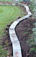
The trackbed comprises standard 4" breeze / hollow concrete blocks laid on their side. I had considered digging shallow trenches, shuttering and filling with concrete, but after laying the retaining walls for the raised beds I had a few breeze blocks left over and they seemed to do the job remarkably well. In addition they can be easily lifted and re-sited should I ever decide to redesign the layout. I have already done this when I decided to extend the stream. The gaps between the blocks are in-filled with cement. I tend to do this by hand (clad in rubber gloves) so the goo can be rammed in with fingers and smoothed off. I am hoping this will deter weeds from growing up between the cracks. I have also used a dry-mix method, brushed into the cracks. I'm not too sure about this method as the mix tends to infiltrate the flower-beds and I'm not too sure what it will do the the Ph of the soil!
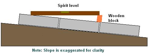
A builder's spirit level was used to ensure each block is level with its neighbour. The gradients were kept uniform by inserting a small block of wood under the lower end of the spirit level. 'Fine tuning' of the position of each block was achieved either by using sifted soil or, when it was available, builders' sand.
I am a little concerned about the durability of the breeze blocks. I appreciate that in time they will crumble as they are attcked by the elements. I am hoping that once the track has been ballasted with chippings held in place, either with a dry cement mix or diluted outdoor PVA adhesive, this will provide a protective surface layer. I'm not too worried if the exposed outer edges weather away - should look more natural.
The track is screwed to the blocks with rawlplugs. I have used either brass or zinc-plated screws - again with the intention of being able to remove the track is necessary.

Rectifying sunken blocks

 Despite my best efforts to firm up the ground underlying the blocks some have become more embedded than others, which has led to some undulations in the trackbed. I considered lifting the track and re-bedding the blocks but I wondered whether this would create more problems than it solved so I opted for a less radical solution - by levelling the track and then infilling with wet concrete between the track and the trackbed - for more information see Progress Report 24.

Wednesday, April 19, 2006

Progress report 2 - Track laying 2


A couple of half days without rain have enabled me to install some wiring and to lay a little more track. Nearly half the track is now down and a test train has been run successfully.


To fix the track in place, holes were drilled in the concrete 'breeze' blocks and rawlplugs inserted. Brass or zinc plated screws have been used to secure the track. This gives me the option to remove or re-site track if the need arises. Ultimately, the track will be ballasted - but not until it has been thoroughly tested.

The stream needs to be cleared of dead leaves as does the 'sump' into which it flows (see How I constructed the stream). For now, track-laying takes precedence.

As can be seen, I laid the cross-over which will form the link for the reverse loop. The wiring for the loop has been installed. As I will want trains to run in both directions around the loop, trains to be reversed will have to stop at the through station (as yet unnamed) while the polarity of the loop is reversed.

The track for the through station has yet to be laid, but the track-bed is in place. The wiring will be buried, once it has been soldered to the track and tested.


The terminus (again unnamed as yet) is nearly complete. The sidings need to be added - but for now I have run out of track. A trip to Bay Models (Carnforth) is scheduled for next weekend. My wife is researching her family history and is keen to visit Grange-over-Sands to see if the house in which one of her ancestors lived is still standing. Not sure yet how I will manage to fit twenty 3m lengths of rail in the car - let's hope the weather will be warm enough for the sun roof to be open!!

The link between the terminus station and the the storage area has now also been completed, together with the combined train/cat flap - a hinge needs to be added to the top of the train-flap, however! The cat-flap mechanism has been butchered from a redundant cat-flap and has been duly inspected and tested by the animal in question. This is the prototype - I will probably make a more elegant version when time permits!

While the rain fell, I completed the baseboard for storage tracks in the lean-to. I'm on more familiar ground here - 2"x1" framing with 1/2" chipboard. All I need now are some tracks - and a few more locos - and more stock.............

----oo0oo----

How Did I Bridge the Gaps?

Whenever I read articles about others' railways, I am always interested in finding out how they solved various problems in the construction of their model. I do not profess to be an expert, but you may want to share in my experiences.

Bridging the gaps
The design of my railway required two gaps to be bridged. One, relatively insignificant (approx. 4') to provide access to what will be a small patio and another more substantial (approx 12') to provide access to the shed and the shelter housing the trailer tent.

My initial thoughts were to provide a lifting bridge for the short span - one which would fold back on itself. This would have required hinges which stood proud of the tracks.


However, this would have increased the width of the bridge and detracted from its appearance. Browsing through the local DIY store, I came across a couple of hefty brass hinges which looked promising. The sort of thing from which you could hang a heavy door - or even a substantial bridge!


So here's the solution. Yes, I know they don't look too elegant at the moment - but the do the job and, when time permits, I intend to add some sort of bridge-like superstructure. I'm torn between constructing a sub-structure to make the bridges resemble viaducts (maybe too heavy) and investing in some aluminium extrusions and making girder bridges. With the long bridge I may do a combination of both. The centre-post for the long bridge is removable, by the way.

The wood for the bridges and their supports has been 'recycled' from an old fence which was erected over 20 years ago. It reeks of creosote and is still remarkably well preserved. I'm hoping it will last at least another 20 years!!


Update (3/5/08)
It is now two years since this part of the line was completed. The bridges have fared well, the construction technique seems to be appropriate, though the long bridge above is beginning to sag in the middle and the end nearest the camera is starting to deteriorate, presumably because air cannot circulate and it remains damp for prolonged periods.
In addition, the hinged end has dropped slightly (a couple of mm), so needs propping-up to provide a smooth transition across the gap.
Update (26/8/09)
I've now 'prettified' the longer swing bridge using uPVC trim - a very inexpensive and easy way to make effective girder bridges.


For more information, see 'How I made the swing bridge'.
What have I learned?
In future, I will place roofing felt beneath the track to act as protection for the timbers beneath. I will also use felt as the bed for the end of the long bridge as this might reduce the amount of dampness between the bridge and its support.
Update (26/8/09)
No sign of rot in the unprotected timbers as yet. However, for the timber-based extension, I used roofing felt (see How Did I Build the Extension?). It's too early to make a comparison of the two methods.

Tuesday, April 18, 2006

Progress Report 1 - Laying the track

Track laying is now under way


Easter 2006 and, with a break in the wet weather, the first of the track has been laid.

As can be seen, some of the planting has begun to be established and a water-feature in the form of a small stream has been installed. This will be extended as time permits.

The track-bed has been completed (I ran out of funds last year) and swing-bridges have been constructed for the two access-points.

At present, it is raining yet again and hence track-laying is suspended. However, it is hoped that the first trains will be running by the middle of May 2006!

Watch this space!

<< Go to Getting Started 

Rik's Railway

The genesis of a garden railway


This Blog describes the ongoing development of a G scale garden railway which has so far taken around five years to plan and prepare for the coming of the railway.

I have always wanted to build a garden railway since I first became interested in railway modelling (c1960). My dad was not best pleased when the Triang train set he bought for me ended up rusting in the garden! (see Railway Modelling and Me)

When eventually I had the funds and some stability, I started by buying an LGB starter set (two four wheeled coaches, a 0-4-0 Stainz loco and a circle of track). Four years later, a file full of tentative plans, several books, magazines and visits to numerous websites later, a plan was drawn up. (see Where did I get my ideas from? and Planning the Railway)

We have an awkward L-shaped garden bordering a belt of trees and facing north. Several designs for the completed layout had been considered but eventually a looped figure-of-eight was chosen as it seemed to make the most of the available space.

After living for around twenty years with a very uninteresting design of garden the decision was made to re-model. Over the years, saplings had grown into large, awkwardly placed trees. These were 'removed' by a qualified tree surgeon - a tree fella!

Next came marking-out of the intended track-bed and flower-beds. This was done with a series of posts at around one metre intervals positioned using a spirit level to get some idea as to which soil needed to be moved from where to where.

Before the landscaping of the garden could be started, a lean-to was constructed on the back of the house. This was intended to act as both a wellie store and also a safe haven for the trains when not in use. (see How I made some stock boxes)

After searching the pages of the local free ads paper some second-hand double-glazed windows were purchased; these dictated the size and shape of the lean-to. A few websites were visited to find out how to lay bricks. In the end I 'cheated' by buying a 'Bricky Tool' - a simple gadget which helped ensure the bricks were laid neatly.

Construction of the lean-to was completed during the "Summer" of 2004 - which was one of the wettest in the North West of England since records began.

Maybe not the most elegant of structures - but it is functional! If you click on the photo of the lean-to you will see the 'portal' for the railway on the left of the front wall. A cat-flap was installed in this for times when it was not being used by the railway.


With the lean-to completed work could at last start on the landscaping.

In place of two clapped-out sheds and trailer-tent store, a new shed was constructed together with a new shelter for the trailer-tent.

Then, around three tonnes of soil was dug out and wheel-barrowed from one end of the garden to the other. My researches had shown that garden railways are better if they are mounted above ground level. The reasoning is that it involves less stooping (something worth considering as I totter into old age), the trains are easier to see, and maintenance is a lot less arduous. So, using the purpose-built 'train'flap' into the lean-to as the datum (see above - at the left-most end), the flower-beds were built up and the lawn area was lowered.

The edges to the raised beds were made using breeze-blocks. A foundation trench about a foot deep was dug and half-filled with rubble, stones, gravel, broken bricks and all sorts of detritus which was dug up from the garden. It seems that when the house was built twenty odd years ago, the garden was a dumping ground for all sorts of builders' rubbish - over 50 usable bricks were rescued in this way. The breeze-block walls were clad with chunks local sandstone which can be cleaved into thin slabs using a cold chisel and hammer. To help the sandstone adhere to the blocks, generous amounts of PVA were added to the mortar mix. (see How I constructed the raised beds)

[Update June 2009: So far only two pieces of sandstone have fallen off - I think this was because the concrete mix was allowed to dry out too much - I did it on a sunny day - we do have them in this part of the country!]

Once the raise beds had been constructed the trackbed was laid. Two 3' x 2' paving slabs mounted on brick based were used as the foundation for the main terminus station. It is certainly solid and secure (with storage beneath) but quickly blunts masonry drills! I decided to use breeze blocks for the trackbed. First, I had around a dozen left over after building the lean-to and the raised beds, secondly, they are easy to position and, if ever I change my plans, re-position. Thirdly, they are about the right width and lastly, they are easy to drill into for taking rawlplugs to fix the track. I had decided to use Tenmille and LGB flexible track which, unlike pre-formed track, needs to be fixed down securely as, once curved, it likes to try straightening itself out again. Hence, the track-bed needed to be solid. (see How I laid the track)

By Autumn 2005, most of the landscaping had been done and the first foundations for the track were in place (see picture).

Go to Progress Report 1 >>