Five methods have been used over the years to fix the ballast in place:
1. Using cement
2. Using PVA adhesive
3. A combination of the above two methods
4. Using tile adhesive
5. Wet mix plus dry dressing for station areas
Each approach has its merits and, it seems to me, that the choice of method is largely dependent on cost, purpose and desired outcome.
The ballast I have used for my 45mm gauge mainline trackwork was 2mm alpine pink gravel, which I found in my local garden centre in 'handy packs'. Each pack is sufficient for around 12 - 18m of track dependent on the method used.

In station areas, I have used a wet mix of cement together with a dry-mix top-dressing of sifted soil, sand, crushed coal and bird grit.
For the 32mm copper mine feeder, I have used bird grit into which was mixed crushed pottery shards. My reasoning being that the miners will have used the freely available sandstone spoil from their mining as ballast.
1. Using cement
I have found this method the simplest to apply. The bag of gravel was mixed with builders' sand in the proportion 2:1 (ie a bag of gravel to half a bag of sand). To this was added the equivalent of half a bag of cement. In other words gravel:sand:cement = 2:1:1. I wanted a fairly strong mix to ensure the gravel would be held in place.
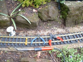
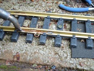
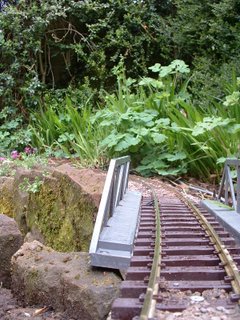
Once the ingredients had been thoroughly mixed, it was trowelled on to the track:

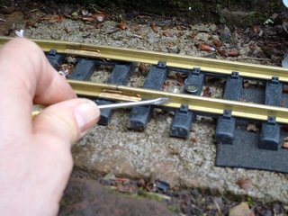
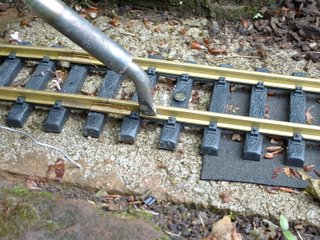
The ballast was then carefully brushed into place with an old paintbrush:
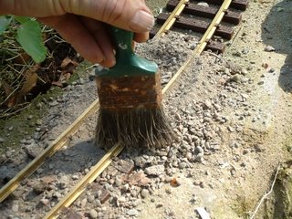
Care was taken to ensure there was not a build-up of ballast on the inside of the rail and also that it was kept well away from point mechanisms.
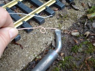
Once the ballast was in place, it was given a gentle dowsing from a watering-can fitted with a very fine rose. It's important not to wash the ballast out from where it has been carefully brushed or to dowse it so much the cement powder is sluiced away. I could have let nature take its course if light rain was forecast, but a downpour would have been disastrous before the cement was set.
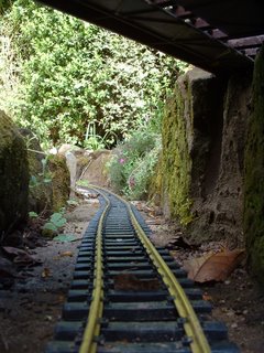
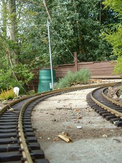
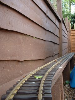
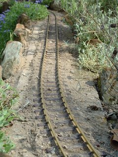
The resulting ballast give the appearance of narrow gauge track which has been ballasted cheaply with grit rather than gravel.
The cement method is fairly easy to do. It's not particularly time-consuming once the ingredients have been mixed and is not too expensive. A bag of cement is relatively inexpensive compared with PVA and the addition of a portion of sand makes the ballast stretch further. However, the end-result is less attractive than the pure PVA method (see below) and resembles ballasting seen on poorly maintained narrow-gauge railways. I have found it easy to lift the track with this method, the ballast crumbles away.
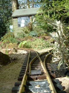
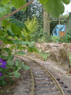
Update four years on
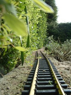
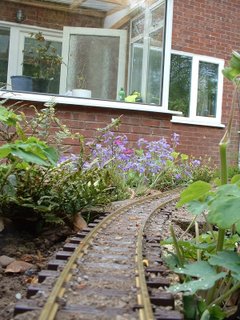
I thought you might be interested in how this approach has weathered over the past four years:
As you can see, the ballast is probably in place (hard to tell) and a healthy growth of moss has covered it all. Personally, I'm more than happy with the moss as it gives the track a slightly neglected look, which is fine for the type of railway I'm modelling (a struggling British light railway in the early 1930s). Those wishing to model something more affluent (eg a Swiss railway) may prefer something less verdant.
2. Using PVA
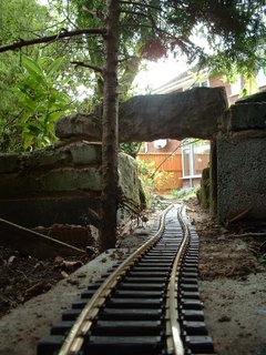
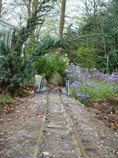
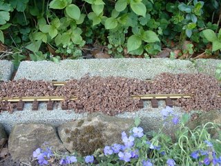
The PVA approach gives a result which resembles carefully ballasted and well maintained track:
The gravel is used 'neat' from the bag and, as with the method above, is trowelled and brushed carefully into place:
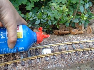
Once the ballast in in position, it is dowsed in water from a watering-can fitted with a fine rose - being careful not to sluice away the gravel. The gravel is then flooded with diluted exterior / weatherproof PVA adhesive, to which a small quantity of washing-up liquid has been added to encourage it to flow into the gravel.
The PVA method takes longer and is more expensive. The PVA adhesive is not cheap and even though it is diluted, does not stretch far. However, the result (in the short term - see below) is more attractive as it resembles carefully maintained, well-ballasted track. Once set, the ballast becomes a fairly solid mass and hence I will imagine it will be more difficult to lift the track. I have read elsewhere that attempting to use interior PVA, although less expensive, is not a wise move as it very soon deteriorates outdoors.
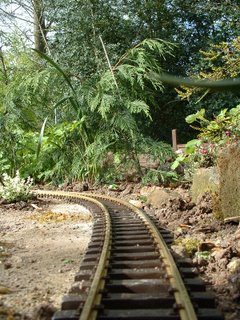
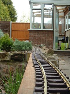
Update four years on
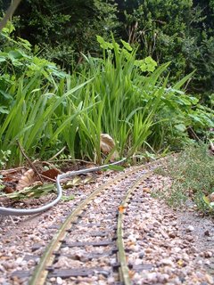
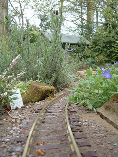
Again, how has this method fared?
As can be seen, there's some, but not a great deal, of the ballast left in place. Whether the frost has broken it up, or birds has dislodged it, I can't be sure. But considering the additional effort which needs to be put into this approach I'm not convinced the longer-term return makes it worthwhile.
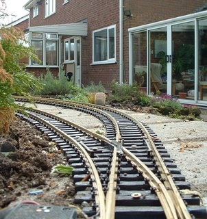
3. The combined PVA/Cement method
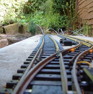
When I extended the line (see
How I built the extension), I mounted the track on wooden supports covered in roofing felt. To ballast this track I used the cement method as above but rather than watering it in, I dribbled watered-down PVA over the whole thing and then watered it in. The whole lot dries rock-hard and does not seem to want to go anywhere. This has now become my default method of ballasting.
Although this track has not been in place as long as the rest of the railway, after a year and a hard winter, the ballast seems to be holding-up well. When I needed to lift some of this track to add some more sidings (see
Progress Report 28), the ballast crumbled away readily, though was a little more persistent in clinging on to the sleepers than the cement-only method.
In four years' time, I will post another update on how well this approach is doing.
Postscript
In a couple of places I have used wet-mixed concrete to in-fill where some of the blocks had sunk (see
Progress Report 24). After a year, moss is beginning to attach itself to this ballast so I anticipate that eventually it will be indistinguishable from the surrounding track.
4. Using Tile Adhesive (method developed in 2014)
After six years, I've discovered that the above methods work for a while but eventually the bond between the materials breaks down. In some places the ballast was fixed
down well whilst in others it had been washed away by the elements.
After
relaying some ceramic floor tiles in the kitchen I had half a bag of
tile cement remaining. I'd found the previous tile cement had been very
effective, adhering to the old tiles extremely well. I figured it was
the mix of fine sand and adhesive in the tile cement that provided a far
more effective bond. If it works for tiles, why not for trackwork? I'd also noticed there was a whiff of PVA adhesive (or similar) emanating from the tile cement - so maybe it includes an additive to aid adhesion.
As with my previous approaches, I dry-mixed the tile cement in equal measures with potting grit.
This was then trowelled on to the track ......
..... and brushed into place with a 1" paintbrush.
The
ballast was then watered with a watering-can to which a few drops of
washing-up liquid had been added to help break down surface tension.
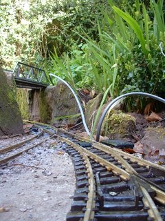
In addition to the newly relaid section of track, the adjacent track .........
...... and other sections where the ballast had been washed away...........
..... were also re-ballasted.
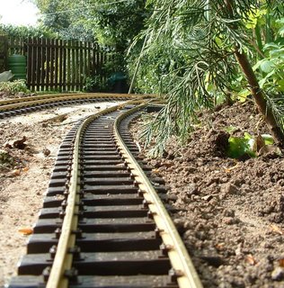
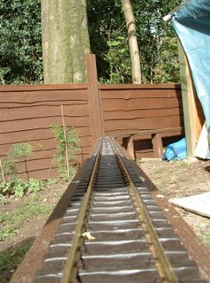
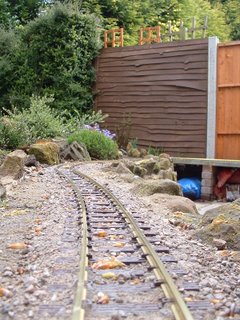
A few more shots, now the tile cement has had a chance to harden off (around two weeks after the ballast was applied) ......
 |
| The track beside the stream just outside Peckforton Station towards Bulkeley. |
 |
| The approach to Peckforton from Beeston Castle |
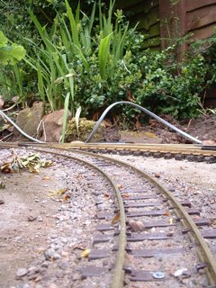
 |
| The cross-over between Bulkeley and Bickerton (looking towards Bulkeley) |
 |
| The approach to Beeston Market |
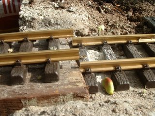
 |
| A close-up of the approach to Beeston Market |
Time will tell whether this approach is
more enduring than my previous
attempts, but early signs are that it has a tougher
finish which will hopefully protect it from the worst of the weather.
The true test will probably be the extent to which it survives the frost
in the winter months.
5. Wet mix and dry dressing (for station areas)
The disadvantage of using the above methods in station areas is that there always seems to be some loose ballast which clogs up the pointwork. So I decided to use a wet-mix approach for station areas. However, because this did not look realistic when it dried, I then gave it a surface dressing of dry-mix fixed in place the SBR adhesive (a waterproof PVA cement additive).
The wet mix is used to infill between the tracks and provide a foundation for the top dressing.
The top dressing is a dry-mix of sifted soil, sand and crushed coal with bird grit (largely crushed sea shells) for the ballast in and around the tracks.
Once the dry-mix has been brushed into place, it is wetted and diluted SBR adhesive is dribbled on.
To tone down the contrast between the patches of different coloured dry-mix, it was then given a wash of highly diluted black cement dye. In muckier areas (eg where locos take on coal and water), the dye was diluted less to provide a stronger colouration,
This seems to provide a good representation of the sort of ballasting which would be found in station yards.
For more information see
How I ballasted Beeston Market station yard.