I take no credit for inventing this device, there are plenty of examples already in existence but, after having had a few derailments from small twigs and leaves falling on to the track, I decided it was time I had made myself something which could keep the tracks clear.
The most important item was to track down a bottle brush which was not too long and which had two plain ends (some had rounded ends which were not suitable). I bought mine from my local DIY store for £2.99. I did previously buy a slightly longer one from a supermarket but when I tried cutting the brush shorter, the bristles fell out.

I cut off the handle (using a junior hacksaw), leaving around 1.5cm of stem for the axle and pulley. Wire was removed from the other end and the bristles fluffed out.

10mm and 15mm lengths of 7/32 brass tube were cut and fitted to the ends of the brush, with a dab of superglue to hold them in place.

Superglue was also used to secure the bristles in place along the brush. I'm not sure if this is absolutely necessary but decided it might be worthwhile, given the harsh treatment they are likely to receive. I found it was advisable to be sparing with the glue, otherwise it will stick the bristles to each other.

Next, I sorted out the components for the chassis of an HLW mini series wagon. I have a few of these sitting on the shelf ready to be dusted off for wagon projects (eg see How I made some open wagons - How I made a crane wagon - How I made some flat wagons)

The solebars were slotted into the base of the wagon ........

...... and then one coupling was screwed into place and a couple of sets of Bachmann metal wheels were slotted in. I prefer to use metal wheels as they give the wagon extra weight and also enhance its smooth running.

Making the chassis provided an opportunity to measure whereabouts the brush needed to be mounted so it would brush the tops of the sleepers.

Two 20cm lengths of Code 322 rail were cut and then a vee was filed 5cm from the end of each. Another vee was filed on the opposite side of the rail 2cm from the first vee.

Both rails were then bent to form z-shaped beams on which the brush would be suspended. The bends were reinforced with fillets of solder. Two brass brackets (12mm x 35mm) were then soldered to the ends of the beams with 6mm holes to act as bearings for the brush.

Two 12mm x 85mm plates were then cut from brass strip and 2.5mm holes drilled 25mm from each end.

These were then tinned with solder at each end.........

........ before being soldered to the beams. Holes were then drilled in the base of the wagon chassis to enable the assembly to be bolted on.

A 12v motor was mounted in a 25mm wide brass U-bracket .......
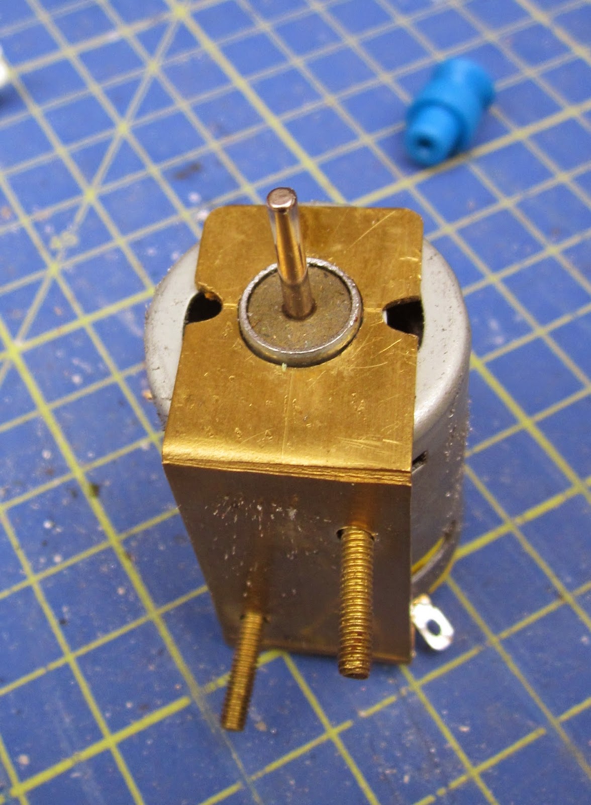
..... into which holes had been drilled to enable the motor to be mounted on the wagon.

I had insufficient 25mm wide brass strip and so a 113mm length of 12mm brass strip was cut, to which a 25mm wide plate was soldered, with holes to take the motor bracket (NB These holes were later slotted to enable the position of the motor to be adjusted to allow the pulleys to be lined-up).

The bracket was then soldered to the beam above the brush and the motor bracket bolted on to it.

A 40mm piece of 12mm brass strip was then soldered on to the side of one beam with a hole drilled in to take a switch.

The assembly was then bolted on to the wagon chassis and the motor wired-up through the switch to a 9.6 volt NiMh rechargeable battery pack. A pulley was pushed on to the end of the motor shaft and another on to the end of the brush. I found I needed to file the holes in the brass strip beneath the motor bracket into slots to so the pulley on the motor could be aligned with the pulley on the brush (otherwise the belt keeps slipping off).

To finely adjust the height of the brush above the track, I eased the bolts at the front of the assembly and inserted a couple of wooden strips (from lolly-sticks) until the brush was just clearing the sleepers (too high and it misses smaller leaves and twigs, too low and there is too much friction on the brush). You can just see these wooden wedges below the motor in the picture above.

I've found that the brush is a little too wide which means that on some stretches of track the pulley becomes entangled in the undergrowth. This can, of course, be trimmed back. Fortunately, the brush is narrow enough to fit between the abutments of the overbridges - just!.

I could have put the pulley-wheel inside the frame, but this would have meant the frame would have had to be dismantled each time an elastic band snapped - which does seem to happen quite regularly - I must find a decent source of stronger pulley belts of the correct size!
In the meantime, she may not be the prettiest vehicle to have emerged from the workshops - but she is functional and will save my back when getting the railway ready for running.
Approximate costs (though everything apart from the brush I had to hand in the workshop)

The most important item was to track down a bottle brush which was not too long and which had two plain ends (some had rounded ends which were not suitable). I bought mine from my local DIY store for £2.99. I did previously buy a slightly longer one from a supermarket but when I tried cutting the brush shorter, the bristles fell out.
I cut off the handle (using a junior hacksaw), leaving around 1.5cm of stem for the axle and pulley. Wire was removed from the other end and the bristles fluffed out.
10mm and 15mm lengths of 7/32 brass tube were cut and fitted to the ends of the brush, with a dab of superglue to hold them in place.
Superglue was also used to secure the bristles in place along the brush. I'm not sure if this is absolutely necessary but decided it might be worthwhile, given the harsh treatment they are likely to receive. I found it was advisable to be sparing with the glue, otherwise it will stick the bristles to each other.
Next, I sorted out the components for the chassis of an HLW mini series wagon. I have a few of these sitting on the shelf ready to be dusted off for wagon projects (eg see How I made some open wagons - How I made a crane wagon - How I made some flat wagons)
The solebars were slotted into the base of the wagon ........
...... and then one coupling was screwed into place and a couple of sets of Bachmann metal wheels were slotted in. I prefer to use metal wheels as they give the wagon extra weight and also enhance its smooth running.
Making the chassis provided an opportunity to measure whereabouts the brush needed to be mounted so it would brush the tops of the sleepers.
Two 20cm lengths of Code 322 rail were cut and then a vee was filed 5cm from the end of each. Another vee was filed on the opposite side of the rail 2cm from the first vee.
Both rails were then bent to form z-shaped beams on which the brush would be suspended. The bends were reinforced with fillets of solder. Two brass brackets (12mm x 35mm) were then soldered to the ends of the beams with 6mm holes to act as bearings for the brush.
Two 12mm x 85mm plates were then cut from brass strip and 2.5mm holes drilled 25mm from each end.
These were then tinned with solder at each end.........
........ before being soldered to the beams. Holes were then drilled in the base of the wagon chassis to enable the assembly to be bolted on.
A 12v motor was mounted in a 25mm wide brass U-bracket .......
..... into which holes had been drilled to enable the motor to be mounted on the wagon.
I had insufficient 25mm wide brass strip and so a 113mm length of 12mm brass strip was cut, to which a 25mm wide plate was soldered, with holes to take the motor bracket (NB These holes were later slotted to enable the position of the motor to be adjusted to allow the pulleys to be lined-up).
The bracket was then soldered to the beam above the brush and the motor bracket bolted on to it.
A 40mm piece of 12mm brass strip was then soldered on to the side of one beam with a hole drilled in to take a switch.
The assembly was then bolted on to the wagon chassis and the motor wired-up through the switch to a 9.6 volt NiMh rechargeable battery pack. A pulley was pushed on to the end of the motor shaft and another on to the end of the brush. I found I needed to file the holes in the brass strip beneath the motor bracket into slots to so the pulley on the motor could be aligned with the pulley on the brush (otherwise the belt keeps slipping off).
To finely adjust the height of the brush above the track, I eased the bolts at the front of the assembly and inserted a couple of wooden strips (from lolly-sticks) until the brush was just clearing the sleepers (too high and it misses smaller leaves and twigs, too low and there is too much friction on the brush). You can just see these wooden wedges below the motor in the picture above.
I've found that the brush is a little too wide which means that on some stretches of track the pulley becomes entangled in the undergrowth. This can, of course, be trimmed back. Fortunately, the brush is narrow enough to fit between the abutments of the overbridges - just!.
I could have put the pulley-wheel inside the frame, but this would have meant the frame would have had to be dismantled each time an elastic band snapped - which does seem to happen quite regularly - I must find a decent source of stronger pulley belts of the correct size!
In the meantime, she may not be the prettiest vehicle to have emerged from the workshops - but she is functional and will save my back when getting the railway ready for running.
Approximate costs (though everything apart from the brush I had to hand in the workshop)
| HLW wagon chassis | £ 12-00 |
| 12v motor | £ 5-00 |
| Battery pack | £ 5-00 |
| Brass rail and sheet | £ 5-00 |
| Bottle brush | £ 3-00 |
| Pulleys | £ 1-50 |
| Bachmann wheels | £ 7-50 |
| Solder/wire etc | £ 1-00 |
| Total | £40-00 |


