Friday, March 06, 2015

Progress Report 57

Normally, I don't post that many Progress Reports in the winter months, but a few things have happened since my last report in January which are worth recording.

Leek & Manifold coaches

I am pleased to report that the Leek & Manifold (ish) coaches which I bashed from Bachmann Jackson Sharp (ish) coaches are now completed - well externally.

I still have to complete the interiors and add lighting. I'll probably add some cosmetic chopper couplings as well.

They took longer to convert than I had expected, but that was mainly because I decided to add a few more details than were absolutely necessary. I've described the conversion in another posting - see How I converted Bachmann Jackson Sharp coaches into Leek & Manifold coaches.

I tried to ensure that the running gear was not touched in any way as I knew these coaches would cope happily with the tight curves of my railway, however, I did extend the balconies by 10mm at each end. It was fortunate that I did not extend them further (to more closely match the capacious L&M originals) as on a couple of curves, the corners of the roofs touch each other. Had they been even a few millimetres longer they may well have levered each other off the track. You can just about see how close the coach roofs are in the fourth shot on this video of their test run.


New loco (and new gauge)

I don't always manage to find bargains on eBay, but a couple of weeks ago, I stumbled across a nice little 32mm gauge IP Engineering diesel loco which was going for a very reasonable Buy It Now price.

It was powered by two AA Alkaline batteries and control was manual, through a reversing switch (no speed control).

I decided to upgrade it by using a 18650 rechargeable li-ion battery and adding radio control, using a Deltang Rx65b receiver/controller (see How I converted a battery diesel loco to radio control).

I also exploited one of the Rx65b's addition features, by re-programming the receiver to operate in auto-shuttle mode (see How I re-programmed a Deltang Rx65b for auto-shuttle mode).

 I intend to use this loco to run a short train of skips from the copper mine to the loading hoppers and being able to leave it working in shuttle mode while I concentrate on operating the main railway. It will also be useful to have some 32mm gauge rolling stock to take on visits to fellow modellers' railways.

 She will be re-painted and have more detailing added, numbered 11 and named Linda. The li-ion battery will be disguised as a fuel tank.

Loco repairs and upgrades

As with the real thing, my model locos usually require some TLC to keep them in operating condition and over the winter period I tend to do general maintenance and servicing. I am intending to convert my remaining three track-powered locos to battery power.

The main reason these have not been converted so far has been the availability of space for batteries. I do not like the idea of using a trail car for batteries as I often run trains end-to-end and, unless I provide them with tenders, I would not want to trail a wagon when running round the train. I am also taking the opportunity to replace some of the early Deltang receiver/controllers with the most recent Rx65b which has a higher power rating than its predecessors.

I am presently constructing a 32mm gauge Simplex loco kit (see Progress Report 56). I am hoping this can also be made to operate under radio control and in auto-shuttle mode as with Linda, above. This loco will be numbered 12 and named Emma.

Stock storage

Owing to a chronic medical problem, I have had to abandon use of stock boxes to transport and store my rolling stock - instead, I have created storage tracks in the garage and have extended the baseboard at Beeston Market (see How I made some storage roads in the garage)


At the start of each operating session, I will now run the rolling stock out to position wagons in their previous locations. I have created some namecards to act as dividers showing the origins of each rake.


Peckforton Mine Tramway (PMT)

As indicated above, I have decided to create a 32mm (2') gauge railway to act as a feeder for the main 3' gauge railway. I have already acquired and modified one loco and am in the process of constructing a second (see above.

The cosmetic Gn15 railway which previously served the loading hoppers

is being replaced  with 32mm gauge track which will run a short distance beside the main line between the coper mine and Beeston Market Station. Work has started on making the embankment and bridges needed to take the railway to the loading hoppers.

Winter running

During the winter, I don't usually run full operating sessions, preferring to make the most of breaks in the weather to run the odd train now and again. I did, however, make the most of a light snow shower to run a couple of trains in the snow.

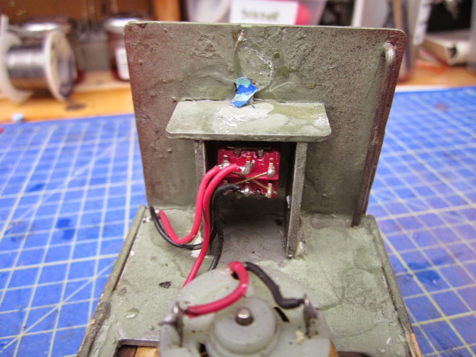
I was also interested in finding out the haulage capabilities of another of my battery converted locos (Barclay 2-4-0 loco No.2 Beeston).

This winter has been very mild in comparison with previous winters, and I have been able to keep the trains running more frequently. I must admit that converting to battery power has been one of the main reasons for encouraging me to grab opportunities to run trains with the minimum of preparation.


Monday, March 02, 2015

How I programmed a Deltang receiver for auto-shuttle mode with a Deltang Prog4

I have been using Deltang radio control equipment for my 16mm scale, 45mm gauge garden railway for around two years now and in that time the range of features on the receivers has grown steadily.

Initially, the combined receiver/controllers were not specifically designed for larger scale locomotives and so were limited to smaller locos which drew no more than 1 amp. Since then, the receivers have evolved into the most recent - the Rx65b - which is a combined receiver (rx) and Electronic Speed Controller (ESC) which can handle up to 3 amps at 18 volts.

In addition to improving their power handling capabilities, various other developments have been incorporated. The Rx65b now has up to 12 output ports and three additional ports which are buffered to handle up to 2 amps. As with previous receivers, the Rx65b can be programmed by the user to tailor the outputs (and inputs) to meet specific requirements. For example, the user can set the maximum speed at which a locomotive will run, can program light displays (eg a flashing sequence of lights for a modern diesel loco) and configure outputs to control servos (eg for remote uncoupling). In addition, the receiver has three auto modes - Buffer-stop (on reading the end of the line loco coasts to a halt and will not move until you change the speed or direction setting on the transmitter) - Station-stop (the loco coasts to a halt at a station, waits, and then departs in the same direction) - and Auto-shuttle (at the end of the line the loco coasts to a halt, waits, and then departs in the opposite direction). The time taken to slow down and the wait time can be programmed by the user either using a conventional DSM2 aero transmitter, an RC Trains / Deltang Tx20 or with the Deltang Prog4 module, which is basically a modified Deltang transmitter.

I wanted a little 32mm gauge industrial diesel loco (see How I converted a battery diesel loco to radio control) to provide an automated shuttle service on a feeder railway from the copper mines to the loading hoppers on my 45mm gauge Peckforton Light Railway. Rather than having to operate this feeder railway manually, I wanted it to keep operating in shuttle mode. I had considered writing my own procedure for a Picaxe chip but space was limited in the loco and when I discovered that the Deltang Rx65b could be programmed to operate in auto-shuttle mode, I was delighted.

I have previously programmed Deltang receivers to change the Failsafe setting to Cruise (see Programming a Deltang receiver with a Prog1). This means that when the receiver loses the signal from the transmitter (eg when going out of range or passing behind a dense building), rather than coasting to a halt (as might be necessary for a boat or plane), it will continue to run at the same speed. The process for programming using the earlier programming modules was somewhat laborious and fiddly. However, with the introduction of the Prog4, programming has become a lot easier as it is done by creating and sending text files on the computer.

Before using the Prog4, I needed to purchase a USB to RS232 converter lead. This was bought through eBay, being advertised as suitable for use with Arduino. It cost me just under £2.50.

Before this little gadget could be used with my computer, I had to download and install an RS232 driver as this was not a feature on my laptop. I got the driver from this website - http://www.tri-plc.com/USB-RS232/drivers.htm - after a quick Google search.

The software, which is recommended on the Deltang website, is CoolTerm, which I downloaded and installed from - http://freeware.the-meiers.org/.  I transferred the CoolTerm folder containing the application to my desktop by dragging and dropping it from the Download folder where it had installed by default.

With this software installed on my computer, I was ready to get started with the programming.

The RS232 lead was connected to the Prog4. The negative (black) lead was attached to one of the lowermost pins and the red (positive) lead was attached to one of the middle row of pins. The green wire was attached the uppermost pin 7 and the white wire was attached to the uppermost pin6.

I then plugged in the lead into one of my USB sockets and the LED started flashing in three pulses.

After waiting for the on-screen messages to inform me that the driver had installed successfully and that the device was ready to use, I then decided to bind the Prog4 to my receiver.

I unplugged the Prog4 from the computer and then turned on the receiver in the model and waited until the receiver LED was flashing rapidly. I held in the bind button in on the Prog4 and then plugged it back into the computer.

The LEDs on the rx and the Prog4 flashed a few times showing they were communicating with each other and then the LED on the Prog4 and on the receiver remained steady.

I have found that sometimes I need to repeat this process a couple of times before the bind process works - but this is a rare occurrence and on this occasion the receiver bound itself to the Prog4 almost immediately.

With the Prog4 and receiver both switched on and bound together, I then started up CoolTerm by double-clicking on the CoolTerm.exe file.

Once it had started, I set the parameters for the port as recommended on the Deltang website. This was done by clicking the Options button .......

........ and changing the relevant settings as shown below (Note, the COM port assigned to the Serial lead will vary from computer to computer) and then clicking OK:

  I then consulted the programmable settings for the Rx65b by accessing the information on the Deltang website - http://deltang.co.uk/rx65b-v611-p.htm

Note: It is important to ensure you have the settings for the correct model number - this is usually indicated by a number handwritten on one of the chips on the receiver - in my case it is version 11-2 and so the programmable settings for v611 are appropriate.

I scrolled down to Menu 3 which shows the program settings for the auto-shuttle procedure. One of the pads on the receiver is programmed to accept the triggering signal to send the receiver into auto-shuttle mode. The pad is triggered by being connected to 0v (ie the negative lead of the battery). I decided the trigger would be on Pad 8.
Auto-shuttle settings (Click to enlarge)
To re-program the receiver to operate in auto-shuttle mode I worked out I needed to send the instructions:
3,8,9,4,11
(ie Menu 3, Pad 8, Stop&Reverse mode (9), 4 seconds to slow to a stop, 45-60 seconds pause (11)

These instructions were then written into a small procedure using Notepad on my Windows 7 computer ......

........ and  was saved as a text file.

I then clicked the Connect button in CoolTerm to allow the program to talk to the Prog4.

From the Connection menu, I selected Send Textfile ....

.... and then navigated to where I had saved the text file I created earlier.

On sending the file I was rewarded with the following message ......

...... telling me that the transmitter (Tx) and the Receiver (Rx) had successfully communicated and  the file had been sent and received.

All that was left now was to disconnect the Prog4 and turn off the receiver which had now been successfully re-programmed.

Now the Rx65b had been re-programmed, a reed switch needed to be connected to Pad 8 and the 0v output on the Rx to act as a trigger. After some experimentation, I discovered that a 0.1uF ceramic capacitor needed to be connected directly between Pad 8 and 0v to help prevent Electromagnetic interference (EMI) from giving false triggers on the P8 lead.

To provide further protection from EMI, I used screened cable to connect the Rx to the reed switch.

The other end of the screened cable was soldered to the reed switch (take care not to bend the wires on the reed switch too close to the glass tube otherwise the glass will break ..... you can probably figure out how I know this!).

The reed switch was then fixed in place beneath the loco just behind the buffer beam - I used BluTak in case I needed to make some adjustments to its position.

Two magnets were fixed to the track, about 20cm from each end.

Here is the loco operating in shuttle mode but with ten second stops at each end of the line (45-60 second stops would have made the video somewhat less interesting.....).

NOTE: I initially had problems with the Prog4 and Rx65b being unable to communicate successfully because the rx was being powered by only one 3v li-ion battery. When I connected the rx to a 6v battery, there was no problem (as indicated above).

Depending on the quality of the motor you are using, you might need to add 0.1uF capacitors to the motor leads to further suppress EMI.

They weren't really necessary on my loco but I added them as a precautionary measure (one across the two motor terminals and one from each of the terminals to the casing of the motor).

I have always been impressed by the quality and versatility of Deltang equipment and on the few occasions when I have run into difficulty, I have found David Theunissen at Deltang to be extremely helpful (and patient).

Sunday, March 01, 2015

How I converted a battery diesel to radio control

The copper mine on the Peckforton Light Railway is presently served by a non operational Gn15 (16.5mm gauge) railway (see Progress Report 45). I had considered electrifying this at some stage but the delicate nature of the rolling stock suggests to me that it would not meet the rigours of outdoor operation. I therefore decided to replace it with a 32mm gauge line. A chance purchase on eBay led to the acquisition of a small freelance industrial diesel locomotive which, according to the information on the website, was made from an IP Engineering kit. It looks to me as if the model is based on the IP Engineering Pressfix Kate, but with an HGLW chassis and mechanism.

 Power was provided by two AA batteries mounted in a battery holder which was neatly slotted in at the back of the chassis

 This was connected to a Double Pole Double Throw (DPDT) centre-off switch mounted beneath the driver's seat which acted as a reversing switch. There was no speed controller but the gearing allowed it to move at a fairly realistic speed.

 After prising the driver away from his seat ....

....... the leads were de-soldered from the reversing switch, the switch was removed and the cross-over wire carefully removed.

The switch was then rotated through 90 degrees so that down would be 'on', middle would be 'off' and up would be 'charge'. Two 1mm diameter holes were drilled just beneath the switch (at first these were too close together) and brass pins were passed through the holes.

A red and a black wire were soldered to the ends of the pins and the other ends soldered to the lower two terminals of the DPDT switch.

The pins were then fixed into place using epoxy resin. These pins will act as contacts for recharging (thanks to Greg Hunter of the Sandstone & Termite Railway for the idea).

The battery box was removed and a slot filed in the sides of the battery compartment.......

..... to accommodate a 18650 tagged lithium-ion battery.

Leads were soldered on to the tags and insulated with heatshrink tubing (this shrinks to half its size when heat is applied) .......

All but around 5mm was removed from the terminals of a 1.6A auto-reset fuse (from Maplin - part no. AK08J )......

.... and the positive lead from the battery was was soldered to one of the terminals on the fuse and another lead was soldered on to the other tag ........

 ...... before being covered in heatshrink.

 A slot was cut into the footplate beside the seat to accommodate the fuse, which was then fixed in place with a sticky-pad.

A cosmetic two gallon fuel can was made from 1mm thick offcuts of plasticard

..... to slide over the the fuse.

A 3mm dia hole was drilled in the centre of the battery compartment to take the wiring.

The battery was slotted into place and the wires taken through the hole and soldered to the middle two terminals of the DPDT switch.

A Deltang Rx65b receiver/controller was programmed to operate in auto-shuttle mode on receipt of a triggering signal from pad 8 (see How I re-programmed a Deltang Rx65b receiver/controller ). The diminutive receiver/controllers have now become the default radio control system on my railway after having evaluated various approaches (see An evaluation of Deltang radio control)

After some experimentation, it was found that interference from the motor kept falsely triggering the input on pad 8. Adding 0.1uF capacitors to the terminals of the motor proved ineffective .......

...... and so, following advice from David Theunissen at Deltang, a 0.1uF capacitor was soldered between pad 8 and one of the negative pads on the receiver.

A short length of screened cable was then soldered on to the legs of this capacitor. This would ultimately be connected to a reed switch (see below), thus enabling the auto-shuttle feature to be triggered with a magnet.

Holes were drilled in the footplate to take the power and trigger leads for the Deltang Rx65b receiver/controller.

The power leads were passed through from beside the motor, under the footplate to emerge again beside the switch.

The leads were then soldered to the upper terminals of the DPDT switch. When the switch is in its lower position, power will then flow to the receiver.

The motor leads from the receiver were then soldered to the terminals of the motor (after first checking with the transmitter which way round they needed to be to ensure the loco ran forwards when the speed knob on the transmitter was turned in the forwards direction).

The wires beneath the chassis were carefully routed to ensure they did not foul the motor, gears or wheels......

 ..... and then a small reed switch was soldered to the end of the screened cable.

These were then embedded in BluTak to allow for some adjustment and experimentation with the trigger magnets on the track. Periodically, the receiver and triggering signal were checked during the build to ensure that the position of the receiver and leads were not being affected by interference from the motor.

Magnets were temporarily wired to the sleepers of a test track to test-run the system - I found the magnets were attracted to the steel wheels of the loco if they weren't fixed down.

 The loco was then test-run on the track.

 Here's a video of the loco in action with the receiver programmed for a ten second stop at the end of each run.

 There is still much to do. The loco needs a paint-job and weathering, the battery needs disguising as a fuel tank and various detailing bits and pieces of clutter need to be added to make the loco look as if it is serving a hard life at the copper mine. I am even considering adding a simple cab - something which the mine's blacksmith might have knocked-together to keep the drivers happy.

But I am very happy that I have been able to put the loco under radio control and automated control with the addition of one fairly inexpensive piece of technology.