Sunday, May 25, 2025

How I bashed an LGB ToyTrain diesel loco

Several years ago, I spotted an unboxed new LGB ToyTrain diesel loco for sale on eBay at a reasonable price and so snapped it up. Even if I just used its motor block as a spare, it would be worthwhile. Quite a few of my semi-scratchbuilds are based on the ubiquitous LGB ToyTrain motor block.

Its colour scheme and appearance wasn't really suited to my railway, but I found that its clip-together construction made it an ideal test-bed loco when I was experimenting with Arduino radio control systems - eg see Arduino and Bluetooth control - Part 1

Once I had finalised the radio control system in the loco, I was faced with a dilemma. Do I completely rebuild the loco into something more appropriate or just modify it, so I could continue using its modular construction for future test-bed projects?

I decided to see what a modification might look like. Although I have constructed several locos over the years, none of them has been a simple bash from an off-the-shelf model. This would be a new experience for me. 

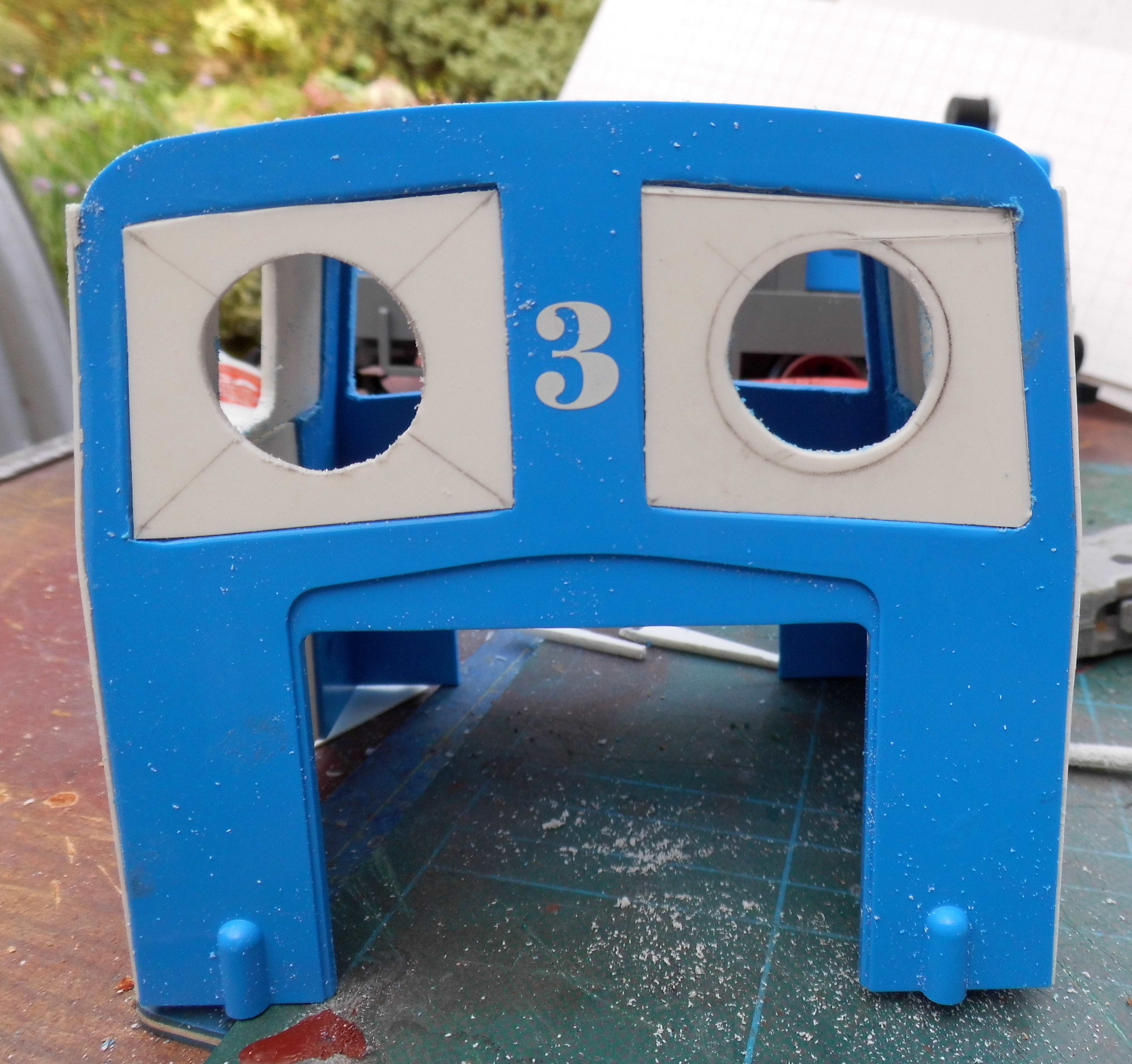
As I wanted to keep the three main body components intact (the front bonnet, the cab and the rear bonnet), I started with the cab, as I felt this would need the most modification. I decided the large square windows needed to be replaced with smaller spectacles.

Plasticard blanking pieces were cut to size .....


 ..... and then marked in the centre .....

..... to allow a 20mm diameter hole to be drawn.

This was then drilled out and filed to make a suitable spectacle window. The inserts were then glued into the square windows with high viscosity superglue.


The steps were tackled next.


 2mm thick plasticard was cut to widen the middle step and provide infill for the top step.


 The sides of the cab were closed-in with a sheet of 1.5mm thick plasticard cut to size. A window was cut.....


 ..... and a doorway incised into its middle.

The grille at the front of the bonnet ......

.... was removed by initially drilling some pilot holes and then using a razor saw.

A new grille was made from a frame of plasticard, .......

...... infilled with a piece of metal louvre for a flyscreen supplied by an Australian fellow garden railway modeller friend.

 Buffer beams were cut from 2mm thick plasticard......
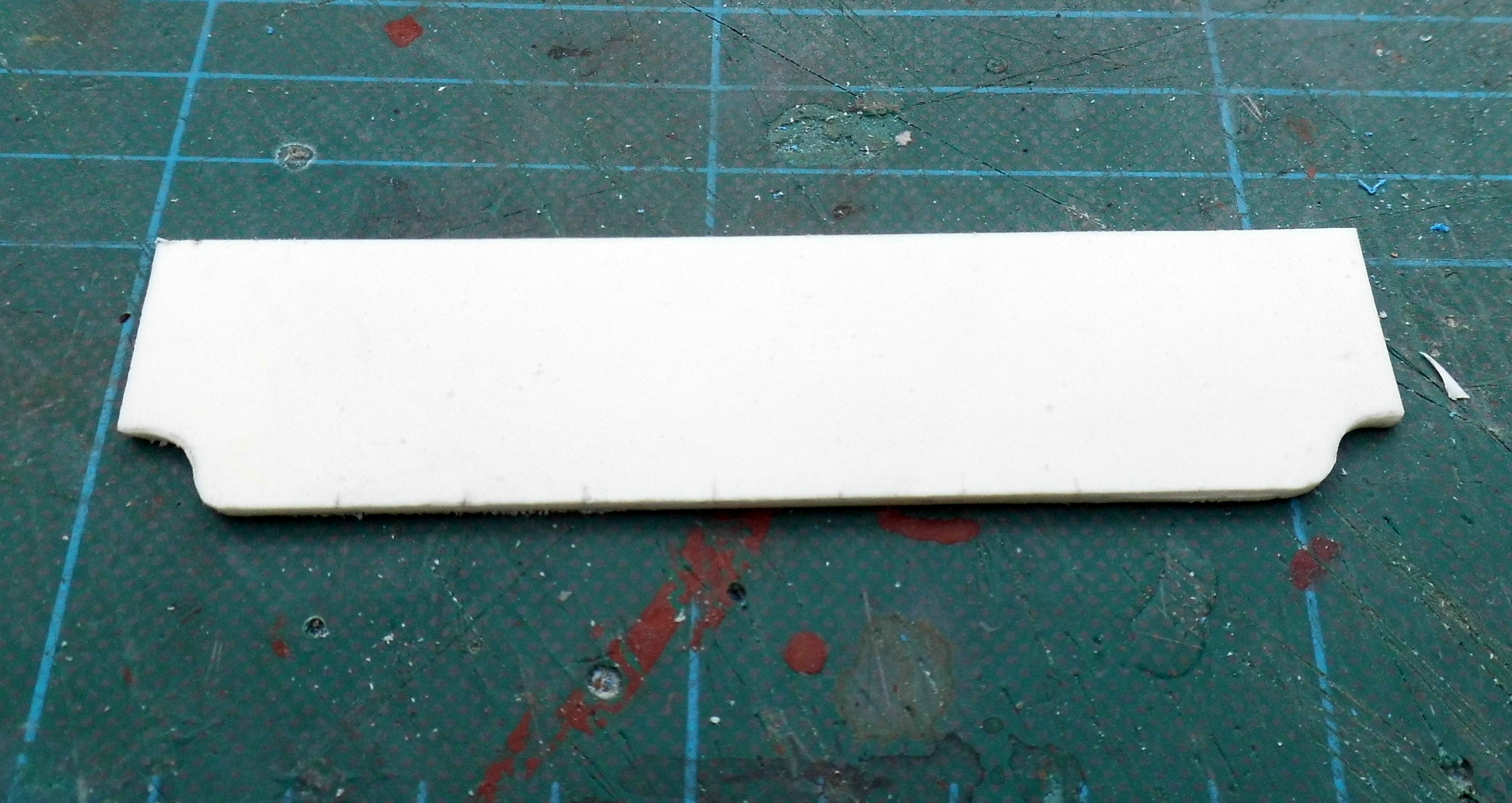
...... and glued to the front and rear of the running plate.

The sub-frame of the loco was then given a couple of coats of Halfords' grey primer from an aerosol rattle can.

 Similarly, the body-parts were given a couple of coats of grey primer from a Halfords' aerosol rattle can.


Once the primer had dried off, 1.5mm diameter half-round nail art gems were carefully applied to the body using dabs of superglue applied with a cocktail stick, to simulate rivet heads.


 The body parts were then given another couple of coats of grey primer.

The body was given a couple of coats of Rover Brooklands Green from a rattle can and the running plate and sub-frame given a couple of coats of Satin Black.


I decided to add a layshaft and fly-cranks to the loco. Whitemetal mouldings of fly-cranks were acquired from Garden Railway Specialists.

However, their pitch (ie the distance between the axle hole and the crank pin) did not match that of the loco wheels and so, the moulding was carefully cut to separate the crank pin.

 The two parts were then soldered back together, 3mm further apart, using low-melt solder. The parts were held in place with a simple jig - basically, two holes drilled in a piece of plywood; a large hole for the axle and a small hole with a brass pin inserted to hold the crank-pin in place.

Once I was sure the solder had hardened .......

...... the joint was tidied-up with a file.

A bracket for the layshaft was cut from a piece of 1.5mm thick brass and drilled along its centre line with 3.5mm diameter holes

This was then bent up into a U-shaped bracket, ......

 ..... and attached to the motor block with self-tap screws.

A new connecting rod was cut from 1.5mm thick brass sheet.

It was then filed to more closely resemble a connecting rod and fixed in place with self-tapping screws

Fibre tap washers of the correct diameter, .......

....... were glued around the spectacles and painted gold for surrounds.

 Handrails (from bent brass rod) were attached ........

........ as were an exhaust pipe with silencer and an air intake (whitemetal mouldings from GRS).

The loco was then given some extensive testing.

Although it is an ugly looking beast, I have decided that it could have been something which served in the trenches in the First World War. It certainly has a very utilitarian air. The tractor sound effects (downloaded from the internet) seem quite appropriate for this loco and so it has now formally joined the railway's motive power roster - as loco number 20 with the name Robert.

Originally, I used the loco as a test-bed for my experiments with Arduino Bluetooth control (see Arduino Bluetooth control - Part 1). However, I didn't like having to look at my phone screen while controlling the loco, and so I developed the system to make the loco radio-controlled using a hand-held transmitter.
 
For more information about the Arduino radio-control system, see How I built an Arduino based radio control system for a G Scale loco - pending
  

Friday, May 23, 2025

How I operate some of my points with wire in tube rodding

I had to replace the raised timber baseboard at Beeston Market as some of the boards had rotted (see How I replaced the baseboard at Beeston Market station) and while relaying the track, I decided that it would provide me with an opportunity to find a way of operating the points at the back of the layout remotely. I had tried it previously with Bowden (bike brake) cable (see Progress Report 82), but it proved unreliable as, eventually, dampness caused the cables to rust. Also, squirming around underneath the baseboard to install and maintain it wasn't easy or comfortable. So, with new baseboards and a revised track layout I started thinking of an alternative method for controlling the hard-to-reach points.

Previously, I had successfully used galvanised fencing wire to control the points leading to the storage sidings in the lean-to (see Operating turnouts with simple point rodding) and so, having plenty of wire available, I decided to explore using this to operate the points at Beeston Market.

Initially, I simply had lengths of wire running from the edge of the baseboard to the points with staples to guide them.


 While this worked well and was simple to install, I realised that I would need to find a way of protecting the wires when I added ballast to the track. After trying to think up ways of creating covers for the wires, I decided that it would be far simpler to have the wires running through tubes. A quick search on eBay resulted in the purchase of ten metres of 3mm internal diameter PVC tubing.

It would mean removing the first set of wires I'd installed, but that was a relatively easy job. So with plenty of wire and tubing to hand, I set to work.

 Firstly, I cut a length of tubing which would stretch from the edge of the baseboard to the relevant point. Where it passed under the platform, a slot was made in the underside of the platform. Similarly, some of the sleepers of intervening points needed to be slotted to allow the tubing to pass beneath.

 A length of the galvanised fencing wire was then cut with sufficient extra to allow one end to be bent upwards to slot into the end of the point's tie bar and for the other end to be bent into a loop. The tie-bar end of the wire was flattened slightly with a hammer to allow it to pass through the rectangular hole easily.

 The other end of the wire was bent around into a loop.


By the way, before the wire was threaded into the tubing, some 3in1 oil was squirted into the tube. As can be seen, galvanised staples were tapped over the tubing at intervals to hold it in place, making sure they didn't pinch the tubing to stop the wire from moving freely.

 All the points at the furthermost side of the layout have now been equipped with rodding, thereby making life a lot easier during running sessions. The next stage will be ballasting.