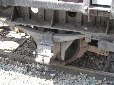
Having recently constructed a rake of nine hopper wagons based on those which ran on the Snailbeach and District Railways using Hartland Locomotive Works (HLW) wagon chassis (see How I constructed some Snailbeach hopper wagons) , I realised I would need to represent the brake gear - which on the Snailbeach wagons bore on two wheels on one side of each wagon. Many narrow gauge wagons had simple brake gear which only operated on one wheel, so the Snailbeach brake gear was going to be slightly more complicated.
After drawing up a sketch plan, based on the dimensions of the HLW wagon chassis based on drawings of the brake gear in Eric Tonks' book The Snailbeach and District Railways (Industrial Railway Society, 1974) .......

...... I decided that I would use thin brass sheet, rather than plasticard, for this construction as I thought the flimsy components might be susceptible to damage. Fortunately I had some thin brass shim available in my box of bits and so started marking and cutting out the various components. As I was fitting-out five wagons, I could batch-produce each component.
I started with the brake lever, which as you can see below, was 45mm in length and 3mm, tapering to 2mm wide, with a 1mm diameter hole at the 'thick' end.

I marked-out six levers, drilled them, cut them out and shaped the ends with a file for the five wagons (and one spare, just in case!).

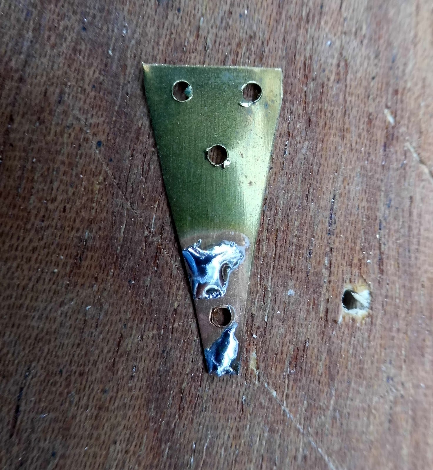
I then marked-out five pivot plates. The dimensions for each are shown on this drawing.

I find drilling the holes easier after marking out these small parts and before cutting them out, as it is easier to hold and position a large piece of brass than several small pieces. The holes, by the way, are 1mm diameter. I could have saved brass by marking these out back to back.

These were then cut-out. I actually used a robust pair of scissors rather than tin snips.
Next, I marked-out the droppers to support the brake operating linkage. As can be seen the droppers were, overall, 31mm x 3mm, with a 1mm hole drilled 2.5mm from the upper end of the dropper. The 5mm divisions at each end are where the droppers will be folded (see below).

Again, the droppers were marked-out, drilled and then cut-out in batches. I needed ten for the five wagons, but marked-out twelve - just in case!

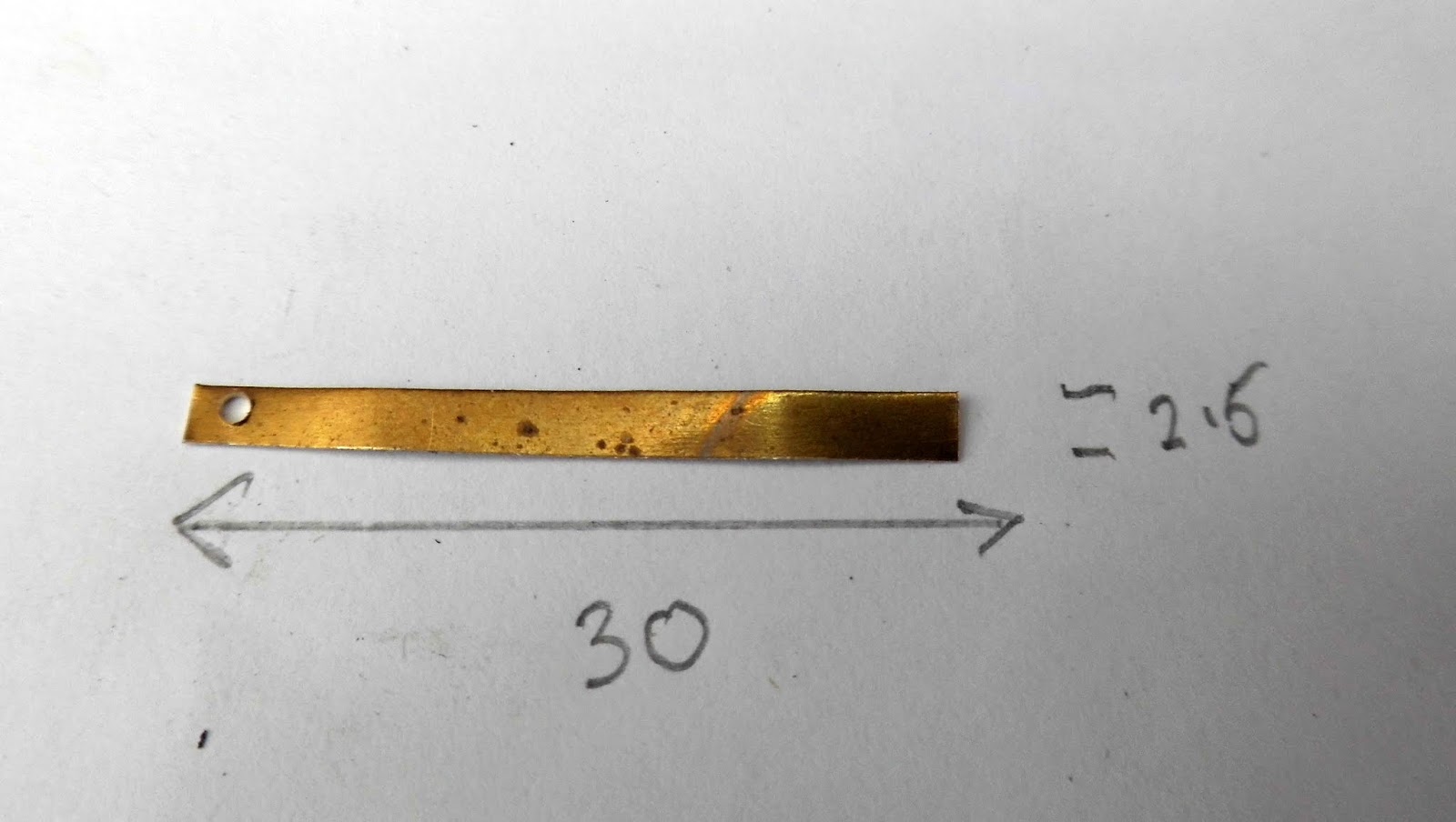
Next, I marked-out the linkages - 30mm x 2.5mm, with a 1mm hole 2mm from one end.

These were marked-out as a batch of twelve.

Finally, the brake shoes were marked out. These were 8mm x 4mm with a 1mm hole drilled in the centre of the 8mm side, approx 2mm in from the edge.

The concave surfaces were filed before each shoe was cut-out - again, it's easier to do this while the shoes are part of a larger chunk of metal.

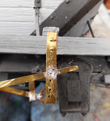
Now. armed with all the requisite bits and pieces, I was ready to solder them all together. As I don't possess asbestos finger-tips, I drilled a few holes in a piece of 8mm plywood to locate the various components. The holes coincided with the main components shown in the original sketch plan (see above) - two holes in the centre, 5mm apart. Either side of these were another two holes, one ??mm to the let and right, ??mm above the upper hole - and the other ??mm to the left and right, ??mm below the lower hole.

The various components were then tinned with solder at strategic points .....


...... before being located via the holes in the jig, using dome-headed, brass escutcheon pins.

Heat was applied to the various tinned joints .......

........ and then excess solder was filled clean with square needle file.

(Note: the guide for the brake-lever was soldered on last of all).
The three pins which had been soldered were then snipped off at the rear.

To fix the gear in place, one hole was drilled in the sole bar to coincide with the lowermost hole in the support plate. An escutcheon pin was then passed through the hole ........


..... and bent over to secure it in place.

This process was repeated with the other two holes in the plate.

The ends of the droppers were then folded over, a hole drilled through the longitudinal member, a pin inserted and then glued into place with superglue.

The guide for the brake lever was then fixed in place with a couple of pins .......

...... drilled and superglued into place.
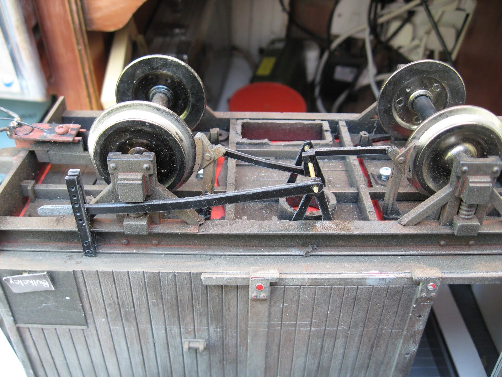
The gear was then given a coat of red oxide primer ........

....followed by a coat of black acrylic paint with the end of the brake lever picked-out in white.

The wagons were then weathered ........

......... and recoupled together in their rake and given a few test-runs.


As indicated above, I have constructed different versions of brake gear, dependent on the type of wagon for which they were intended. Some using plasticard components .....

... and others with vee-hangers using a combination of plastic and brass components.

I am intending to construct some single-wheel brake gear systems, based on those of wagons on the Welshpool & Llanfair Railway.


As they say, watch this space!!

After drawing up a sketch plan, based on the dimensions of the HLW wagon chassis based on drawings of the brake gear in Eric Tonks' book The Snailbeach and District Railways (Industrial Railway Society, 1974) .......

...... I decided that I would use thin brass sheet, rather than plasticard, for this construction as I thought the flimsy components might be susceptible to damage. Fortunately I had some thin brass shim available in my box of bits and so started marking and cutting out the various components. As I was fitting-out five wagons, I could batch-produce each component.
I started with the brake lever, which as you can see below, was 45mm in length and 3mm, tapering to 2mm wide, with a 1mm diameter hole at the 'thick' end.

I marked-out six levers, drilled them, cut them out and shaped the ends with a file for the five wagons (and one spare, just in case!).

I then marked-out five pivot plates. The dimensions for each are shown on this drawing.

I find drilling the holes easier after marking out these small parts and before cutting them out, as it is easier to hold and position a large piece of brass than several small pieces. The holes, by the way, are 1mm diameter. I could have saved brass by marking these out back to back.

These were then cut-out. I actually used a robust pair of scissors rather than tin snips.
Next, I marked-out the droppers to support the brake operating linkage. As can be seen the droppers were, overall, 31mm x 3mm, with a 1mm hole drilled 2.5mm from the upper end of the dropper. The 5mm divisions at each end are where the droppers will be folded (see below).

Again, the droppers were marked-out, drilled and then cut-out in batches. I needed ten for the five wagons, but marked-out twelve - just in case!

Next, I marked-out the linkages - 30mm x 2.5mm, with a 1mm hole 2mm from one end.

Finally, the brake shoes were marked out. These were 8mm x 4mm with a 1mm hole drilled in the centre of the 8mm side, approx 2mm in from the edge.

The concave surfaces were filed before each shoe was cut-out - again, it's easier to do this while the shoes are part of a larger chunk of metal.

Now. armed with all the requisite bits and pieces, I was ready to solder them all together. As I don't possess asbestos finger-tips, I drilled a few holes in a piece of 8mm plywood to locate the various components. The holes coincided with the main components shown in the original sketch plan (see above) - two holes in the centre, 5mm apart. Either side of these were another two holes, one ??mm to the let and right, ??mm above the upper hole - and the other ??mm to the left and right, ??mm below the lower hole.

The various components were then tinned with solder at strategic points .....


...... before being located via the holes in the jig, using dome-headed, brass escutcheon pins.

Heat was applied to the various tinned joints .......

........ and then excess solder was filled clean with square needle file.

(Note: the guide for the brake-lever was soldered on last of all).
The three pins which had been soldered were then snipped off at the rear.

To fix the gear in place, one hole was drilled in the sole bar to coincide with the lowermost hole in the support plate. An escutcheon pin was then passed through the hole ........


..... and bent over to secure it in place.

This process was repeated with the other two holes in the plate.

The ends of the droppers were then folded over, a hole drilled through the longitudinal member, a pin inserted and then glued into place with superglue.

The guide for the brake lever was then fixed in place with a couple of pins .......

...... drilled and superglued into place.

The gear was then given a coat of red oxide primer ........

....followed by a coat of black acrylic paint with the end of the brake lever picked-out in white.

The wagons were then weathered ........

......... and recoupled together in their rake and given a few test-runs.


... and others with vee-hangers using a combination of plastic and brass components.

I am intending to construct some single-wheel brake gear systems, based on those of wagons on the Welshpool & Llanfair Railway.


As they say, watch this space!!

No comments:
Post a Comment