Thursday, August 15, 2024

Progress Report 99


I can't believe it's been nearly nine months since I last wrote a progress report. It's not as if very little has been happening, I suppose it's just that I've been very busy.

Since my last report, three new locos have joined the fleet and another loco is in the process of being constructed. I've experimented with and developed a couple of different powered chassis for locos, I've tried out a couple of new cheap soundcards. I've had a few running sessions and made a few videos. I've hosted visits from fellow modellers and carried out running repairs on locos, stock and pointwork.


Rolling stock

 Locomotives

Since my last report, I've become very interested in early paraffin/diesel locomotives and as a result constructed a couple.

HGLW/Gmeinder diesel

I spotted a Houston Gate Loco Works (HGLW) kitbuilt loco being offered at a bargain price on eBay and so decided to invest in it.


I've constructed an HGLW loco previously (see How I constructed an HGLW loco from a kit) and bashed another (see How I added radio control to an HGLW loco) and I like their robust construction and bulletproof powered chassis.

Once it arrived I set about enhancing it, but when it was nearing completion I had a change of heart - it somehow didn't look right.


 I scoured the internet for a centre-cab diesel loco which could inspire a scratch-bash, and stumbled across what turned out to be a (poorly) preserved narrow gauge Gmeinder diesel loco which looked promising.

I moved the cab so it was off-centre and designed and 3D printed the additional components, most notably the two curve-topped bonnets.

The loco has now been completed and joined the fleet as Gmeinder loco No. 26 James.

 For more information, see - How I enhanced a basic HGLW kit loco


Ruston 44/48HP(ish)

The next loco I tackled started off using a pencil sketch of the Rev. Awdry's Rusty loco and initially, using the same HGLW powered chassis as James above.

As there were no dimensions shown on the drawing, I based them on the wheelbase of the HGLW chassis and worked outwards. 

However, once I had finished the body shell and fitted it to the HGLW chassis, it just didn't look right.

The loco sat too high above the track. So, it was back to the drawing-board. 

At first, I toyed with somehow reducing the height of the HGLW chassis - but that would have meant a complete rebuild - and so, I decided it was time to produce my own powered chassis, specifically designed for the loco. After a considerable amount of head-scratching, prototyping, redesigning and tinkering, I produced what I feel is a powerful, workable and (hopefully) reliable powered chassis.

The loco now, to my mind, looks far more realistic even though, as I have now discovered having bought the excellent booklet on narrow gauge Ruston locos from the Moseley Railway Trust, it is not really to scale.

For more information on this build, see How I constructed a Ruston(ish) diesel loco.


Ruston Proctor

 Whilst trying to track down photos and drawings of the Ruston, I stumbled across an earlier diesel loco which looked very attractive, and so I felt the need to make a model of a Ruston Proctor paraffin loco.

Once more, I was then unable to track down any scale drawings, but my web searches had unearthed a Gn15 file for the loco on the Shapeways website. At around £16GBP, it seemed reasonable and so I forked out my cash and invested in the .STL file.

Unlike my own 3D drawings, which breaks down a model into a series of separately printable sections, this was a single file of the whole loco. Something I've not tackled before.

I ended up printing it on my resin printer, and scaled it up so I'd be able to fit one of my own powered chassis into it.


A fair bit of tweaking was required to adapt the body shell to take the chassis and provide sufficient room for the batteries, radio control equipment and soundcard. As a consequence, the model is slightly over-scale. However, to my mind it is redolent of the original and I'm looking forward to having it take a part in my next video.

For more information see How I constructed a Ruston Proctor locomotive


De Winton vertical-boilered loco

I have always been attracted to de Winton vertical boilered steam locos and when the 3D printable parts for one appeared on Thingiverse, downloaded them, adapted the chassis for 45mm gauge and put it together.

However, it didn't look quite right and when a fellow modeller on the gardenrails.org forum alerted me to the fact that a three-foot gauge de Winton loco was on display in the foyer of Caernarfon station I took a trip with a camera and tape measure and returned with enough information to draw my own 3D parts.

These were printed out and, after a fair bit of redesigning, tweaking and fettling, I have now produced a passable working model of a three-foot gauge de Winton loco.

For more information see How I designed, 3D printed and constructed a three-foot gauge de Winton loco - pending


Powered loco chassis

Until now, I have avoided making my own powered chassis, preferring instead to use commercially produced motor blocks. Many years ago, I did try making my own powered chassis, but they weren't very successful as I lacked the skills and equipment for turning out precision cut and drilled parts for aligning axles, wheels and gears. However, when it was pointed out to me that 3D printers can produce parts to around 0.4mm tolerances, I decided it was time to give it a go.

Since designing and printing my first chassis for my Glyn Valley Beyer Peacock loco .....

I have now developed a more generic design, which I have successfully used in my recent diesel loco builds.

The de Winton loco has a bespoke powered chassis to fit the restricted space available.

My next planned design will be for a motor block suitable for steam locomotives once I have identified a reliable source of spoked wheels with cranks.

For more information see How I constructed my own motor blocks - pending


Soundcards

Over the years, I have used a range of different soundcards in my locos - Dalee, Phoenix and MyLocoSound. In addition, I have played around with various MP3 players (eg see How I used a cheap MP3 players as a soundcard) and cheap sound recording modules (eg see How I used a cheap greetings card sound module as a soundcard) . I have also  tried using Arduino (see An Arduino controlled MP3 player

 Recently, I have discovered some cheap diesel soundcards on AliExpress which work well

However, most of my experiments have been focused on the reproduction of diesel sounds. I haven't, as yet, explored recreating steam sounds other than with the cards mentioned above. At some point, I aim to see what is achievable with Arduino for simulating steam sounds.


 Operation

Running sessions

I've had surprisingly few running sessions since the last update. I don't tend to operate the railway during the winter, but the wettest spring since records began has literally dampened any enthusiasm for running trains.

However, I have managed a few sessions which have resulted in videos.


In addition, I took the opportunity to take a few still photos of the railway in action.
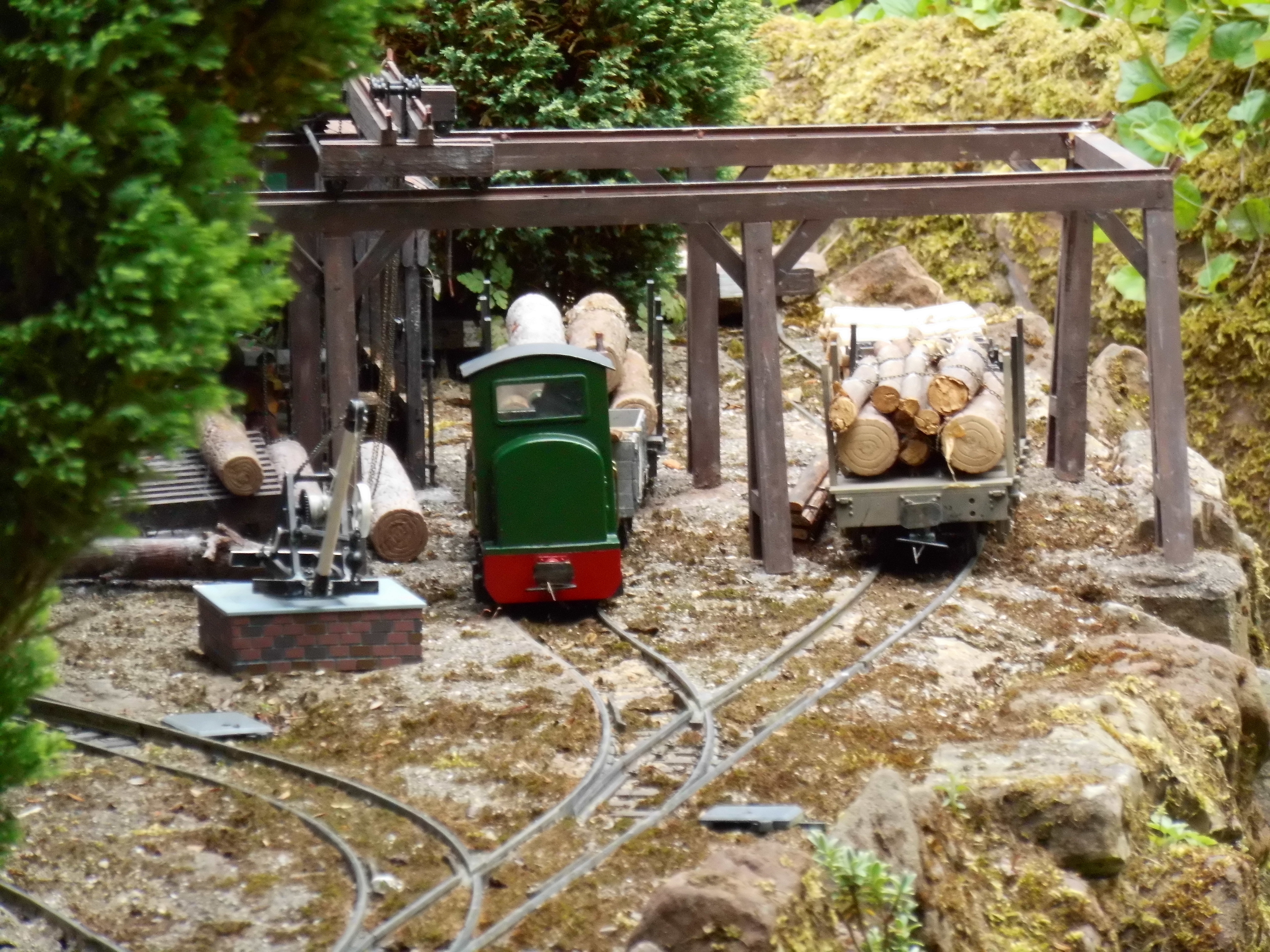
Gmeinder diesel James shunting at Peckforton sawmill

A view of Beeston Castle station with the sand quarry siding in the foreground

The pickup goods arriving at Beeston Market station

Black Hawthorn loco No.14 Burwardsley shunting at Beeston Brewery

Barclay loco No.2 shunting at the Boneworks

Running maintenance.

As with their 12 inch to the foot scale counterparts, model railways are in constant need of repair and maintenance. The PLR is no exception.

Loco maintenance 

In the casualty bay at the moment are:

  • Simplex loco No. 12 - Emma - awaiting a replacement soundcard
  • Manning Wardle loco No. 6 - Harthill - motion in need of easement
  • Hunslet loco No. 25 - Tattenhall - motor block needs repair and lights need rewiring
  • IP Engineering loco No. 9 - Lolly - Needs new NiMh battery plack

These will be repaired once other outstanding projects have been completed


Points operation

 I was finding that the Deltang controller which I used for changing points by radio control (see How I control some of my points via Radio Control) has lost sensitivity, meaning that I could only use the transmitter when close to the receiver which is mounted in the leanto beside the house. Closer inspection revealed that the double-glazed window behind which the received was placed has misted up and was interfering with reception. A quick email to Andy at Micron, resulted in a compatible replacement receiver with a 40cm extended aerial, which I was able to poke out of the opening light above the affected window. Normal services have now been restored .


 Infrastructure 

More 3D scanned figures. 

The second batch of scanned 3D figures of cast members from our local Amateur Drama Society in 1930s attire have been received and are in the process of being painted. They have so far been primed with black primer and will then individually be painted in acrylics. These figures depict people engaged in activities rather than waiting for trains.


They will probably take at least another six months to complete, as painting them is very time-consuming, and I generally fit their priming and painting in around other projects.

Monday, July 08, 2024

How I constructed a Ruston Proctor paraffin locomotive


Having constructed a fairly ordinary Ruston diesel (see How I constructed a Ruston(ish) diesel locomotive), during my researches about it, I was very much attracted to the very early Ruston Proctor paraffin locomotives and felt a strong desire to construct one.

As with the Ruston, I was unable to track down any scale drawings (which has since been remedied - manyfold!) and so had to base my construction on photos. However, my internet searches yielded a downloadable 3D printing file for a Ruston Proctor loco in Gn15 scale on the Shapeways website. At around £16GBP, this seemed like reasonable value, and so I delved deeply into my pockets (well my PayPal account) and purchased it.


 Unlike my own 3D drawings, where I break down a model into separate components which can be printed flat on the print-bed, this download comprised a single .STL file of the whole locomotive. This was completely unknown territory for me, and so I wasn't quite sure how to proceed.

The file was too large and complicated to import into TinkerCAD, so I was unable to break it down into sections. I loaded it into Photon Workshop, the slicer for my AnyCubic Photon resin printer to check its dimensions. As I wanted it to run on 45mm gauge track, I decided it needed to be enlarged - although Gn15 locos are supposedly G Scale (c1:20), they are designed to run on 16.5mm gauge track and so (as in this case) it would probably be a bit too narrow.

At around 46mm wide, I felt it was a bit too narrow for 45mm gauge. I'd not seen images of the inside framed three foot gauge Ruston Proctors at this stage and assumed it would be outside framed. And so, .......

...... I decided to enlarge it sufficiently to fit over one of my bespoke 3D printed powered chassis (see How I designed, drew and 3D printed my own powered chassis). 
 

 I widened the model to 65mm and increased its overall proportions to match.


 I recognised that this would now no longer make it a scale model of the original, but felt it is in keeping with the design. All my models are based loosely on their originals, and so exercise the rubber ruler principle. Besides, making it larger would allow me to fit the batteries, radio control, soundcard etc.

Once it had finished printing, I needed to do a fair bit of tidying to remove all sign of the supports. I was then faced with the problem of modifying the body shell to fit the chassis.

I felt justified as, once I did track down some images of the loco, quite a few compromises had been made to enable it to fit its 00 powered chassis. The Shapeways version did not, for example, continue the curved cab sides across the inside of the cab which is quite a predominant feature of the original loco - and also provides a great way to hide the mechanism.

The missing parts were drawn in TinkerCAD and printed out.

...... as were new side frames.

The body was then reassembled and given a couple of coats of Halford's rattle can filler primer.


The electrics were wired-up using my tried and tested circuitry and a Deltang compatible Micron MR603 receiver controller and a cheap diesel engine soundcard from AliExpress.

Click to enlarge

Incidentally, the soundcard needed a servo signal input - so the MR603 was reprogrammed to provide this on Pad 3. See How I use cheap diesel soundcards with Micron MR603 receivers

Once it had been successfully test-run strips of lead flashing were crammed into every available nook and cranny and the loco was taken through the paint-shop and given the default PLR livery of Rover Brooklands Green from a Halford's rattle can aerosol.

 It has been assigned the number 26 and given the name, Greg, after my garden railway modelling friend who lives in Sydney.

 With the addition of buffers, couplings, a driver and some controls in the cab, it has now entered service.


 I've not yet decided how it will be deployed, but for now I reckon it will often be found pottering around the sidings at the sand quarry, with occasional forays into Bickerton Station.
 

Sunday, July 07, 2024

How I constructed a Ruston(ish) diesel loco using a HGLW deluxe chassis kit

 After enhancing a Houston Gate Loco Works kit which I bought cheaply off eBay (see How I enhanced a basic HGLW loco kit) .....

..... I decided to have a go at constructing one of the neat little Ruston diesels which extensively pottered around various narrow gauge railways in the UK (and beyond). Having no drawings available, I scoured the net and eventually tracked down a pencil sketch of "Rusty" - one of the Rev. Awdry's Scarloey Railway locomotives.

I decided to base it around the ubiquitous Houston Gate Loco Works deluxe powered chassis as I was familiar with it, it is a tried and tested design and relatively cheap to buy. 

Having duly purchased the chassis kit online, I set about constructing it.

The instructions are clear and easy to follow and the laser-cut MDF parts, wheels, axles, gears, motor and electrical components needed are provided.

The first task was gluing the motor mounts to the cross-member .....

..... followed by the brake gear.

Then, one side was glued to the running-plate .....

.... followed by the other, trapping the cross member between them.

The ends of the chassis were then attached.

Following the instructions, two washers and the bearing bushes were slid on to the ends of the axles.

Next, the various components for the axle boxes were removed from the fret.


The spring hangers and axle boxes were glued on first, ....

...... followed by the axle box cover.

This process was repeated for all four axle boxes.

Semi-round nail-art gems ......

were then glued on to the brake hangers .......

..... axle boxes ......

..... and the irons.

My technique for applying the gems is to place a small blob of thick superglue on the desired locations, using a cocktail stick.

I find there is usually sufficient residue of glue left on the cocktail stick to allow me to pick up one of the gems and place it on the blob of glue. The blob is sufficiently more attractive than the residue on the stick, and so the gem is transferred easily on to the model.

Once all four axle boxes had been successfully adorned .......

..... the wheelsets with their bearings, were lowered in to the slots on either side of the chassis.
NOTE: The rubber O-Ring was left lying loosely over the axles at this point.


The axle boxes were then glued into place, making sure none of the glue came into contact with the bearings or axles.

This process was repeated until all four axle boxes were attached.

The O-Ring pulley could then be slid over the pulley wheels. I find this simple four-wheel drive mechanism to be very effective in practice.

The motor mounts were slid over the motos ......

..... and the motor screwed into place, using the screws provided.

As the holes for the screws are slotted, it was then possible to adjust the position of the motor, so the worm would mesh perfectly with the worm-wheel. I found attaching a 3v battery to the motor useful, so the motor position could be tweaked until there were minimal grinding sounds coming from the gears.

In the meantime, I had been busily designing, drawing and 3D printing the parts needed for the body. As the drawing of Rusty provided no scale or dimensions, I based the scaling around the HGLW chassis. I have since discovered that this means the loco is slightly larger than it should be - so maybe I will (one day) go back and redraw the parts to a more accurate scale using my own chassis (see below).

Once I had gathered all the parts of the body together, the first task was to remove the springs from above the axle-boxes on the chassis, so the body could slot over it.

I also needed to slightly widen the hole in the running plate for the motor with a file to enable it to fit.

The rear of the cab was glued into place first. The position of the cab front and rear are predetermined by slots and pegs which I included in the 3D drawings. 

Incidentally, I used EverBuild High Viscosity superglue for the construction of both the chassis and the body. It has the advantage of giving an almost instantaneous bond, especially if used in conjunction with an activator spray (all available from Tool Station).

The cab sides were then glued into place.


Then, the cab front was glued into place.

Next, the support for the fuel tank was attached in front of the cab, .......

..... allowing the tank to be glued on to it.

The ends of the tank were then glued on.

The bonnet was then attached, .......

..... followed by the bonnet cover.

The main part of the radiator was then glued on to the front of the bonnet, .......

...... followed by the two side pieces.

And finally, the top of the radiator was glued into place.

The body was then united with the chassis.

However, I wasn't very happy with its appearance. By this time I had tracked down some photos of actual Ruston locos, and it was obvious they sat a lot more closely to the rails than the HGLW chassis would allow.

It was time for a rethink.

Until now, I have fought shy of constructing my own mechanisms and chassis. Those I have constructed in the past have been only partially successful - or completely unsuccessful. However, fellow modellers on the gardenrails.org forum persuaded me to have a go at making my own chassis. The greatest problem I have faced previously with making powered chassis is my lack of precision when it comes to metalwork. Unless holes for axles are precisely aligned, then problems will ensue. But why make them from metal? Why not plastic? After all, the vast majority of commercial powered chassis and motor blocks I have used until now have used plastic mouldings for their main structures! And so, with a great deal of experimentation, trial runs, dead ends, redesigns and tweaking, I came up with a chassis which seems to be reasonably reliable and actually works! (see How I designed and developed my own powered loco chassis - pending)

Using this as a basis, I was able to mount the body much lower on the chassis

To my mind, although not strictly to scale, the loco looked a lot more realistic.

Furthermore, the powered chassis seemed to do what was required of it!

Buoyed with that success, the loco was taken through the paint shops and emerged in PLR livery, numbered 27, and given the name  'Nick' - another member of my "Old Gits' Friday Ambling Group (OGFAG)".


 It was also equipped with Micron Radio Control (compatible with Deltang) and a very cheap Chinese recordable soundcard on to which I uploaded the sound of a real Ruston chugging past.

For those who are interested, I have provided more information on how I designed, developed and produced my 3D printed powered chassis (pending) and the soundcard.