One of the great built-in features of the Deltang Rx65b receiver/controller is that it includes, as standard, auto-station stop, auto-shuttle and auto-buffer stop. A reed switch, mounted on the loco and connected to one of the pads on the Rx65b will trigger the effect wherever you want it to happen on your railway.
Having previously programmed a Deltang Rx65b receiver for auto-shuttle using a Prog4 Programa module (see How I programmed Deltang Rx65b for auto-shuttle), I decided I wanted to program the receivers in a couple of my locos for auto station stop so the locos would run around the railway slowing down and stopping at each station briefly before accelerating away again.
Although I like to run my railway prototypically with timetabled passenger trains and goods trains managed by a computerised freight management program (see A typical operating session), there are occasions when I just have a train running or two running around while I do some gardening or entertain family and friends with a barbecue.
Rather than using a Programa module, I thought it might be useful for others to see how the programming can be done with a Deltang Tx20 transmitter.

and Hunslet Loco No. 3 (Bickerton)

These were both constructed from GRS (Garden Railway Specialists) kits and both make use of the LGB ToyTrain 0-4-0 motor blocks. They are both powered by three 18650 li-ion batteries and both have Deltang Rx65b receiver/controllers fitted. As they are 0-4-0s, they don't have any pony trucks or bogies to become derailed and their mechanisms are very reliable. They are also both easy to dismantle to gain access to the receivers.

This is because its default setting is for Channel 1 servo output, which I seldom use, and also because it is close to the three negative pads one of which I would be using for a capacitor (see below).

Furthermore, I realised I could make use of the wiring system which was built into the motor blocks for the wheel pickups (see below)
 These can be bought cheaply on eBay (I think I bought 20 for £2.50 including postage). I soldered mine between Pad 8 and the nearest negative pad.

I then soldered a wire to Pad 8 and another wire to another negative pad (the grey wire on Pad 9 is being used as a trigger for a sound effect on the Dallee Sound Card).

The receiver was then shrouded in a shrink wrap sleeve.

I then removed the bottom plate of the motor block by unscrewing the screws holding it in place and re-installed the L-shaped metal connectors originally used for the track pick-ups. I bent up the last 10mm of these through 90º.

I then drilled a couple of 2mm diameter holes in the base plate after carefully measuring the location of the two metal 'spikes'. The base plate was then threaded over the spikes.

The spikes were then folded over and a reed switch soldered on to them.

An LGB push connector was soldered to the end of the (orange) wire leading to Pad 8 and the end of the negative wire was soldered to the central pin of a sub-miniature SPDT toggle switch. Another black lead was soldered to another of the pins and an LGB push connector soldered to the other end.
The switch was mounted discretely beneath the saddle tank
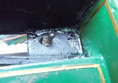
This switch will be used to disable the auto station stop feature by isolating the reed switch. This will enable be to use the loco for normal duties.
The LGB connectors were then pushed on to the ends of the old track pickup contacts protruding from the top of the motor block (the central orange and black wires). The other two wires connect the motor to the Rx65b.

The section I needed for the auto station stop is in Menu 3 under the heading Automation.
Looking at the third option in this section I noted down the series of codes I needed for the auto station stop:
Cross referencing this with the bottom row of the chart, you will see that each number instructs the receiver to do something:
Firstly the receiver in the loco was bound to the Tx20 by:
I was then ready for testing outside on the track. I fixed a magnet to one of the sleepers in the station area, fixing it down with a couple of twists of wire. When I ran the loco over it, nothing happened. I then attached another magnet to the first, thus doubling its height (and increasing its strength) and this time the loco coasted gently to a halt as it passed over the magnet.
I then made a video of the next test run (my camera running out of battery at the last moment!
Other than that, deciding where and how to fix the reed switch is the next most difficult task. With a Tx20 (or even a Prog3), the actual programming is a breeze and probably the most satisfying part of the process.
The built-in auto capabilities of the Rx65b are a nice added bonus and it does seem a shame not to make use of them in some way. I hope this blog post encourages you to have a go.

Having previously programmed a Deltang Rx65b receiver for auto-shuttle using a Prog4 Programa module (see How I programmed Deltang Rx65b for auto-shuttle), I decided I wanted to program the receivers in a couple of my locos for auto station stop so the locos would run around the railway slowing down and stopping at each station briefly before accelerating away again.
Although I like to run my railway prototypically with timetabled passenger trains and goods trains managed by a computerised freight management program (see A typical operating session), there are occasions when I just have a train running or two running around while I do some gardening or entertain family and friends with a barbecue.
Rather than using a Programa module, I thought it might be useful for others to see how the programming can be done with a Deltang Tx20 transmitter.
The process
- Preparations
- Wiring up the receiver and reed switch
- Looking up the programming code
- Putting the receiver into programming mode
- Programming
- Testing
- Conclusion
1. Preparations
Before doing the modifications to the loco and the receiver, I needed to make a few decisions.
- Which locos was I going to use?
- Which output pad on the receiver was I going to use?
- Where was the reed switch going to be located on each loco?
Which locos?
Having fifteen battery powered / radio controlled locos at my disposal (see 2015 Loco Stock Roster), I had to decide which ones would be:a) the most reliable when left to their own devicesIn the end, I selected the two locos which were the among the earliest I added to the railway - Peckett Loco No. 1 (Peckforton)........
b) had sufficiently large batteries to be able to run for several hours
c) would be the easiest to modify.

and Hunslet Loco No. 3 (Bickerton)

These were both constructed from GRS (Garden Railway Specialists) kits and both make use of the LGB ToyTrain 0-4-0 motor blocks. They are both powered by three 18650 li-ion batteries and both have Deltang Rx65b receiver/controllers fitted. As they are 0-4-0s, they don't have any pony trucks or bogies to become derailed and their mechanisms are very reliable. They are also both easy to dismantle to gain access to the receivers.
Which output pad would I use?
I opted for Pad 8 on the Rx65b (shown in red).
This is because its default setting is for Channel 1 servo output, which I seldom use, and also because it is close to the three negative pads one of which I would be using for a capacitor (see below).
Where was the reed switch going to be mounted?
Another reason for choosing two locos which use the ToyTrain loco blocks was that their undersides have a recess which is ideal for mounting the reed switch.
Furthermore, I realised I could make use of the wiring system which was built into the motor blocks for the wheel pickups (see below)
2. Wiring up the receiver and the reed switch
This is probably the trickiest bit of the whole process. It needs a soldering iron with a small bit and a steady hand.Connecting a 0.1uF ceramic capacitor
To minimise the possibility of electromagnetic interference (EMI) disrupting the connection from the reed switch to the receiver a 0.1uF capacitor needs to be soldered from the output pad to the negative supply.

I then soldered a wire to Pad 8 and another wire to another negative pad (the grey wire on Pad 9 is being used as a trigger for a sound effect on the Dallee Sound Card).

The receiver was then shrouded in a shrink wrap sleeve.

I then removed the bottom plate of the motor block by unscrewing the screws holding it in place and re-installed the L-shaped metal connectors originally used for the track pick-ups. I bent up the last 10mm of these through 90º.

I then drilled a couple of 2mm diameter holes in the base plate after carefully measuring the location of the two metal 'spikes'. The base plate was then threaded over the spikes.

The spikes were then folded over and a reed switch soldered on to them.

An LGB push connector was soldered to the end of the (orange) wire leading to Pad 8 and the end of the negative wire was soldered to the central pin of a sub-miniature SPDT toggle switch. Another black lead was soldered to another of the pins and an LGB push connector soldered to the other end.
The switch was mounted discretely beneath the saddle tank

This switch will be used to disable the auto station stop feature by isolating the reed switch. This will enable be to use the loco for normal duties.
The LGB connectors were then pushed on to the ends of the old track pickup contacts protruding from the top of the motor block (the central orange and black wires). The other two wires connect the motor to the Rx65b.

3. Looking up the programming code
The codes needed for reprogramming Deltang receivers are located on the Deltang website. The programming chart for the Rx65b receiver controller is startlingly long - a reflection of the potential and complexity of this little technological marvel. It can seem a bit daunting at first sight, but it does actually make a lot of sense if you persevere with it.The section I needed for the auto station stop is in Menu 3 under the heading Automation.
| Automation | |||||
| 3 | 1-8 = P1-P8 |
8 = Buffer Stop [BUFFER1] |
Time to stop: 1-6 = 1-6 seconds |
Reactivate trigger: 1-6 = 10-60s (time to 'back out') |
ONE pad can detect external trigger to control H1 Action: Slow to a stop Close throttle to rearm (manual). |
| 3 | 1-8 = P1-P8 |
9 = Stop & Reverse [BUFFER2] |
Time to stop: 1-6 = 1-6 seconds |
Fixed pause time: 1-6 = 4,8,15,30,45,60s Random pause time: 7 = 4-8s 8 = 8-15s 9 = 15-30s 10 = 30-45s 11 = 45-60s |
ONE pad can detect external trigger to control H1 Action: Stop-Pause-Reverse (auto). |
| 3 | 1-8 = P1-P8 |
10 = Station stop and continue [BUFFER3] |
Time to stop: 1-6 = 1-6 seconds |
Pause time: As above |
ONE pad can detect external trigger to control H1 Action: Stop-Pause-Continue (auto). |
Looking at the third option in this section I noted down the series of codes I needed for the auto station stop:
3, 8, 10, 6, 11
Cross referencing this with the bottom row of the chart, you will see that each number instructs the receiver to do something:
- 3 = Menu 3
- 8 = Pad 8
- 10 = Auto station stop
- 6 = 6 seconds to slow down to a stop
- 11 = 45-60 seconds stopping before restarting
4. Putting the receiver into programming mode
I could have used a Prog4 (eg see Programming with a Prog4), a Prog3 eg see Programming with a Prog3) or a Tx20 (see Programming with a Tx20). I opted for using a Tx20 as this is my preferred programming technique. I find it to be the quickest and easiest method, particularly for a relatively simple programming task such as this.Firstly the receiver in the loco was bound to the Tx20 by:
- switching on the receiver
- waiting for around 15 seconds until it went into bind mode (its LED flashed rapidly).
- holding down the bind button on the transmitter
- switching on the transmitter (with the bind button held down)
- releasing the bind button
- waiting until the LEDs on the receiver and the transmitter stopped flashing to show they were now bound
- switching off the receiver
- holding down the F1 (Channel 2) and F2 (Channel 4) button on the Tx20
- switching on the Tx20 (with the buttons still held down)
- switching on the receiver
- checking that the receiver was in programming mode (signified by very rapid flashing of its LED)
- releasing the buttons on the Tx20
5. Programming
The LED on the Rx65b was flashing once per second. This showed it was ready to receive instructions for Menu 1. As I wanted to change items under Menu 3:- I clicked the Direction Switch on the Tx20 in the REVERSE direction.
- The LED on the Rx65b flashed rapidly
- When I returned the Direction Switch to the central NEUTRAL position the LED started flashing twice per second.
- I then flicked the Direction Switch in REVERSE once more and returned it to NEUTRAL
- The LED on the Rx started flashing three times. This meant it was ready to receive instructions for Menu 3
- I flicked the Direction Switch to the FORWARDS position and back to NEUTRAL to confirm that was what I wanted.
- I flicked the Direction Switch in the REVERSE direction 7 times to increment the flashes (pausing between each flick of the switch and sometimes counting the number of flashes to see how far I had reached)
- I checked that the LED on the Rx65b was flashing 8 times
- Then I clicked the Direction Switch in the FORWARDS direction to confirm this setting
- I flicked the Direction Switch in the REVERSE direction 9 times to increment the flashes (pausing between each flick of the switch)
- I checked that the LED on the Rx65b was flashing 10 times
- Then I clicked the Direction Switch in the FORWARDS direction to confirm this setting
- I flicked the Direction Switch in the REVERSE direction 5 times to increment the flashes (pausing between each flick of the switch)
- I checked that the LED on the Rx65b was flashing 6 times
- Then I clicked the Direction Switch in the FORWARDS direction to confirm this setting
Finally, the Rx65b was waiting to be told how long the loco would wait in the station before resuming (ie 45-60 seconds, represented by 11 flashes) and so:
- I flicked the Direction Switch in the REVERSE direction 10 times to increment the flashes (pausing between each flick of the switch)
- I checked that the LED on the Rx65b was flashing 8 times
- Then I clicked the Direction Switch in the FORWARDS direction to confirm this setting
At this point the LED on the Rx65b remained on steadily, showing that it had processed all the information I had just given it. The loco was now ready for testing.
6. Testing
Bench testing came first. Once I had checked all the wiring was correct, I powered up the loco and inverted it. I used the transmitter to get the wheels to start rotating as if the loco was moving forwards. I then waved a magnet over the reed switch and to my delight (and relief) the wheels slowed and stopped. After around 50 seconds, the wheels started rotating once more. All seemed to be fine. I tested it another couple of times, at different speeds and with the wheels rotating in reverse.I was then ready for testing outside on the track. I fixed a magnet to one of the sleepers in the station area, fixing it down with a couple of twists of wire. When I ran the loco over it, nothing happened. I then attached another magnet to the first, thus doubling its height (and increasing its strength) and this time the loco coasted gently to a halt as it passed over the magnet.
I then made a video of the next test run (my camera running out of battery at the last moment!
Conclusion
The most difficult part of this modification is, as has been stated, soldering the leads on to the receiver. I would suggest, if you are not confident with handling a soldering iron, that you ask someone who is to do it for you as a favour. When I was running RC Trains, I had a couple of receivers returned to me which had suffered damage because people had overheated them with soldering irons. The PCB tracks on the Rx65b are quite delicate and can easily be broken if too much heat is applied.Other than that, deciding where and how to fix the reed switch is the next most difficult task. With a Tx20 (or even a Prog3), the actual programming is a breeze and probably the most satisfying part of the process.
The built-in auto capabilities of the Rx65b are a nice added bonus and it does seem a shame not to make use of them in some way. I hope this blog post encourages you to have a go.
No comments:
Post a Comment