Tuesday, February 24, 2015

How I built some storage roads in the garage

For about the past five years I have been storing my stock in boxes which I have carried in and out of the leanto (see How I made some stock boxes)

This was a good solution at the time, as each box was matched to a siding on the railway and I was able to remove goods stock in its exact location at the end of a running session and replace it at the start of the next - freight operations are one of the things I enjoy about running my railway.

However, the disks in my neck have been giving me health problems which are exacerbated when I lift, twist and carry things - such as loaded stock boxes. It looked as if I needed either to find an alternative method of storing stock or abandon my railway.

Before we built a new garage, the station at Beeston Market was terminated by the fence which separated the front and back gardens.

The position of the newly built garage led to the removal and repositioning of this fence - but also opened up an opportunity to extend the station.

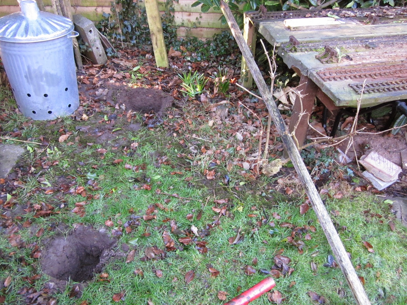
 I  decided, that if the extension to the station was angled towards the garage (see clothes prop lying on the ground in the above photo), I would be able to run a line into the garage.

Having decided on the geometry for the extension, I dug a couple of holes for the support posts.

 Two posts (recycled from the boundary fence) were cut to length and concreted into the holes (see How I mix concrete).

 A framework was then made for the baseboard, using the palings recycled from the removed fence (which incidentally was erected 34 years ago).

 When the framework was completed ........

...... it was boarded with more palings .........

...... and given a liberal coating of wood preservative.

It was then covered in roofing felt (tar paper), the edges glued in place with bituminous roofing adhesive.

The baseboard was now well placed for a spur to lead into the garage.

A chance meeting with the builder who constructed the garage resulted in a 4.5inch diameter hole appearing in the garage wall in the position needed.

 When I had erected the storage shelving in the garage, I had ensured that the lower shelf coincided approximately with the railway baseboard for just such an eventuality as this.

 However, a 4.5inch hole was never going to be large enough, and so the largest item of rolling stock was used as a template ......

..... for enlarging the hole. In addition, I needed to angle the hole in the same direction as the plank bridge leading up to the hole. On reflection, the 'pilot' hole should have been more central to the planned hole - but hopefully this will help you avoid my mistake should you want to follow in my footsteps.

A long 10mm masonry bit was used to drill a series of holes around the perimeter of the envisaged tunnel mouth. These were then linked together by drilling downwards and upwards from each hole.

The hole was then knocked through with a hammer and cold chisel. The pilot hole proved invaluable at this point in allowing the debris to be removed.

The Thermalite blocks inside were much easier to shape, with a saw.

 Clearances were checked and some fine tuning was carried out with the chisel, a hacksaw blade and a rasp. Unfortunately, when I plugged in my angle grinder, there was a blue flash and a puff of smoke, otherwise I would have tidied up the hole with it. Maybe Santa will bring me a new one.

Four pieces of 2"x1" treated timber formed the tunnel portal into which a flap, made from a couple of pieces of fence panel, was hinged.

The plank bridge was cut to size and made to sit on the lower edge of the frame for the flap. The other end resting on another piece of 2"x1" timber.

The end of the outermost former engine-shed siding was extended (to make a carriage siding) and then run across the plank bridge.

 Once inside the garage, the track divided into three using a couple of R1 points (turnouts) which were recycled as part of my ongoing upgrading of the main line - replacing all R1 points with larger radius points (see Progress Report 51 for example).

 The ends of the track on the plank bridge were aligned by soldering two short lengths of 2mm outside diameter (OD) brass tubing and using a bent galvanised nail as a bolt. 

Unfortunately, because the air temperature was low and there was a stiff breeze, it was difficult to heat the rail, even with my 75watt soldering iron, and my soldering was not as neat as I would like. In the balmy days of summer, I will re-solder these joints.

At this point, some stock was run in and out of the garage to ensure the clearances were sufficient.

Rather than splashing out on expensive track for the storage roads, I opted for a cheaper method - using 4mm x 12mm stripwood.

Two pieces, mounted on top of each other, provided the rail, which were notched to align with the brass rail.

To avoid splitting the stripwood, 1.5mm holes were drilled to take the brass panel pins.
 A track gauge (lying on its side behind the drill) was cut to ensure the rails kept to the right gauge.

Sleepers made from the stripwood lifted the wooden rails to the correct height, before it was then gently lowered to shelf-height.

To tidy-up the original pilot hole, a Thermalite plug from the original 4.5" bore was shaped with a saw and will eventually be concreted into place.

The wooden sidings were extended across the full width of the garage which gives me around 50' of storage space. This allows me to store all my goods and passenger stock with a few feet left for later expansion of the fleet.

All the stock has now been test-run in and out of the garage. This required a little tweaking here and there to provide sufficient clearance and in places the wooden rails needed to be re-gauged, but otherwise all now seems set for operations.

 Meanwhile, outside, the second former engine shed road has been extended to form another carriage siding and the platform roads extended into the newly positioned engine shed. There is still a lot of landscaping to do - a coaling stage and water tower will be added to the platform road leading to the shed and a station forecourt will be made towards the back of the board.


And, of course, I will need to find somewhere to store all the junk which was on that shelf in the garage. But hopefully, this work will ultimately help to save my neck from further damage..........


Thursday, February 05, 2015

How I converted Bachmann Jackson Sharp coaches into Leek & Manifold (ish) coaches

When I first constructed my garden railway, I acquired some temporary rolling stock which I could run immediately 'off the shelf'. In most cases, I have either converted this early stock into something more appropriate for a UK based narrow gauge railway or I have sold it on.


However, I kept a couple of of the Bachmann Jackson Sharp coaches with the intention of one day converting them into something which would not look out of place on my railway. Back in August 2014, I began the (as it transpired) laborious process of conversion.

The inspiration

What kick-started the conversion or - in my case, 'bash' - was a conversation on the G Scale Central (GSC) forum, in which someone requested the dimensions of the coaches which ran on the 2' 6" gauge Leek & Manifold Valley Light Railway in Staffordshire.
Leek & Manifold Railway Train - Source: http://collectionsonline.nmsi.ac.uk/detail.php?type=related&kv=226843&t=objects
 Previously, I had measured up the Bachmann coaches with a view to converting them into something resembling the Pickering balconied stock which ran (and now runs in replica form) on the Welshpool & Llanfair Light Railway. However, I abandoned this idea when none of the dimensions matched-up. Similarly, converting them into Southwold Railway stock was also a non-starter. However, when I acquired some drawings of the Leek & Manifold coaches, I worked-out that the windows on the Bachmann coaches could be adapted to resemble those on the L&M coaches. The length of the Bachmann coaches was shorter than the elegant L&M originals, but this was something I felt I could live-with. I knew that the Bachmann stock would happily negotiate the tortuous curves on my railway and so a quick (as I thought) mod would supply me with a couple of coaches to supplement my line's existing coaching stock.

I felt, however, that a rake of three coaches - two opens and one brake end - would be better suited to my railway, thus enabling me to run two passenger trains for occasions (such as market days and special excursions) when traffic would be heavier. A request on the GSC forum resulted in another coach kindly donated to the project by a fellow modeller.

Getting Started

The first job was to photocopy and enlarge the plans from Robert Gratton's excellent book on the Leek & Manifold. The plans were enlarged on to A4 paper (I am wary of working directly from the book in case it gets covered in glue or paint).

From these drawings, I was able to extract the key dimensions for the coaches.

The next job was to dismantle the coaches into their component parts. Fortunately, the coaches dismantled easily; the bogies were each held in place with a single screw, ......

 ...... four screws held the underframe to the body...........

 ...... which, once unscrewed, revealed the seating moulding, toilet cubical and stove; all of which simply sloted into place. Once these were removed, .........

..... the four screws holding the roof to the body were removed and the wires to the lighting bulbs were snipped.

The window castings were gently prised away from the walls and .......

........ the rest of the lighting circuitry was then dismantled. The brass connectors were put into the bits box - I'm sure these will come in handy one day in the future.

The upper part of the body moulding was then sliced with a razor-saw diagonally across each corner....

The overlapping lips were then sliced away from the sides by running a craft knife along the the inside of the angle a few times.

This left the bare-bones body skeleton.


Extending the balconies

 Firstly, the balcony rails were prised off.

 The outer holes were then filled with white putty and smoothed off. The inner holes were left unfilled.

The balconies were then cut away from the rest of the underframe, along the plank line adjacent to the steps.

 Two 10mm x 95mm x 1.5mm thick strips were then cut out and glued between the two sections of underframe.


These were then reinforced with longitudinal bracing strips.


The bodywork (Open coaches)

After consulting the drawings and photos, the windows which needed to be increased in width were identified (ie the second, third, sixth and seventh).
Leek & Manifold Open coach - source http://www.kachuzyn.fsnet.co.uk/coaches.htm
The width of the windows roughly equated to a single and a double window on the Jackson Sharp coaches whilst the height of each window on the L&M coaches was approximately equal to the complete height of the JS windows including the toplight.

The rebated strip above the windows was cut with a razor-saw to allow the height of the windows to be extended.

The rebated sections were then sliced horizontally, leaving a window bar which would eventually separate the main window from the toplight. Some offcuts of softwood were inserted inside the coach body to allow some pressure to be applied to the craft knife.

Once these panels had been removed, the edges were smoothed off with a file.

In the double sized windows, the body panels between the two windows were carefully cut away at the top .......

...... and base of each window. The bars separating the main window from the toplights were also removed.

 This left the coach sides with the correct number of single and double windows

The remnants of the panels on the double windows were then filed away with a slitting disc .....

 ...... and a file.

The vertical inner frames were also tidied up ......

.... with a flat file ........

....... to remove any remnants of the horizontal bars between main window and toplight. These were then sanded smooth with a light grade emery paper.

Several 12mm x 8mm rectangles of 1.5mm thick plasticard were cut out ........

...... and glued to the tabs between each window, to extend their height. After some experimentation, it was found that Plastic Magic solvent (from Deluxe Materials - https://www.deluxematerials.co.uk/en/rc-modelling/34-plastic-magic-5060243900210.html) could bond the plasticard to the harder plastic of the Bachmann coach.

These tabs were left to set while a piece of 1.5mm thick plasticard was cut to size with tabs 5mm long matching the window openings and a 5mm wide lintel to sit above the windows. An additional 40mm was added beyond the end of the coach side to project over the balcony.

This was glued on to the tabs on the coach sides.

Once these lintels had been attached along both sides, attention was turned to the ends which also needed to be extended in height. It was decided that the doors also needed to be increased in height. The door lintel ........

...... was therefore removed with a slitting disc

 ...... and then the door windows were enlarged with a flat file.

 A filler piece was then cut from 1.5mm thick plasticard with these dimensions.

This was glued into place on the end panels, with slots cut in the upper outside edges to take the extended lintels.

Although I left it until later in the build, in hindsight I would have finished-off the door frames with 2mm and 1.5mm thick plasticard at this stage - with some filler to disguise the join in between old and new panels. The frames were made an additional 5mm taller.

The grab rails were prised off at this point.

The uppermost hole could be filled at this stage (I left it until later), the stud and the lower hole are used later when the balcony rail is fitted.

The gable ends of the roof supports were tackled next. These were made to match the pitch of the roof and the width of the panels above the lintels.

A couple of pieces of 1.5mm plasticard were glued behind the lintels over the balcony - these were 39.5mm x 35mm .

The gable ends were then  glued to these .......

 ..... between the projecting side lintels.

 To create the angled edge on the lintels, 25mm x 2mm x 2mm strips of plasticard were glued just above the window openings (shown in black in the picture below).

8mm wide strips of 1.5mm thick plasticard were then glued on to these, .......

...... angled back at the top.

These were held in place with various clamps .....

 ..... until the solvent set.

Similar panels were then cut for the gable ends and glued into place in the same way.

This was done by eye, to take account of any slight variations in the geometry of the sloping side lintels.

The Bodywork (Brake End)

The construction of most of the bodywork for the brake end was as above, however, the window spacings are different and, of course, the luggage/guard's compartment needs to be constructed.
Leek & Manifold brake end. Source: https://chasewaterstuff.wordpress.com/2010/07/05/

As can be seen from the photo, the windows of the brake end are (from the balcony end) large, large, small, large, large, small. Once these had been identified and modified as above, there was sufficient room left for the luggage compartment. Firstly the two remaining windows were filled-in with 1.5mm thick plasticard. Gaps and the planking were then filled with white putty and when hardened smoothed down with emery paper.

The underframe was then attached to body and two pieces of 1.5mm thick plasticard, 12mm x 105mm and 15mm x 117mm were scored to represent planking and then fixed into place to take the bodywork up to and into the the recess for the steps. This was repeated for the other side.

 A further two pieces of 1.5mm thick plasticard, 35mm x 115mm were cut out and shaped to fit over the steps.

A window, 20mm x 35mm was cut into each piece, 35mm from the top and 12mm from the side.

1mm thick by 1.5mm wide pieces of microstrip (see How I make my own microstrip) were then attached to delineate the door opening. 5mm wide strips were also added along the top and just below the window.

Two 25mm x 40mm rectangles of 1mm thick plasticard were then cut out with 7mm frames were then cut out and glued behind the window openings.

The door panels were then glued on above the steps and a 123mm x 70mm piece of 1.5mm thick plasticard was cut out and shaped to match the slope of the roof. A 25mm x 37mm window was then cut into the middle, 48mm above the base.

1.5mm wide microstrip was attached to delineate the doorway. The panel was then glued to the side door panels to complete the end section.

Microstrip was then attached to the sides to mark out the two 33mm x 95mm luggage compartment doors.

The rest of the coach was then finished off in the same way as the Open coaches.

 With angled lintels above the windows and at the balcony gable end.


Painting the bodies

 The insides of the bodies were masked with tape.....

.... and then given a couple of coats of red primer from a Halfords aerosol rattle can.

Once this had dried and hardened overnight,any obvious joints and dints .........

 .... were filled with white putty filler and when dry, smoothed off with emery paper.

 The bodies were then given a couple of coats of Rover Damask Red from a Halfords aerosol rattle can.


The toplights

The widths of the window openings were carefully measured and two sets of frames were marked out on a piece of 1mm thick plasticard. The single windows had frames which were 25mm x 12mm with frame bars of thickness 2mm. The double windows had two frames each 29mm x 12mm with 2mm wide frame bars. Sufficient toplight frames were marked out with additional spares to replace any which became damaged when being cut out.

The inside of each frame was then carefully cut out with a small craft knife - cutting from the corner outwards with a steel rule as a guide (not shown in the photo for clarity).

Once all the frames had been cut out .....

They were removed from the rest of the sheet .....

...... and given a couple of coats of red primer, followed by a couple of coats of Halfords Rover Damask Red from an aerosol rattle can.


While the paint was drying, attention was paid to drawing the leaded lights. Firstly, an enlargement was made of some of the toplights from the drawing in Robert Gratton's book.

This was then used to guide the drawing, using the shape tools in MicroSoft PowerPoint (or it could have been done directly into MS Word)

I was not certain of the colours used in the originals but decided to keep the design fairly simple. Once the drawing had been completed........

The slide was saved through Other Formats......

....... as a JPEG image.

 The image was then cropped in Paint to remove the rest of the slide around the outside of the window and the image was then inserted into a blank MS Word document. By right-clicking on the image, and selecting the 'Size' option, I was able to change the dimensions of the image to exactly match the sizes of the two window panes.

The images were then copied and pasted to provide enough images to complete the windows on both coaches.

The document was firstly printed on plain paper to make sure the dimensions were accurate, and then the document was printed on to self adhesive acetate sheet from CraftyComputerPaper.co.uk

The individual windows were then cut out with a sharp pair of scissors.

The painted window frames were glued with Plastic Magic solvent on to a sheet of 1mm thick acetate sheet and then the stained glass windows were stuck carefully on to the backs of each window using their self-adhesive.

Once all the window panes had been leaded .......

 ..... they were sliced off the 1mm thick acetate sheet to make individual windows. At this point I could have painted the edges of each window frame, but I decided to wait until the windows were in situ. In hindsight, I wish I had done it at this point - but sometimes I am too impatient!

 Finishing off the windows

Two pieces of 60mm x 395mm x 2mm thick clear acetate sheet were marked out and then cut-out using a slitting disc. I had tried my usual approach to cutting plastic sheet of scoring and then snapping, but with these larger and thicker pieces, I found it had a tendency to snap irregularly. I did try cutting through with a craft knife as well, but this took ages and there was a tendency sometimes for the knife to wander. I found the slitting disc to be far more reliable (though a few spare discs are needed as it's easy to snap them on such a long run).

The burrs and edges were tidied up with a file and emery paper .......

 ..... and then the windows were glued in behind the sides of the coaches using Bostik Clear adhesive. I find this is better than trying to use solvents which can crack if the sides are flexed. You'll see too that this glue can leave thin threads which I needed to remove before they set.

Once the main glazing had been fixed into place, the toplights were then glued in. For this I used Araldite epoxy resin as Bostik and other solvent-based glues can smudge the inkjet inks on the leaded lights. Some toplights were glued in an open position, offcuts of plasticard being wedged under them while the glue set.

The balconies

 Two 110mm lengths of 4mm diameter wooden dowel were cut and then rebated at the top to match the pitch of the roof.

 Two recesses (approximately 5mm x 5mm) were cut into the bracing pieces in the roof of the balcony.

The lower ends of the dowels were inserted into the middle two holes in the floor of the balcony and then superglued to the inside of the gable end. The door openings were used as visual guides to ensure these supports were vertical.

 Dolls' house railings were obtained from Dolls House Parade.

 These were trimmed as shown - the lower parts of the middle verticals being retain and the outer ones removed.

 The railings were then bent through 90 degrees along the first two verticals. Pliers were used to ensure the angle was as sharp as possible (the soft plastic of the railings has a tendency to curve rather than bend cleanly).

Two 1mm diameter holes were drilled into the ends of the coaches, just below the knob which previously supported the original handrails, along the lines of the planking and another hole adjacent to the lower hole into which the original handrails were attached.

Four wire U shaped loops were then cut with legs approximately 20-30mm in length. One leg was deliberately made longer than the other to assist with insertion into the holes.

The railings were then positioned on the balcony and the wire loops inserted into the holes to trap the balcony rails.

 The wires were then twisted inside the coach ends to tighten them.

I found this approach to attaching the railings was more reliable than gluing owing to the oily nature of the railings' plastic.

Roofs

I rejected the idea of using plasticard for the roofs as I wanted something more substantial. Eventually, I opted to construct them from 2mm thick clear acrylic sheet as I had plenty remaining after cutting out the window glazing.

Two pieces, 55mm x 158mm were cut out using a slitting disc (as above).

 In addition, three angled sections were cut out, matching the pitch of the roof and the internal width of the coaches.

The angled pieces were glued to the underside of the roof panels using Bostik clear adhesive.

To reinforce, the inside of the ridge, 25mm wide strips of fabric were superlgued between the two roof panels.

 Once the glues had set, the outside of the roof was given a couple of coats of grey Halfords primer from an aerosol rattle can. Tthe gaps between the two roof panels were then filled with white putty.

When the putty had set, it was rubbed down with emery paper. The roof was then given another coupler of coats of primer.

Once dry, the roof was then given a liberal coat of silver-grey acrylic paint.


The underframes

The underframes of the L&M coaches were quite different to those of the Jackson Sharps. Rather than truss rods, the weight of the bodies was catered for by deepened frames. The truss rods and hangers were removed from the underframes (they were a push-fit) and then two lengths of 1.5mm thick plasticard were cut out to match the length of the visible solebars between the two sets of steps (around 432mm). The upper part of these solebars were 8mm in width and the lower part was 5mm. 30mm from each end the lower part was removed, tapering down for another 35mm (see picture). I line was lightly scored along the length of the solebar between the upper and lower parts. I would have used 2mm thick plasticard if I had had any left over to give these vulnerable parts extra strength.

Twelve 50mm x 12mm pieces of 1.5mm thick plasticard were then cut out to act as fixing tabs for the solebars.

These were glued to the back of the solebars at intervals to avoid the bracing struts beneath the underframes.

The thicker pair of these struts was trimmed off flush with a razor-saw.....

The solebars were then glued to the sides of the underframe and left to set.

Once dry, the solebars were marked at 10mm intervals along their length.


A few packs of  16mm scale rivet heads were obtained from Cambrian Models.

These were separated from the sprue with a sharp knife and then carefully turned face-up with the point of a pencil.

Dots of liquid poly cement were then applied to the solebar at the marked points .......

..... and the rivet heads were positioned using the tip of a craft-knife.

The rivet heads were applied along the entire length of each solebar.

One these had dried, a 8mm wide strip of 2mm thick plasticard was glued beneath the existing headstock.

This was then covered with a 1mm thick strip of plasticard.

This was marked out at 10mm intervals, 2mm from the top edge, 3mm from the bottom edge and 2mm in from each side. Rivet heads were applied in the same way as above.

Rivet heads were also applied to the frames beside the steps which had been infilled with off-cuts of plasticard (and then filled and sanded to hide some of the unevenness.

Rivet heads were also added to the headstock at the rear of the brake end.

The upper steps below the rear doors on the brake end were extended by gluing in a couple of pieces of 2mm thick plasticard.

The underframes and bogies were re-assembled and the exposed parts of the underframes were given a couple of coats of black acrylic paint to which some talcum powder had been added, to give a sem--matt finish.

 After the first test run, it was found that the steps restricted the movement of the bogies, the rear corners of each bogie were chamfered off with a razor-saw which seems to have done the trick.

Conclusion

Below is the first coach, I constructed. I used it as a test-bed to develop my approaches - let's just say I learned a lot from the mistakes I made on this one. The first thing you might notice is that I extended the balconies beyond the steps, rather than moving the steps back from the body. This made the balconies more rigid, but looked, to my mind, less realistic.

 Secondly, I removed the legs completely from the balcony rails when I trimmed them off. This means the balcony rails are lower than on the later coaches. Again, I feel this is less realistic.

Not easy to see, but the leaded lights were hand-drawn with permanent marker pens on this version. Whilst I used a template to draw the simplified patterns, they are far from consistent and bear no resemblance to the originals.

Finally, I put a ridge along the top of the coach as I felt this would strengthen the bond between the two roof panels. Most of the L&M coaches did not have a heightened ridge, but there is a photo showing at least one coach did - and so I felt this was justified. The ridge was made by halving a piece of 4mm diameter dowel.

This was the second Open coach I constructed. It was built alongside the brake-end. You can see the steps are now more central to the balcony and there is no ridge along the roof.

Although it is not readily apparent, the leaded lights are more delicately and consistently drawn by computer.

However, whereas I used 3mm diameter brass tubing for the balcony roof supports, I had none left for this coach and so used 4mm wooden dowel, which I think is too chunky.

The brake-end was a series of compromises to make it fit the underframe and existing coach body, but overall I feel pleased with how it turned-out.

I feel the extra work involved was worth the effort as it complements the two opens well

I have yet to add the chimney to the roof in the luggage compartment and, of course, as with the other two coaches, I need to glue the roof into place. This will be done once the interiors and lighting have been installed.

I have given the rake of coaches a test-run and am pleased to find that they behave themselves well around the track.At some point I will add cosmetic chopper couplings. I still rely on the LGB hook and bar couplings as they are reliable and easy to couple and uncouple - shunting operations form an important part of my operating sessions.

I have some rather tight curves on my line and was a little concerned that by extending the balconies, I might encounter some problems. However, they managed these curves successfully, though the corners of the roofs do touch each other as they round these curves (see the fourth shot in this video).

As mentioned above, the interiors need to be completed and lighting added, this will be done when I have ticked off a few other urgent jobs from my to do list and will form the basis for another blog posting.