I decided from the start I would keep the control panel as simple as possible. I considered arranging the switches on a layout diagram but, as at some point in the future, I will probably extend the line, it seemed more sensible to have a bank of switches which could be re-assigned as needs arise.
Materials
A trip to my local electronics store (Maplin) provided me with the following:
1 x ABS project box (191mm x 110mm x 57mm) @ £3.79
5 x ON-OFF-ON DPDT subminiature toggle switches @ £1.94 ea
1 x ON-ON DPDT subminiature toggle switch @ £1.96
9 x (ON)-OFF-(ON) DPDT subminiature toggle switches @ £1.94 ea
Section switches
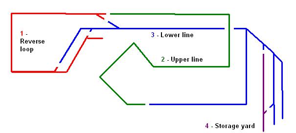
The ON-OFF-ON switches were wired up to control the sections. Flicking the switch to the right enables the right hand controller to power the section and vice versa. The ON-ON switch has been wired into the circuit for the reversing loop (track section A) to enable the polarity to be switched independently of the rest of the layout, thereby enabling reverse running over this section without short circuit.
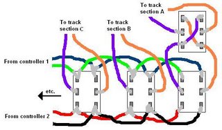
NOTE: ON-OFF-ON switches can be switched to one of three positions left, right or centre (off)(upright).
Points switches
The (ON)-OFF-(ON) points switches were wired up us reversing switches, with a 16v DC transformer (purchased for £1.00 from a swapmeet), providing the power source: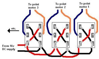
NOTE: (ON)-OFF-(ON) means that the switch biased to remain in the centre 'off' position. After switching either way it springs back to the centre off position. This makes it ideal for point switching as the point motor needs only a momentary pulse of electricity to operate.
Finishing off
Although the the result looks like a knitting basket, it does the job:
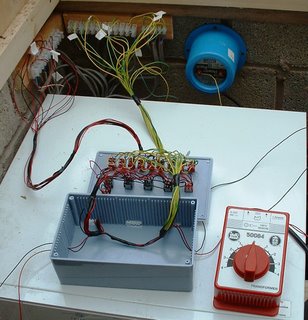
As can be seen from the above photo, the wires from the control panel are connected to the heavier weight wiring used in the garden via connection blocks. These are hidden beneath the work-surface to provide a reasonably tidy finish.
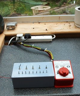
The control box has been tested and functions well. The finishing touch will be the addition of a second transformer/controller. These seem to come up on eBay regularly for quite reasonable prices. Though, as indicated above, until I have at least one more loco, a second controller is not needed.
Materials
A trip to my local electronics store (Maplin) provided me with the following:
1 x ABS project box (191mm x 110mm x 57mm) @ £3.79
5 x ON-OFF-ON DPDT subminiature toggle switches @ £1.94 ea
1 x ON-ON DPDT subminiature toggle switch @ £1.96
9 x (ON)-OFF-(ON) DPDT subminiature toggle switches @ £1.94 ea
Section switches
The ON-OFF-ON switches were wired up to control the sections. Flicking the switch to the right enables the right hand controller to power the section and vice versa. The ON-ON switch has been wired into the circuit for the reversing loop (track section A) to enable the polarity to be switched independently of the rest of the layout, thereby enabling reverse running over this section without short circuit.

NOTE: ON-OFF-ON switches can be switched to one of three positions left, right or centre (off)(upright).
Points switches
The (ON)-OFF-(ON) points switches were wired up us reversing switches, with a 16v DC transformer (purchased for £1.00 from a swapmeet), providing the power source:

NOTE: (ON)-OFF-(ON) means that the switch biased to remain in the centre 'off' position. After switching either way it springs back to the centre off position. This makes it ideal for point switching as the point motor needs only a momentary pulse of electricity to operate.
Finishing off
Although the the result looks like a knitting basket, it does the job:

As can be seen from the above photo, the wires from the control panel are connected to the heavier weight wiring used in the garden via connection blocks. These are hidden beneath the work-surface to provide a reasonably tidy finish.

The control box has been tested and functions well. The finishing touch will be the addition of a second transformer/controller. These seem to come up on eBay regularly for quite reasonable prices. Though, as indicated above, until I have at least one more loco, a second controller is not needed.