It has been quite an eventful summer - not least because the weather has been very changeable which is not good news for garden railway modelling. However, there have been a few developments since the last Progress Report (see Progress Report 60).

As the viaduct needed to be readily removable to allow access, I wanted something relatively lightweight but nonetheless reasonably realistic. I had already built structures using balsa wood to represent stonework (following ideas proposed by Peter and Kes Jones in Making Model Buildings for Garden Railways). And so a lightweight plywood substructure was made and clad in around 3500 individually cut, shaped, glued, grouted, textured and painted balsa wood blocks.


On a less ambitious scale, there had always been a slight drop at the end of the swing bridge at Bulkeley but I had begun to notice that the slope was becoming more severe. The trackbed at Bulkeley seemed to have dropped by around 5cm.

Previously, I had attacked the slot into which the end of the bridge fitted with a hammer and cold chisel, but this time I felt the time had come for more drastic action. The slot was deepened with an angle grinder.

The transition from bridge to terra firma is now a lot less abrupt - but as you can see, the ground level has shifted quite considerably over the past ten years.


What I hadn't appreciated was that the overall length of the siding would not accommodate the fifth ( Accucraft Welshpool & Llanfair) cattle wagon which the line acquired. Fortunately, there was sufficient space between the end of the siding and the adjacent tracks for it to be extended by 3cm. However, the track had been embedded in concrete and so I was unsure as to whether it would be possible to extend the siding without major engineering works. I decided that, if I could sever the track just before the rail built buffer stop, I might be able to insert a short length of track with the minimum of disruption.
The track was cut with a slitting disk attached to a mini drill and the buffer stop was prised out with a hammer and chisel. The 3cm length of track was inserted into the gap.

The siding is now just the right length to accommodate all five cattle trucks, with plenty of room for stock to pass by.


During the build, I had had a major problem with the layshaft. The only flycranks I could find (from Garden Railway Specialists - GRS), had 8mm offsets but the cranks on Tollemache's drivers had 10mm offsets. Although I solved the problem at the time by slotting the bearings in the connecting rods, I was never happy with the sloppy motion which this produced. I felt I needed to find a better way of solving the problem before I set about making the conversion to battery power. It turned out that the solution was a lot more straightforward than I had anticipated (see How I increased the offset on my GRS whitemetal flycranks)

Once this problem had been sorted out, the installation of the three 18650 li-ion batteries, protection board, switch, charge socket and the Deltang Rx65a receiver/controller was very straightforward (see How I converted my Fowler diesel to battery radio control).

She has now assumed duties and has already participated in a couple of test runs. I can't wait for some decent weather so she can once more take part in a full operating session. As you can see, I am now more than happy to video her running slowly.

As indicated above, Fowler Loco No, 7 (Tollemache) has now been converted from track power to battery power using the Deltang Rx60a receiver which was removed from Manning Wardle Loco No. 6 (Harthill).

I had re-bound this loco from my Tx22 transmitter to my Tx21 transmitter but was finding that the Tx22-enabled Rx65a was struggling to remain bound to the Tx21. Rather than re-program the Rx60a, I decided to buy another Rx65b which was already programmed for use with Tx21 (or Tx20) - an Rx65-2.
When I constructed an IP Engineering 'Jessie' kit which became loco No. 8 (Wynford), the only suitable Deltang receivers which were available could handle only 1.5amps.

Wynford sometimes drew more amps than this and so was unreliable with the lower power receivers. To solve the problem I installed a Deltang Rx102 receiver linked to a Brian Jones Mac5 ESC. Since the release of the Deltang Rx65, I have been meaning to install one in Wynford but, as she was functioning happily, I felt there was no urgency. An enquiry on the 16mm NGM forum from a fellow modeller, asking which Deltang Rx would be most suitable for an IP Engineering 'Jessie' with a soundcard, prompted me to replace the Rx102/Mac5 arrangement with an Rx65, to ensure my suggestion was appropriate. The Rx65 needed to be re-programmed to allow the DigiSounds soundcard to be controlled from the transmitter and Wynford is now happily re-energised and back in service (see How I installed an Rx65 in my IP Engineering 'Jessie').
Manning Wardle Loco No. 4 (Bulkeley) has now had her Deltang Rx60 receiver replaced with an Rx65. Although Bulkeley was working satisfactorily, I have decided that I want to standardise the receivers in my locos and the Rx65 includes features which one day I might want to exploit (eg auto-station stop).

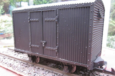
Similarly, the Accucraft Lynton & Barnstaple van which I had bought a few years ago was now surplus to requirements. The other vans on the line (converted from LGB vans) are larger and hence L&B van looked out of place. It too followed the corrugated van.

Apart from some ongoing maintenance (mainly re-fixing couplings) there have been no further developments with rolling stock since the previous Progress Report.
Having constructed a second rake of coaches (see How I converted Bachmann Jackson Sharps into Leek & Manifold coaches), I felt it was about time I ran two passenger trains at the same time (assuming it was a busy market day during the summer season). Here we see Sharp Stewart Loco No. 5 (Tarporley) on an Up passenger .........

...... crossing Manning Wardle Loco No 6 (Harthill) at Bulkeley on a Down passenger service.

During another operating session, a few photos were taken of trains in action ....
In addition, the railway hosted a visitor, Derek, who brought two locos with him - a Peckett and a Hunslet built from GRS kits
Autumn is upon us. As you can see from the above photo, the apple tree is starting to shed its leaves and there is a definite nip in the air. My railway todo list seems as long as ever and so, over the winter season, I hope to clear some items off it, such as:

- In terms of infrastructure, the major development has been the completion (after two years) of the viaduct crossing the access to the patio. In addition, the unintended incline at the end of the swing bridge on the approach to Bulkeley station has been iron-out.
- Very little has happened with the permanent way, though the siding for the cattle dock at Beeston Market has been extended a little.
- A very pleasing development has occurred in the motive power department - the last remaining track-powered locomotive (Fowler No.7 - Tollemache) has been converted to battery power
- There have been several developments in Controls - some of the Deltang receiver/controllers have been updated in the locos and a new Tx20 Deltang transmitter has been constructed to now give three separate controllers for locomotives
- Some of the little-used rolling stock has been passed on to other railway companies and there have been a number of general repairs to serving rolling stock
- Operating sessions have been sporadic - partly owing to the unpredictable weather, partly because we have been away on holiday and partly because other developments have taken priority. However, I have managed a couple of full operating sessions and played host to fellow modeller.
Infrastructure
Two years ago, I decided to replace the rather ramshackle structure which pretended to be a viaduct across the access path to the patio. This had become an experimental test-bed for construction techniques with the plywood base being covered at various times with a range of claddings such as tile cement, plaster of Paris, grout and filler. The intention was to indent and/or scribe these materials to represent stone blockwork. None had proved particularly successful and the plywood was beginning to rot.
As the viaduct needed to be readily removable to allow access, I wanted something relatively lightweight but nonetheless reasonably realistic. I had already built structures using balsa wood to represent stonework (following ideas proposed by Peter and Kes Jones in Making Model Buildings for Garden Railways). And so a lightweight plywood substructure was made and clad in around 3500 individually cut, shaped, glued, grouted, textured and painted balsa wood blocks.


On a less ambitious scale, there had always been a slight drop at the end of the swing bridge at Bulkeley but I had begun to notice that the slope was becoming more severe. The trackbed at Bulkeley seemed to have dropped by around 5cm.

Previously, I had attacked the slot into which the end of the bridge fitted with a hammer and cold chisel, but this time I felt the time had come for more drastic action. The slot was deepened with an angle grinder.

The transition from bridge to terra firma is now a lot less abrupt - but as you can see, the ground level has shifted quite considerably over the past ten years.

Permanent Way
Apart from the usual ongoing maintenance of keeping the stock moving and the wheels on the track, there have been no major developments on the permanent way since the last progress report. The most significant development has then the extension of the siding serving the cattle dock at Beeston Market. When I built the cattle dock (see How I constructed a cattle dock), I was more concerned with ensuring that the dimensions of the gates and railings matched the positions of the doors on the four cattle wagons which the line possessed at that time.What I hadn't appreciated was that the overall length of the siding would not accommodate the fifth ( Accucraft Welshpool & Llanfair) cattle wagon which the line acquired. Fortunately, there was sufficient space between the end of the siding and the adjacent tracks for it to be extended by 3cm. However, the track had been embedded in concrete and so I was unsure as to whether it would be possible to extend the siding without major engineering works. I decided that, if I could sever the track just before the rail built buffer stop, I might be able to insert a short length of track with the minimum of disruption.
The track was cut with a slitting disk attached to a mini drill and the buffer stop was prised out with a hammer and chisel. The 3cm length of track was inserted into the gap.

The siding is now just the right length to accommodate all five cattle trucks, with plenty of room for stock to pass by.


Motive Power
The biggest development here has been the conversion of my last track powered locomotive to battery power. The Fowler(ish) Loco No. 7, Tollemache, was the first loco I scratchbuilt and so has particular poignancy for me (see How I constructed an early Fowler diesel locomotive).During the build, I had had a major problem with the layshaft. The only flycranks I could find (from Garden Railway Specialists - GRS), had 8mm offsets but the cranks on Tollemache's drivers had 10mm offsets. Although I solved the problem at the time by slotting the bearings in the connecting rods, I was never happy with the sloppy motion which this produced. I felt I needed to find a better way of solving the problem before I set about making the conversion to battery power. It turned out that the solution was a lot more straightforward than I had anticipated (see How I increased the offset on my GRS whitemetal flycranks)

Once this problem had been sorted out, the installation of the three 18650 li-ion batteries, protection board, switch, charge socket and the Deltang Rx65a receiver/controller was very straightforward (see How I converted my Fowler diesel to battery radio control).

She has now assumed duties and has already participated in a couple of test runs. I can't wait for some decent weather so she can once more take part in a full operating session. As you can see, I am now more than happy to video her running slowly.
Controls
There have been a few developments in the area of control technology on the railway. The most significant is the construction of a new Deltang transmitter, a Tx20 (see How I constructed a Deltang Tx20 transmitter).As indicated above, Fowler Loco No, 7 (Tollemache) has now been converted from track power to battery power using the Deltang Rx60a receiver which was removed from Manning Wardle Loco No. 6 (Harthill).

I had re-bound this loco from my Tx22 transmitter to my Tx21 transmitter but was finding that the Tx22-enabled Rx65a was struggling to remain bound to the Tx21. Rather than re-program the Rx60a, I decided to buy another Rx65b which was already programmed for use with Tx21 (or Tx20) - an Rx65-2.
When I constructed an IP Engineering 'Jessie' kit which became loco No. 8 (Wynford), the only suitable Deltang receivers which were available could handle only 1.5amps.
Wynford sometimes drew more amps than this and so was unreliable with the lower power receivers. To solve the problem I installed a Deltang Rx102 receiver linked to a Brian Jones Mac5 ESC. Since the release of the Deltang Rx65, I have been meaning to install one in Wynford but, as she was functioning happily, I felt there was no urgency. An enquiry on the 16mm NGM forum from a fellow modeller, asking which Deltang Rx would be most suitable for an IP Engineering 'Jessie' with a soundcard, prompted me to replace the Rx102/Mac5 arrangement with an Rx65, to ensure my suggestion was appropriate. The Rx65 needed to be re-programmed to allow the DigiSounds soundcard to be controlled from the transmitter and Wynford is now happily re-energised and back in service (see How I installed an Rx65 in my IP Engineering 'Jessie').
Manning Wardle Loco No. 4 (Bulkeley) has now had her Deltang Rx60 receiver replaced with an Rx65. Although Bulkeley was working satisfactorily, I have decided that I want to standardise the receivers in my locos and the Rx65 includes features which one day I might want to exploit (eg auto-station stop).

Rolling Stock
Because I have recently constructed a new gunpowder van (see How I constructed a gunpowder van), the Swift Sixteen corrugated van which had been pressed into service as an explosives van was now redundant and so was sold to a fellow modeller through eBay.
Similarly, the Accucraft Lynton & Barnstaple van which I had bought a few years ago was now surplus to requirements. The other vans on the line (converted from LGB vans) are larger and hence L&B van looked out of place. It too followed the corrugated van.

Apart from some ongoing maintenance (mainly re-fixing couplings) there have been no further developments with rolling stock since the previous Progress Report.
Operations
I have had the opportunity for a few operating sessions since the last report in July, though these have been less frequent than I would have liked as holidays, the weather and projects (such as the viaduct) have taken up time that might have been used for running trains. However, a couple of full operating sessions have been squeezed in and from time to time I have run a train or two for an hour or so.Having constructed a second rake of coaches (see How I converted Bachmann Jackson Sharps into Leek & Manifold coaches), I felt it was about time I ran two passenger trains at the same time (assuming it was a busy market day during the summer season). Here we see Sharp Stewart Loco No. 5 (Tarporley) on an Up passenger .........

...... crossing Manning Wardle Loco No 6 (Harthill) at Bulkeley on a Down passenger service.

During another operating session, a few photos were taken of trains in action ....
 |
| Barclay Loco No. 2 Beeston about to depart Beeston Market |
 |
| Freelance diesel, Wynford, passing the engine shed at Beeston Market |
 |
| No. 2 (Beeston) passing an Up ore train at Bulkeley |
 |
| Peckett Loco No. 1 on a Down pickup goods passing an Up ore train at Beeston Castle |
 |
| No. 1 on an Up goods approaching Bulkeley while No. 2 approaches Beeston Castle on a Down passenger |
 |
| Derek's Peckett leaving Peckforton, crossing the viaduct |
 |
| Approaching Bulkeley on Gallantry Bank |
 |
| Peckett and Hunslet (Linda) storming up Gallantry Bank |
 |
| Double header approaching Bulkeley |
- installing interiors and lighting in the Leek & Manifold coaches
- installing solar lighting at the stations
- adding more detail to goods wagons
- exploring auto station stop for locos equipped with Rx65b receivers
- constructing a couple of horse drawn wagons
- constructing buildings for the approach to Beeston Market station
- etc etc etc


