Showing posts with label Picaxe. Show all posts

Sunday, February 21, 2016

How I used Picaxe to operate semaphore signals by remote control

The signals

I constructed nineteen lower quadrant signals to control train movements in and out of the five stations on my railway. The signals were scratchbuilt using a variety of materials - wood, brass, copper and plastic (See How I constructed some semaphore signals).

Once I had constructed them, the next issue was how to control them. I considered mechanical control, using a ground frame and cables but, because of their fragility, I wanted something which would easily enable me to remove the signals when the railway was not in use. An electro-mechanical system seemed to me to be the most appropriate approach. The next question was - 'How?'

The electronics

My first priority was cost. As I had nineteen signals, I wanted a system which was not going to break the bank (particularly as I am now living off a pension). I hunted around (mostly eBay) for a cost effective radio control system which might meet my needs and came across these keyfob r/c systems which can control up to four outputs. As my stations each required no more than four signals, this seemed like the ideal solution - and what is more they cost under £5.00 for the complete system of receiver and transmitter. Five sets were ordered from China.
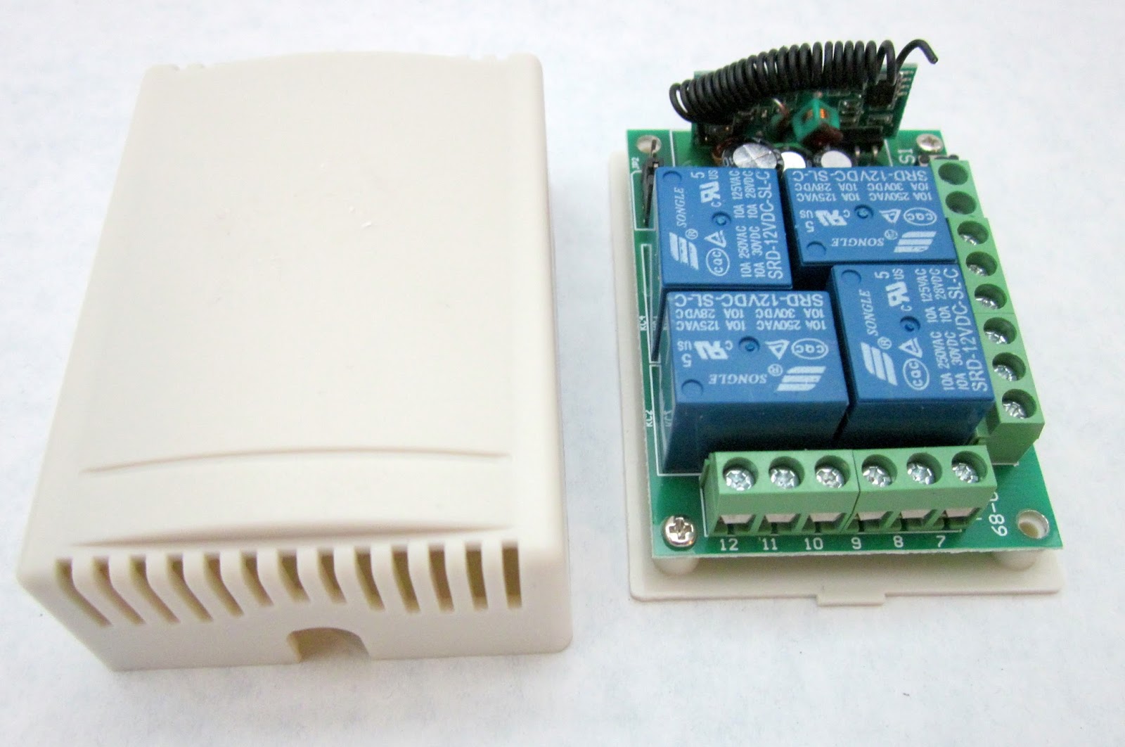


Having sorted out the radio control aspect, the next problem was to figure out how to turn the output from the receiver into something that could operate servos. Fortunately, my modelling mate in Australia is very familiar with using Picaxe processors to interpret radio control signals and turn them into something useful for garden railway. Greg Hunter has a highly informative and accessible website on which he shares his expertise - http://www.trainweb.org/SaTR/Picaxe%20tutes.htm . A few email conversations later and I had the necessary information for interfacing the output from the r/c receiver with a Picaxe 14 Project board.
 In fact, the wiring was relatively straightforward. Basically, four pairs of (blue) wires were connected from the remote control receiver to provide inputs to the Picaxe board, and four (white) wires were connected from the outputs of the Picaxe board to the servos. The only complication was that the receiver required 12 volts, and the Picaxe project board and servos required 4.5 volts and so a voltage regulator was mounted on to a separate piece of circuit board to turn the 12 volts supply into 4.5 volts. The circuit board to the left of the picture is a distribution board for the servos and the signal lamp LEDs - providing them with power.

The program

Greg proved very helpful in devising the bounce procedure for the program and advising on the coding for triggering the actions. The program for the Picaxe board interprets the signals from the remote control receiver to determine which button had been pressed on the handset. It also remembers the position of each of the four signals and so subsequent presses of the button on the transmitter will change the signal from on to off and vice versa.

Outline of the procedures in the program

Init procedure
This ensures that all the signals are put into the 'on' position (ie set to danger) when the program is initiated

Starter
This checks the state of the outputs from the receiver and compares that with the stored position of each signal arm. If it receives a signal from the receiver, it then goes to the relevant sub procedure to raise or lower the signal arm.

Raiseit
As implied, this procedure raises the signal arm, calling the first and second bounce procedures to simulate the effect of the bouncing signal arm

Lowerit
As above, but lowers the signal arm

(Note: Explanatory comments in blue)

'FOUR semaphore signal driven by servos with bounce
'bounce2semaphore v1.bas tested 10/6/14 364 bytes
'assumes a constant acceleration going to STOP,
'constant speed going to clear (down)
'controls 4 signals. Same bounce routine used for each
'raising bounce equations are:
'for initial rise: R=160t*t-50 degs for t<0.56s
'1st bounce down and up: R=87(t-1.04)^2-20 degs for 0.56<t<1.52s
'2nd bounce down and up: R=68(t-1.84)^2-7 degs for 1.52<t<2.16
'this is for Clockwise rotation direction to raise arm to STOP

'constants for raising
symbol lowered=170 '10us counts NB coincidence of equation coeff of t squared!
symbol raised=110 'counts
symbol initcoeff=160 'coeff of t squared in equation for counts =50/0.56^2
symbol bounce1coeff=87
symbol mincounts1=132 'min counts of first bounce (raised+20)
symbol bounce2coeff=68
symbol mincounts2=118 'min counts of 2nd bounce (raised+7)

'constants for lowering:
symbol bouncelow= 176 'counts for 72deg
symbol bouncelowup=158 'counts for 40deg

'variables:
symbol sig1state=b0 '0=clear(down), 1=stop(up)
symbol sig2state=b1
symbol sig3state=b9
symbol sig4state=b10
symbol t=w1 'time in ms
symbol t1=w2 'intermediate value in eqns
symbol S=b6 'location of servo in 10us counts
symbol k=b7 'loop counter
symbol sigpin=b8 'the pin number for that signal(1 to 4)
'--------------------------------------
init:
pulsout B.1, raised
sig1state=1
pause 20
pulsout B.2, raised
sig2state=1
pause 20
pulsout B.3, raised
sig3state=1
pause 20
pulsout B.4, raised
sig4state=1
pause 20

starter:
'check inputs and refresh servo pulses
'signal 1
sigpin=1
if pinC.1=1 and sig1state=0 then 'need to go to stop/raised arm
S=raised 'initial setting for raiseit subroutine
gosub raiseit
sig1state=1
pause 20
elseif pinC.1=1 and sig1state=1 then 'need to lower it to clear
S=lowered
gosub lowerit
sig1state=0
pause 20
endif

'signal 2
sigpin=2
if pinC.2=1 and sig2state=0 then
S=raised
gosub raiseit
sig2state=1
pause 20
elseif pinC.2=1 and sig2state=1 then
S=lowered
gosub lowerit
sig2state=0
pause 20
endif

'signal 3
sigpin=3
if pinC.3=1 and sig3state=0 then
S=raised
gosub raiseit
sig3state=1
pause 20
elseif pinC.3=1 and sig3state=1 then
S=lowered
gosub lowerit
sig3state=0
pause 20
endif

'signal 4
sigpin=4
if pinC.4=1 and sig4state=0 then
S=raised
gosub raiseit
sig4state=1
pause 20
endif
if pinC.4=1 and sig4state=1 then
S=lowered
gosub lowerit
sig4state=0
pause 20
endif

goto starter

raiseit:
'for initial rise: R=initcoefft*t-initdegs in degs with t in sec
'so R=initcoeff/1000000 *t*t-initdegs degs for t in ms
'to convert to counts,
' R=initcoef/1000000*t*t-lowered
if S<raised then firstbounce
t=t+25 'add 25 ms but pause later is less than this to make it go faster
S=t/10*initcoeff/100*t/1000
S=lowered-S
pulsout sigpin,S
pause 17
goto raiseit

firstbounce:
'S=-bounce1coeff x (t-1.04)^2 + mincounts1

S=raised
FB2:
if S<raised then secondbounce
t=t+25
if t<1050 then
t1=1050-t
else
t1=t-1050
endif

t1=t1/5*t1/100 'square it
t1=t1*bounce1coeff/2000 'intermediate num
S=mincounts1-t1
pulsout sigpin,S
pause 16
goto FB2 'firstbounce

secondbounce:
'S=-bounce2coeff x (t-1.84)^2 + mincounts2
if t>2140 then finished
t=t+25
if t<1850 then
t1=1850-t
else
t1=t-1850
endif

t1=t1/4*t1/50 'square it
t1=t1*bounce2coeff/5000
S=mincounts2-t1
pulsout sigpin,S
pause 15
goto secondbounce

finished:
t=0
pause 20
return
'+++++++++++++++++++++++++++++++++++++++++++++++++++++++++++++++++
'lowering linearly

'takes 580ms to go from horiz to -55 deg, bounces up to -40 deg in 380ms
'then drops to -50 deg in 380ms, and stops there. total 1340ms

'these just a copy of actual declarations at top, for ease of reference....
'symbol bouncelow=176 'counts for 55deg
'symbol bouncelowup=158 'counts for 40deg
'symbol lowered=170 'counts for 50deg
'symbpl raised=110 'counts for horizontal 0 deg

lowerit:

for k=raised to bouncelow step 3 '66/3 counts in 580ms gives 26 ms/count
pulsout sigpin,k
pause 20
next k

'pause 100 (Might be needed)

for k=bouncelow to bouncelowup step-1 '18 counts in 380ms gives 21 ms/count
pulsout sigpin,k
pause 18
next k
'pause 100

for k= bouncelowup to lowered '12 counts in 380ms gives 31ms/count
pulsout sigpin,k
pause 27
next k

pause 20
return

Installation


Small servos were mounted at the base of each signal, with a bell crank linking the servo arm to the signal operating wire.

The receiver board, the Picaxe board, the voltage regulator board, an auto reset fuse (1.6A) and an on/off switch were mounted in an airtight container.

 Power was provided by a 12v lead-acid battery designed for use with burglar alarm systems.

 The battery and the encased electronics were housed on a purpose-built ledge beneath the baseboard ......

 .... and the control leads and the power supply cables for each of the signals  were connected through two three-way plugs and sockets to the distribution cables for each signal.

Suitable resistors for the 4.5v supply to the signals were soldered to the LEDs in the signal lamps .....

..... and holes were drilled into the baseboard at Beeston Market station to accommodate the servos beneath each signal.

The signals were then connected to the underboard wiring with servo plugs.

...... and I was pleased to find the signal LEDs actually worked.

 The whole system was then given a thorough testing .......

 Conclusion

 One of the delights I have in garden railway modelling is the opportunity it affords for pushing the boundaries and learning something new. With my interest in IT and ICT, I had dabbled with control programming in an educational setting for quite a few years but this project enabled me to explore a new area - programming PIC chips and applying this knowledge to the solution of a real problem. There is no better way to learn something new than to develop new knowledge and skills for a purpose. Book learning has its place, but for real learning - there is nothing like the application of knowledge to experience!

I still have to solve the problem of how to deploy the signals at the four other stations around the railway. These are all at ground level and so it will be difficult to put the servos beneath each signal. The will probably be sited at the base of each signal above ground level. Although this may make the signals appear slightly less realistic, I think it's a small price to pay for having them operational.

Although very few narrow gauge railways in the UK used signalling (eg the Southwold, the Isle of Man and the Ffestiniog), I feel that seeing white signal posts and red signal arms in the garden setting adds a certain something to the attractiveness of the a garden railway. Even better if the signals are illuminated and animated!

Sunday, August 23, 2015

How I operate some of my points by remote control using Deltang equipment

The Rationale

When I set up my railway, I naively thought I would be able to operate it from one central position and so made a control panel which was situated in the corner of the leanto. In those early days, my locomotives were all track-powered and controlled by a couple of small LGB transformer controllers.

The trackplan was separated into five electrically isolated sections (switches A - E) and all nine points were operated by point motors using two-way centre-biased switches. There was also a reverse loop operated by a reversing switch.

However, I quickly realised that, not only was following trains around essential when running them in the garden, it was a lot more enjoyable. And so, I invested in various remote control systems using track power, culminating in DCC (see Digital Developments). I was quite satisfied with DCC for several years as it simplified the wiring around the garden (no need for isolated track sections) and I could operate the remote controlled points from the DCC handset. As the wiring to the point motors was already in situ, I placed the the points decoders (and the reverse loop controller) inside the now redundant control panel. This helped protect them from the elements.

Over the past three years, I have steadily experimented-with and ultimately adopted radio control and battery power. I was fed-up with constantly cleaning the track, tracing faulty electrical track joints and having locos grind to a halt when shunting or slow running. My biggest regret, though, was losing the ability to control my awkward-to-reach pointwork remotely from the DCC handset.

On my layout there are six turnouts which are difficult to access, marked in red on this trackplan.


Having sold off my DCC equipment, I ran the railway for a while by operating these points manually. Whilst this was possible, it was quite inconvenient. Most of these points needed to be changed repeatedly during an operating session and bending, reaching and stretching is something which is becoming increasingly difficult as I dodder into old age.

Having become of fan of Deltang radio control equipment for my locos, I was intrigued when David T (Mr Deltang) developed and produced a remote points controller using his 2.4gHz radio control system. It works by controlling servos which can be used to switch the blades of turnouts.

I considered replacing my existing LGB point motors with servos but the logistics of making the transition seemed daunting. For one thing, each servo would need three wires whereas the LGB point motors only require two. This would have entailed running additional wiring around the garden. Also, I was not certain how much the signal wire to each servo would be affected by the long run of wiring from the control box in the leanto to each turnout. The more I thought about it, the more unfeasible it became. "It's a pity the r/c unit couldn't be configured to operate LGB point motors," thought I.

I am in regular correspondence with a fellow garden railway modelling in Australia. Greg Hunter, whose Sandstone & Termite Railway has many similarities with mine, is a dab hand at anything electronic and has produced a series of online articles about using programming Picaxe micro-chips for controlling locos and lineside features. When I explained the situation he immediately concluded that, providing the Deltang receiver could provide binary on/off outputs rather than only servo signals, it would be feasible. The Rx105 receiver used with the unit comes in various configurations (including on/off 'lighting' outputs) and can be re-programmed by the user to provide any combination of outputs - and so  the project looked distinctly doable.

The Transmitter

I sent off for the kit version of the Deltang Tx27 and the Rx105 receiver, which duly arrived (only £22 at the time of writing).

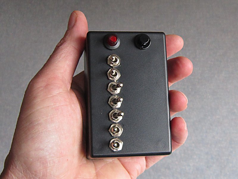
The most difficult stage of making the kit was to drill the holes in the ABS box. I marked these out in a pattern which would loosely represent the relative position of the pointwork on my layout, and drilled the 6mm diameter holes needed for the switches.

The switches were then inserted into the holes and the nuts tightened.

The connections were then wired to the relevant pins on the receiver, following the circuit diagram provided with the kit.

Once all the wiring had been completed, a PP3 battery was connected and the transmitter powered up. There was no way of testing it at that moment, but it seemed to be functioning as expected.

The switching system


The process

  1. When a switch (eg switch 2) is clicked on the the transmitter, a signal is sent to the receiver.
  2. The receiver sends a signal to the Picaxe board (eg input 2)
  3. On receipt of the signal, the Picaxe board checks which way the relevant point (eg Point 2) is already pointing. 
  4. If the point needs reversing, the Picaxe board triggers the reversing relay on the relay board and then triggers the relevant relay (eg Relay 2) to send a 12v pulse to the point motor.

The Relay board

I next turned my attention to constructing the relay board needed to operate the point motors. With Greg's help, we had worked out that we needed six double pole on/off (DPST) relays to operate the six turnouts and a double-pole, double-throw (DPDT) relay to act as a reversing switch to send the point motor one way or the other. Hopefully, this circuit diagram helps explain the relay board's contribution to the system:


The six two pole on-off relays were soldered to a piece of Veroboard in two rows of three, and the DPDT relay beside them.

I tried to ensure that the terminals for the common connections on the relays (such as ground) were soldered to the same rails of the board.

The relays were then wired up - blue wires providing the 12v output to the point motors, the white wires receiving the 5v energising pulses for the relays from the Picaxe board.


The Picaxe-18 Project board was then wired up. The white wires from the point actuating relays were attached to outputs 0-5, and the reversing relay wire was attached to output 7. The white (signal) leads from six servo plugs were attached to inputs 0-2 and 5-7 (3 and 4 are not used for switched inputs) and a 5v voltage regulator with smoothing capacitors was mounted on another piece of Veroboard and connected to the Picaxe board using the 12v supply from an old Scalextric transformer. This also supplies the current needed to switch the point motors.

The 12v supply was then connected to the point actuating relays (the purple wire).

A test program was uploaded to the Picaxe board to check that our logic was correct and the circuitry was given a test run with a spare point motor connected in turn to each of the relay outputs.

The Picaxe was then loaded with the full program and tested, before the assembly was connected to the wiring for the point motors and placed in the control box.

The Picaxe Program

The program for the Picaxe controller uses two main procedures - one to check the initial state of the switches on the transmitter when powered up - and the main, continuously looping procedure which keeps checking for a change in the position of any of the switches on the transmitter.

On power-up the Picaxe checks the existing state of outputs from the receiver and switches each of the relays (and hence the point motors in turn). This ensures that whichever way the switches are pointing on the transmitter, matches the way the points are switched.


Here is the initial checking procedure:

'Program for relay control of point motors using Deltang Tx27 and Rx105-7

'Pin allocation
'pinC.0 input1
'pinC.1 input2
'pinC.2 input3
'pins C.3 and C.4 cannot be used as inputs
'pinC.5 input4
'pinC.6 input5
'pinC.7 input6
'pinB.0 output1
'pinB.1 output2
'pinB.2 output3
'pinB.3 output4
'pinB.4 output5
'pinB.5 output6
'pinB.7 DPDT relay

'ASSUME when input transition is low to high, switch left
'and when input high to low transistion, switch right
'Variables
symbol oldinput1=b6
symbol oldinput2=b7
symbol oldinput3=b8
symbol oldinput4=b9
symbol oldinput5=b10
symbol oldinput6=b11 'the last read state of the input pins

'++++++++++++++++++++++++++++++++++++++++++++++++++++++++++++++++++
'This is to set the turnout to the input conditions of the receiver at turnon.
initialize:
'if it's a low input at turn on, switch right.
'if it's high, switch left.

if pinC.0 = 1 then  'checks the input to see if it is high and if so .....
oldinput1 = 1         'stores the state of the switch for future reference
high B.7                 'energises the reversing relay
pause 100
high B.0                 'energises the points relay 1
pause 500               'for half a second
low B.0                  'then turns the relay off
pause 100
low B.7                  'and turns the reversing relay off
else                        'otherwise .....
oldinput1 = 0         'stores the state of the switch
low B.7                  'makes sure the reversing relay is off
pause 100              
high B.0                 'switches on the relay for point 1
pause 500               'for half a second
low B.0                  'then switches it off
endif
.
.
'This procedure is now repeated for each of the inputs and outputs with similar blocks of code
Once the checking procedure has completed, the main procedure is executed. This continually checks the state of the inputs from the receiver (and hence the transmitter) and if it detects a change, it instructs the relevant relay to send a pulse of 12v to the point motor.
start:
'1st relay
if pinC.0 = 1 and oldinput1 = 0 then    'checks if the switch on the tx has moved, if so ...
oldinput1 = 1 'stores the new position of the switch
high B.7                                              'switches on the reversing relay

pause 100                                            'for a second
high B.0                                              'switches on the relay for point 1
pause 500                                            'for half a second
low B.0                                                'switches off relay 1
pause 100
low B.7                                                'switches off the reversing relay
elseif pinC.0 = 0 and oldinput1 = 1 then 'checks if the tx switch is the other way
 oldinput1 = 0
low B.7
pause 100
high B.0
pause 500
low B.0 endif
.
.
'The above block of code is replicated for each of the remaining sets of inputs and outputs.
.

.
goto start
'=======================

And that's basically all there is to it .......


Two of the outputs switch two point motors - the crossover at the back of the garden and the mine link. I have now also fitted a Capacitor Discharge Unit into the 12v supply for the point actuating relays to ensure these motors get the extra kick needed. It wasn't essential, they were switching successfully, but I happened to have a spare left over from my indoor 00 layout.


Saturday, January 10, 2015

Progress Report 56

Now we are entering the winter season, there are fewer opportunities to run trains, but supposedly more opportunities for finishing off construction projects. So far, it has turned out to be more difficult than expected to find time for construction and so progress has been limited. However, there are several projects now on the agenda which I can report on.

Acquisitions

Christmas has come and gone and left me with a couple of additions to the stocklist.

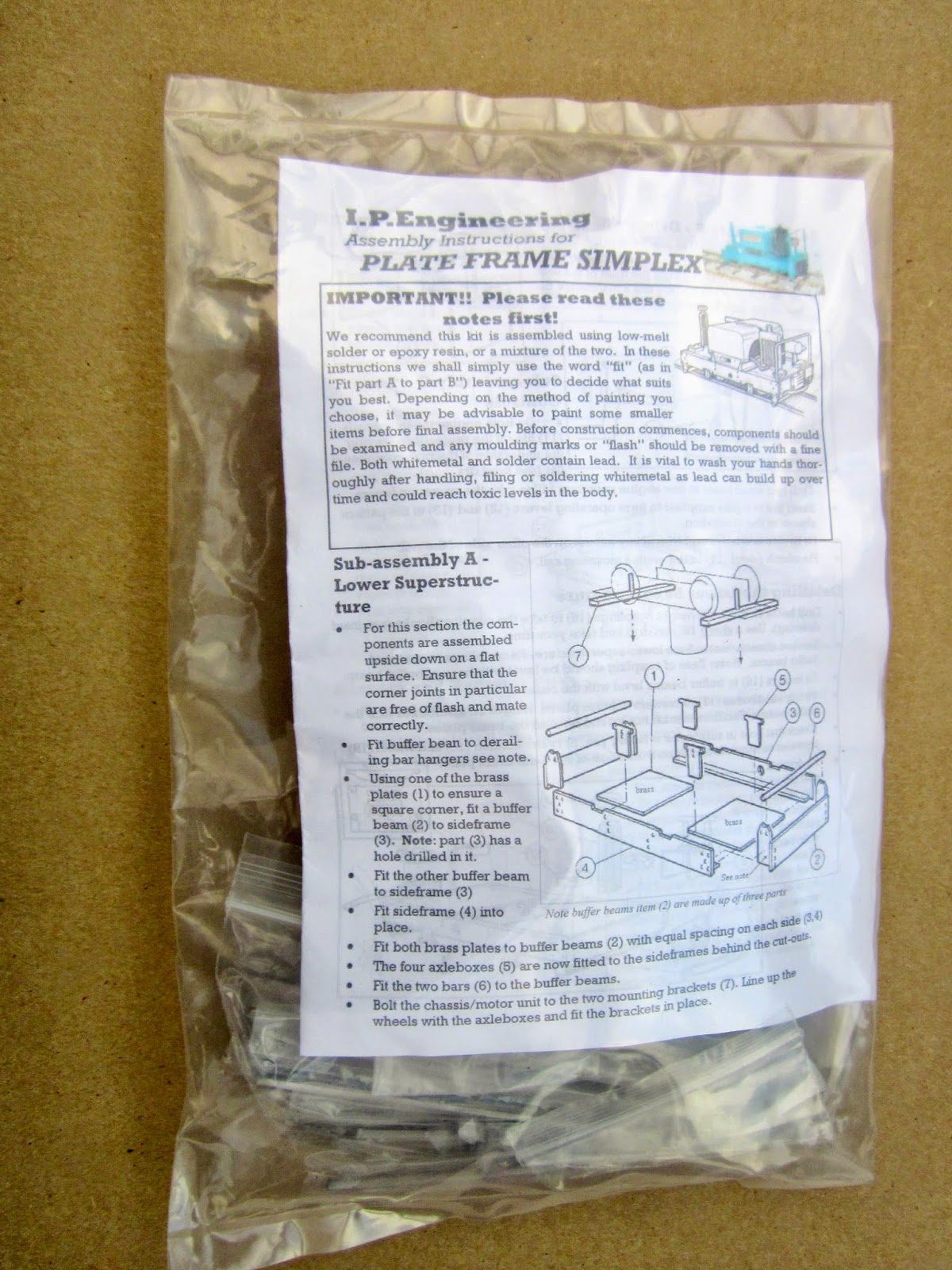
IP Engineering Simplex kit

I have been considering for a while making the feeder from the copper mine to the crushers and loading hopper into a 32mm (2') narrow gauge line (see Progress Report 45). At present it is 16.5mm gauge supposedly representing a 15" gauge railway (but nearer to 13") (see How I constructed some Gn15 skips) and as such it will only ever be cosmetic.

 My thinking was that by having a short stretch of 32mm track, I would have some stock which I could run when I visit other people's garden railways. I am also considering building a simple shuttle control system using a Picaxe micro controller. In the meantime, I now have an IP Engineering Simplex locomotive kit sitting in my 'pending' project box awaiting its turn on the to do list.

Guards' / baggage van

  I saw this on a well known online auction website and considered that the price was sufficiently attractive for it to become an addition to the line. At present, I do not have a dedicated guards' van which could be included in passenger trains and thought this might add more operational interest.

 The van itself has been constructed fairly crudely from plywood and mounted on an LGB chassis. This makes it quite heavy when compared to similar stock. The mouldings are mot particularly crisp and the paintwork is far from smooth. I think it will need some remedial work after being rubbed down in preparation for a repaint.
Also, it is taller than the existing rolling stock and I may consider lowering it on its chassis somehow. This is not a high priority on the todo list and so may languish on the shelves for a while before I decide to deal with it.

Nameplates

I've recently taken delivery of another two etched nameplates from Narrow Planet - my preferred supplier. The former Southwold Railway Sharp Stewart 2-4-2T (see How I constructed a Sharp Stewart 2-4-2T) will become Tarporley and the most recently completed former Davington Light Railway Manning Wardle 0-6-0 will become Harthill (see How I constructed a Manning wardle 0-6-0T). I am following the tradition set by the Southwold Railway of naming locomotives after villages and towns served by the railway.

Also included in the order were some works plates. Two sets of Manning Wardle plates for the former Southwold and Davington LR locos and a set of Sharp Stewart plates for Tarporley.

Jackson Sharp coach bashes

I am making slow but steady progress with these builds. One Open coach has been more or less completed, apart from interior detailing, while the modifications to the underframes and body shells for the remaining Open and the Brake are largely done. 
Open Coach based loosely on the Leek & Manifold coaches
 I still need to complete the roofs, windows, lights, underframe detailing and balconies for these two coaches but, by comparison with the work needed to modify the bodywork, progress should now be a lot swifter.
Progress so far on the Brake End L&M inspired coach
 After reading through some postings on the 16mm NGM forum, I have decided to experiment with printing the stained glass window detailing for the opening lights on to self adhesive acrylic sheet from Crafty Computer Papers.

Deltang radio control equipment upgrades

Since the last update I have constructed a new Tx21 transmitter from a kit and taken delivery of two Rx65b receiver/controllers from Deltang.

I decided to invest in a Tx21 so that when I have visitors there's another controller so we can run trains independently. This was certainly an asset when my Australian friend visited in October (see Progress Report 55).

I was pleasantly surprised at how easy it was to construct the transmitter. The main circuit board was included as a completed unit and all that was required was to drill holes in the case, mount the switches and potentiometer and then solder a few wires from the transmitter chip to the various switches. A few resistors needed to be included in some of the connections but these were relatively easy to solder into place. I'd say the drilling was the most difficult aspect of the build - ensuring the holes were in the right places and correct size.

Over the past couple of years, I have accumulated a range of Deltang receiver/controllers as and when they became available. Some of the early receiver/ESCs were rated only at 1amp which proved to be quite adequate for the LGB motor blocks I was using - but now that the Rx65 3amp receiver/controller has become available, I have decided to standardise.

My most recent loco, the Manning Wardle 0-6-0 has been equipped with one of these receivers and I have been very impressed with its performance. (see Manning Wardle load test video). It seems to be far more responsive and consistent in its smooth running, Whether the Piko 0-6-0 mechanism is responsible or whether the output from the receiver is the major contributory factor remains to be seen - but I will keep readers posted as to progress once the receivers have been installed.

Sound cards

My Australian friend, Greg, came bearing gifts, among which included a few 20 second sound recording chips.

Previously, I have been accumulating the necessary electronic bits and pieces needed to construct my own sound card using a Picaxe chip and a small amplifier. I am intending to follow the guidance given by my Ozzie visitor on his railway's website - http://www.trainweb.org/SaTR/Picaxe%20tutes.htm.

I have also invested in a small sound recording chip similar to those used in greetings cards.

 I am hoping that this will prove small enough to fit inside the Lollypop railcar (see How I Constructed an IP Engineering Railcar)

I still have four locomotives without sound (two steam and two internal combustion) and so, during the coming Spring I intend to construct my own sound systems using a combination of these components. Watch this space for more details.

Track cleaning

One of the great joys I have now is being able to run trains with the minimum of track cleaning and maintenance, compared with that required for operating track-powered locomotives. Recently, after a few weeks with no trains, I decided to have a short running session and was pleasantly surprised at how quickly I could have something up and running compared with the days when I ran only track-powered locos.

Then

Track cleaning preceding a running session used to take a minimum of an hour and on average would take two hours. Once the track had been cleared of debris and encroaching vegetation, I would previously have had to scrub the rail surfaces with an abrasive block and then check for electrical continuity by running a light loco around the track. (see Cleaning the track) If I was lucky, it would manage an entire circuit without stalling. Often, however, there would be a dead spot on the track. This might be caused by the breakdown of the bonding between two lengths of rail (see How I bonded the rails) or could be because the bonding between the rails in the pointwork had deteriorated (see How I improved the electrical continuity of pointwork).

Now

My track cleaning is now a lot more efficient. Clearly, I have to remove debris and overhanging vegetation from the track as before, but that's it. To keep the trackbed reasonably clear, I have taken to sweeping it with a stiff handbrush, which not only removes leaves and branches, it clears away excess moss and encroachment from Mind Your Own Business.

I am hoping for some light snowfall before the end of the winter. Probably because of the hassle associated with using track power, I have, up to now, never taken photos of trains when snow was on the ground. Maybe a light dusting of snow will provide some photo opportunities.