Showing posts with label trackbed. Show all posts

Saturday, May 08, 2021

Progress Report 90

 April has been an interesting month. We had a prolonged spell of dry and sunny weather and so, rather then spending time in the workshop a fair amount of my time was spent out in the garden - running trains. However, between running sessions I found time for a few other projects - editing together videos of my running sessions, writing and trialling a Google Sheets version of my freight handling program, improving the programming of my Psion version of the freight handler and levelling up some of the undulations in the trackbed - particularly at Bulkeley and Beeston Castle.


Permanent Way

 A few months ago, I designed and 3D printed a model of one of the early Southwold Railway 6-wheel coaches (see Progress Report 86  and How I designed and constructed a Southwold Railway 6-wheel balcony coach - pending). 

I spent a considerable amount of time experimenting with the six-wheel chassis so it could successfully negotiate the tight curves and deliberate and accidental gradients on my railway. 

 My experiments were reasonably successful but there were two places on the line where the coach sometimes derailed - one beside the platform at Beeston Castle station and the other beside the platform at Bulkeley station.

 Closer inspection revealed there was a hump in the trackbed at Beeston Castle (in the red rectangle) ..... 


.....and a dip in the trackbed at Bulkeley


The long wheelbase on the coach meant the centre truck would act as the fulcrum of a see-saw on the hump and leave the rails in the dip.


Beeston Castle

At Beeston Castle, after removing the cast concrete platform with a cold chisel, I undid the screws holding the track in place and replaced them with longer screws. The track was then raised by inserting pieces of slate, tile and concrete under the sleepers until the track was raised to the same level as the hump.

 This process was repeated through the length of the station to gradually reduce the height of the rails above the trackbed. A spirit level was used to ensure any changes of level were consistent.

Once the track through the station had been suitably levelled, the platform was re-instated on a layer of concrete. Wiring was installed at the same time beneath the platform and brought to the surface at intervals to allow for the future installation of station lampposts.

 Once the concrete had set, the track was ballasted with my usual mixture - three parts horticultural grit to one part cement, applied dry and then fixed with a misting of water from a hose attachment.


 Bulkeley

At Bulkeley, I tried the same approach but the dip was so great, even the longest screws weren't sufficient to hold the track in place ........

...... and so I but the bullet, lifted the track and removed the concrete breeze blocks of the trackbed. I then relaid them, suitably raised and levelled ......

.... and then relaid the track.

After reballasting, the track looks a lot better.


.... and, furthermore, the Southwold coach now traverses these sections without so much as a murmur (though I am touching wood as I write this!).


Rolling stock

 Schull & Skibbereen Loco

From my previous Progress Reports (see Progress Reports 88 and 89), you will see that I have been in the process of 3D printing and building a Schull & Skibbereen loco on a Bachmann Lyn motor block (see How I constructed a Schull & Skibbereen 0-4-4T loco). It has always been a poor performer and so I decided to try modifying the gearbox to see if that would improve its performance.

The new worm and worm-wheel eventually arrived from China and after a couple of attempts, I managed to redesign the motor block housing to take it.

As you can see, space is very tight and I am unable to centre the worm above the worm-wheel, but the gears do mesh, though not quite as sweetly as I would wish. I might tweak the block design to lower the motor another 0.2mm or so. The difficulty with a closed motor block design is that, once the two halves are screwed together, there's no way of adjusting the position of the motor inside.

The modulus of the new year set is 0.5, which means the teeth are considerably smaller than on the original gears. This makes meshing them very tricky and I am also concerned that they may wear quickly given the loads I will be placing on them. I have ordered gearsets from China with a larger modulus (0.8), and so will have to abandon my experiments for a couple of weeks until they arrive.


3D printed Southwold Railway goods rolling stock

The 3D printed Southwold Railway goods stock has now been weathered and some weight added in the form of a piece of lead flashing under each wagon.


Freelance flat wagon

The freelance flat wagon, which was one of the first wagons I designed in TinkerCad, has now had a brake block and lever added - quickly drawn in TinkerCad and printed out.

This wagon too has now been weathered


 Freelance open wagons

Another early attempt at designing and 3D printing my own wagons was to replicate those which I had constructed from my own resin castings in 2014 (see How I created my third batch of open wagons from resin castings). These had been constructed on HLW mini series wagon chassis which were plentiful and cheap (under £10) at the time. However, HLW have now ceased production and so I wondered if I could design and 3D print my own chassis as well as the bodies (see Progress Report 85).

The two wagons which I produced in this way have now also been weathered.

I now have to decide what sorts of loads to give them and the other open wagons.

Incidentally, the .STL files for all the wagons shown above are freely available as downloads on the Garden Railway Forum, though you do need to register to access them.


County Donegal (ish) Luggage Van

This too has now been weighted and weathered.


Operation

 Operating sessions

The fine weather allowed me to have a couple of really good full operating sessions - both spanning out over two days.

I took the opportunity to make another couple of videos - the first following the operating session's running by taking a virtual stroll down the line

.... and the second, showing an extract from the middle of the second operating session describing how I actually go about running my trains. As my operating sessions can involve two, three and sometimes four trains running simultaneously, I end up running each one sequentially - though occasionally, I will set an ore train off while I shunt the goods or run round a passenger train at one of the stations. 

Mostly, the ore train is quite reliable and will happily potter on unattended but, of course, there are occasions when I have forgotten to set one of the points correctly or a leaf falls on the line to thwart its journey.


Google Sheets version of my freight handling program

The main issue with my original freight handling program (see How I manage freight on the railway), was that it could only be run on my laptop computer and hence required me to use print-outs in the garden. I tried in vain to export the program as an Android version to run on my phone, despite there being a facility in LiveCode to achieve this.

After discovering that Google Sheets could be programmed through a version on Java, I dived in and taught myself sufficient Java code to replicate an amended version of my freight management program on Google Sheets.

This version has the advantage that it will run on any device - my laptop, my tablet and/or my phone and all changes are synchronised across all of them. The disadvantage I have found is that although it's possible to create large buttons on the screen, they do not work on Android devices. This means that the program can only be used by selecting items from menus or drop-down boxes in the cells - something which is tricky on a phone, exacerbated when the sun shines on the screen.

However, if you are interested in replicating what I did and maybe amending the code to suit your own circumstances, then I have made it available here - How I created a version of my freight management program with Google Sheets.

The code can be simply copied from my blog post and pasted into the Script Editor in Google Sheets, once you have set up the four worksheets needed. All the instructions for doing so are in the blog post.


A rewrite of my Psion version of Freight Manager

Having been frustrated with the Google Sheets version, I reverted to the version which I wrote last year to run on my old Psion 3a pocket computer - see A portable version of my freight management program.

The advantage of the Psion is that its screen actually becomes easier to see in bright sunlight and the keyboard is a lot easier to use out in the garden. The problem was that, with only 1Mb of RAM, it would often run out of system memory which meant that new data was lost. In effect, it forgot where the wagons had been moved to.

After writing the code for Google Sheets, I realised I could simplify the code for the Psion, meaning it would require less memory to run.

I used it on both the running sessions shown above and I'm pleased to report it did not run out of memory on either.


I've placed my revised code on this blog post - How I created the Psion version of my freight management program. If (like me) you've not discovered a way to allow your Windows 10 computer to communicate with your Psion, then you will have to type in the code manually (it takes about an hour) - a bit like the good old days of early computers when we typed code printed in magazine into our Sinclair Spectrums!


<< Progress Report 89   -----------   Progress Report 91>>> 

Tuesday, January 07, 2020

How I laid the track and landscaped behind the workshop

In this post I describe in a nutshell how I create my trackbed, lay my track, ballast it and landscape the garden around it. It also demonstrates that the approach I use to creating my trackbed is durable and also readily adaptable, should changes need to be made. I'm not saying my approaches are the best or only way of doing things, but I for one am always interested in seeing how others go about the garden railway modelling process. So, I hope you might find it of interest.

As you can see from the plan of the railway, part of the line passes behind the sheds (top left corner).

This section of the railway has become neglected over the past fifteen years since the track was laid. After all, it's out of sight and so out of mind. After dismantling the sheds and replacing them with a brand, spanking new bespoke workshop (see How I constructed the workshop), I turned my attention to the track behind it. Over the years, the trackbed had sunk by a few centimetres in the middle as the blocks settled .......

...... and so I decided it was time this part of the railway received some attention.

The first job was to lift the track. This was easily accomplished as it was held down at intervals by screws screwed into plastic rawlplugs. Some of the screws had corroded and so the holes in the sleepers into which they were inserted were enlarged to allow the heads to pass through.

The blocks were then lifted. As they were not concreted in place, this was a relatively easy process. A shallow trench (approx 8" (20cm) deep, was dug along the line of the edge of the trackbed.......

...... and garden canes tapped into place at around three foot (one metre) intervals to show the height of the new trackbed. A long builders' spirit level was used to ensure each cane was level with its neighbour and with the existing trackbed at either end.

A six inch (15cm) foundation layer of  'crush and run' (aka crusher run, quarry process (QP) or dense grade aggregate (DGA) ie pulverized stone and stone dust) was then put into the trench and pummelled flat (with the heel of my boot).

A layer of concrete (three parts sand to one part cement) was then trowelled on top of the crusher run and a course of bricks laid on top, to within a breeze-block's width (4" or 10cm) of the top of the canes - plus another 10mm for the thickness of a layer of mortar.

At the leftmost end of the section, where the copper mine branch diverges, two course of bricks were laid as the ground sloped away slightly more.

 The concrete was left for around five days to set and then the breeze blocks were laid on top on a 10mm (ish) layer of concrete. Soil was then in-filled behind the blocks to bring the garden back up to its original level (the workshop was slightly lower as the ground slopes away from the rear to the front).

Rather than concreting the blocks together, a dry mix of sand and cement was brushed into the gaps between them to discourage weed growth. The trackbed was left for three days .......

...... and then the track was relaid. Plastic rawlplugs were inserted into holes drilled in the blocks at roughly 3' (1m) intervals and the track fixed down with stainless steel screws (I'm learning from prior experience). Expansion gaps of approx 5mm were left between the lengths of rail as the temperature when the track was laid was only around 5C.

Paving slabs were laid on sand (for ease of levelling) beside the new trackbed as this area can become muddy during wet weather.

As the leftmost section had now become more visible owing to reducing the height of the hedge which formerly hid the ramshackle sheds from view, I decided to landscape it. Chunks of local sandstone were selected and dug in beside the breeze blocks to act as the sides of cuttings.

Soil was then loosely piled up behind them.

The sandstone blocks were then fixed into place with concrete (forced in between the blocks with a trowel and rubber-gloved hands). The track was then ballasted with a 3:1 mix of horticultural potting grit and cement, brushed into place while dry and then watered with the rose of a watering can.

When the concrete had set, more soil was dug in behind the sandstone blocks to bring it up the the height of the surrounding landscape.

Once the soil has settled, it will be planted with shade-loving plants as this area does not see a lot of sunlight. As you can see, moss grows freely on the rocks in my garden and so before long it will be difficult to see where the new joins the old.

Although this is only a small section of the complete layout, I am pleased that I have been able to expose and landscape what was a hidden and somewhat neglected corner of the garden.

In time, I hope I will be able to use this part of the garden for photos and video clips, though I will have to position the camera carefully to avoid the adjacent fence, workshop and from this angle, the house in the distance.

 Other related posts you might find of interest:


Saturday, July 15, 2017

How I revamped part of the stream

Since 2012 (see Progress Report 41), I have been planning to add a watermill beside the stream on the approach to Peckforton Station. It's no coincidence that my two favourite narrow gauge railways (the Southwold and the Welshpool & Llanfair) followed rivers and both passed watermills. I have already created a siding to serve the mill (see also How I constructed the mill siding) and bridged the stream to connect it to the main line (see How I constructed a small wooden trestle).

Getting around to constructing the mill is one of those jobs I have been putting off as I felt the stream needed to be modified to include some sort of mill stream and this would require some major civil engineering work. However, during the Spring a couple of years ago, I was fascinated to watch a mouse gathering nesting material and disappearing under the trackbed beside the stream.

Despite my interest in wildlife, I was not keen on having such fauna nesting so close to my back door and so took some deterrent measures to discourage it. Then recently, I discovered another mousehole beside the track close to the original and, at the same time, found that the stream seemed to be losing water.
 I put two and two together and figured the mice must have chewed into the plastic liner underneath the stream over which concrete had been laid (see How I constructed the stream).

My only recourse, I felt, was to break up the concrete to expose the liner and replace it. This would also entail redoing the trackbed which runs alongside the stream.

The track was taken up by removing the screws which held it to the concrete 'breeze' block trackbed (see How I laid my track) .......


...... and the ivy was removed from the retaining wall.

The concrete blocks were dug up (you can see the plastic liner on the edge of the stream on the left).

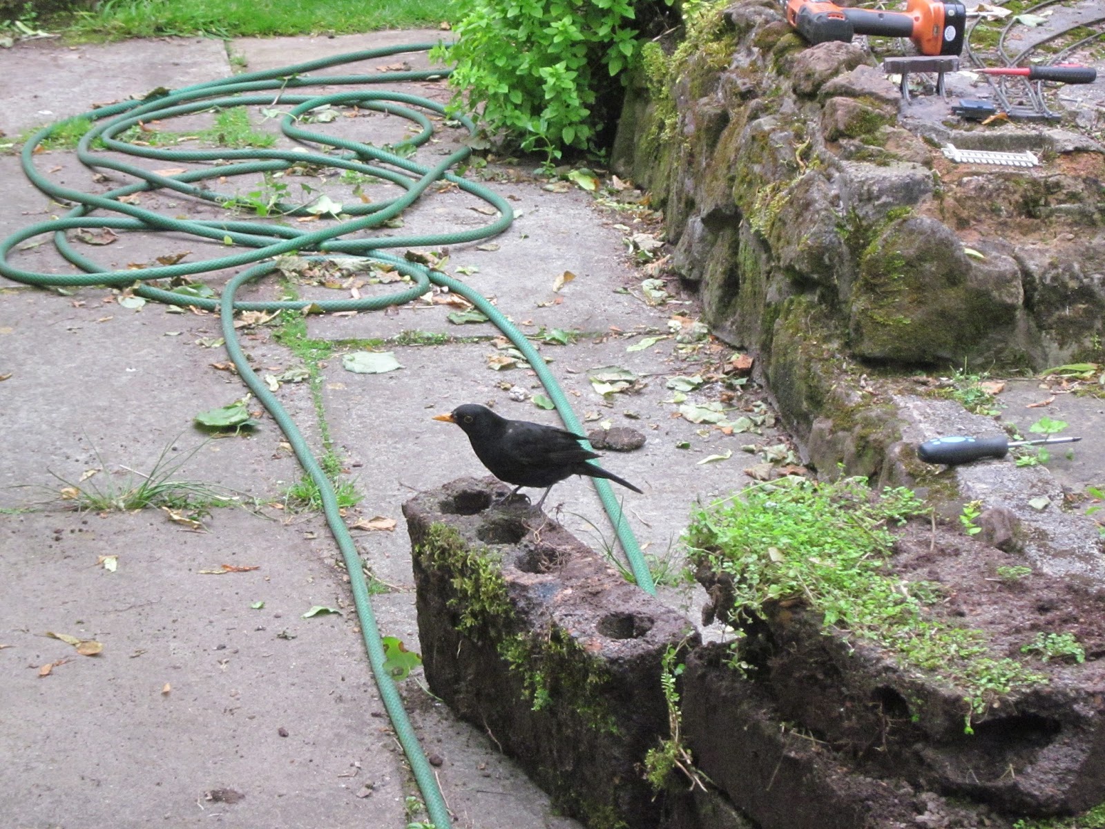
Meanwhile, one of my resident blackbirds decided to monitor proceedings and help himself to a few grubs and worms which had been exposed by my excavations.

The concrete and rocks lining the stream were then attacked with a hammer and crowbar ........

 ...... to expose the plastic liner beneath (the mill siding is in the background).

After clearing the debris, I inspected the lining. Lo and behold, there was no damage in evidence!! To double check, I ran the pump to see if any leaks became more apparent - but none appeared!

It seemed all my efforts were in vain - the leak must be elsewhere!

It was at this point, that it occurred to me that the culprit might actually be the cover for the sump. The sump is a plastic dustbin with its lid inverted, perforated and placed on top to act as a permeable cover (see How I constructed the stream).

Of course, if the holes in the cover were blocked with leaves and soil, then the water would not be able to drain back into the sump.

I removed the lid and cleaned out the sump (much to the consternation of the frogs which populate the area) and ran the stream again. Rather than needing to be topped-up after fifteen minutes as was happening previously, the stream now ran happily for two hours and even then needed only half a bucket-full to top it back up to the original level.

I try to be sanguine about such issues and so looked for the silver lining to the outcome of my labours. I had an ideal opportunity to remodel this part of the stream and provide the mill stream, I decided.

The blocks for the trackbed were re-installed (making sure they were well bedded-in); my blackbird returning to supervise proceedings.

Once all the blocks had been re-installed and levelled ......

 ...... concrete was forced into the spaces between them (I use rubber-gloved fingers for this job - much easier to get the concrete where it's needed and extremely satisfying).
 

Various chunks of sandstone were then positioned along the edges the stream, with a few in the stream bed on top of the liner, and cement forced in and around them (the concrete on the stream bed is about two inches deep). This was left to set.

The following day, a wire brush was used to remove 'green' concrete from the faces of some of the rocks and the concrete was then left for three further days to ensure it had fully set .

The track was re-instated - being fixed to the concrete blocks with Rawlplugs and screws.

The pump for the stream was then energised to check the newly installed weir and mill stream behaved as they should.

The mill-stream can be seen on the right in the middle distance. This will be built-up eventually with stonework and a set of sluice-gates will be added to restrict the flow to the wheel. I would like to simulate the ponderous turning of a real life waterwheel if that is achievable.

Looking from the opposite direction, the mill building will be installed on the plateau on the left, below the mill siding.

To check everything was functioning as it should, the cover was re-instated over the sump and the pebbles were given a thorough clean before being placed on top.

I was pleased to find that there was still minimal loss of water from the stream and so, while the civil engineering had been unnecessary to stem the leak, the modifications were now in place for the installation of the mill building (see How I constructed a water mill - pending).

Once the weather improved, the track was ballasted using my tried and tested cement and PVA method (see How I ballast my track) .......


...... and then tested.


I am pleased with the outcome. The trackbed beside the stream was in need of refurbishment as it had dropped slightly (possibly due to the rodents' excavations) and I had wanted to remodel the stream to accommodate the water mill. In addition, the ivy (which was self-propagated) had become somewhat overwhelming on this stretch and needed to be 'tamed'. And so, several objectives had been achieved - and the source of water-leakage had been explained and remedied.

It's very reassuring to know that, even after ten years of use, my technique for stream construction still holds water, so to speak -

The next job is to make the mill building and to experiment with making the sluice gates to control the flow of water to the wheel. I now have plenty of excuses to indulge in a bit more water- and concrete-play which is, of course, very important for my intellectual development.

I have already started researching the design of the mills which abounded on the River Gowy in the immediate area and realised their design had much in common ....