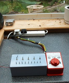
When the railway was first constructed, I relied initially on the 1 amp power supply that came with the original starter set. This proved more than adequate for controlling the line's only loco. After I'd constructed the control panel, I bought another 1/2 amp power supply in case I ever needed to run two locos independently. This set-up proved adequate in the early stages of the line.
 After a while, the tedium of having to dash in and out of the outhouse every time I wanted to adjust speed or to stop a train became too much to bear and so I invested in an Aristocraft Train Engineer remote control device and handset. Although I was using only a 1 amp transformer, I went for the 10 amp version as I intended (and still do when I can find the funds) to buy a track cleaning loco.
 This clever little unit has done sterling service for nearly two years. Acceleration deceleration is programmable so that locos slow down and speed up realistically. Even the emergency stop and reverse buttons include smooth deceleration. What's impressive is that packed into this little unit is a wealth of expansion potential. For example, you can run up to ten transmitters through the one receiver (not that I have ten rail-keen friends or relatives). Also, it is possible to put receivers in each loco and have them independently controlled. However, all I wanted was the most straightforward and simple control - a remote radio-controlled replacement to the standard controller. All I had to do was attach two wires, insert the batteries into the handset and away I went!
 Eventually, I invested in a 10 amp transformer / power supply which was quite expensive (c £60.00) but well worth the investment as it meant I'd have plenty of expansion potential for that day when the track cleaning loco or even the double Fairlie arrived!
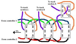
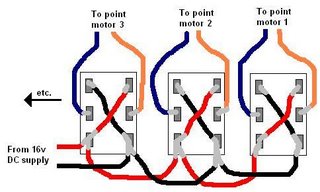
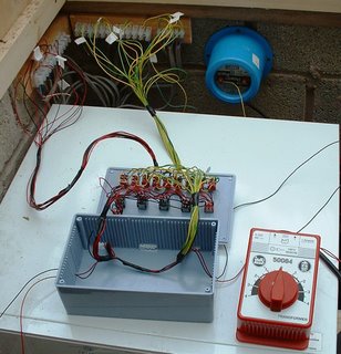
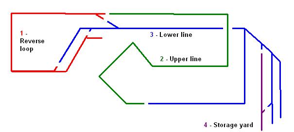
I was also considering buying the additional switch controller, which would have enabled me to switch between various sections of track and hence run more than one train at the same time. However, some unexpected back-pay was ploughed into buying a secondhand parallel MTS Central Station, transformer and handset at a very reasonable price from Garden Railway Centres. I'm not convinced the price of these products is realistic, the prices do seem overly inflated given the cost of consumer electronics these days, but it does provide me with a lot more flexibility in terms of expanding the system. Although fiddly, I found the fitting of of the decoders (£50-60 each!) quite straightforward (see How I fitted the loco decoders). In addition, I purchased a reverse loop module which detects the short-circuit created when a loco runs into or out of a loop and automatically reverses the current. Again, this was extremely straightforward to add into the wiring as I had already run the wiring from the loop back into the outhouse to the a DPDT reversing switch in the control box. Although now no longer necessary, I am keeping the control box and the electrical sections as I will still want to run unchipped locos from time to time. For example, I have a gandy dancer which I'm not going to bother to chip for those occasions when my young nephew visits.
 I was quite impressed with the system - for a while! Despite adding an extension cable to the Loco Remote (the Hornby Trains DCC cable uses the same connectors), the inconvenience of once again being tied by the cable length to the outhouse became too frustrating, particularly when I added the extension to the line. So, although I had severely overspent this year's budget, I splashed out on a wireless transmitter and receiver (which was not far short of the cost of the entire Aristo Train Engineer!).
 Although I am still a novice when it comes to DCC, I am already finding the benefits to be tremendous. Being able to independently control my four locos without having to substantially reorganise the wiring or change the pointwork opens all sorts of possibilities for operation.
However, were it not for my back-pay, I would have been more than happy to have continued with the Train Engineer, which to my mind is a far more cost effective way of getting wireless control and - had I gone down further down the route, would have provided me with almost as much flexibility.
[Update November 2013 - After dabbling with battery power and radio control, I have now abandoned track power completely and sold all my DCC equipment. I have no regrets. I find battery power far more reliable than using track power - no more track cleaning - no more tracking down electrical faults - no more faltering locos]
[Update May 2017 - I decided to make a video explaining my reasons for moving over from track power to battery power ]
<< Go to Progress Report 12
 After a while, the tedium of having to dash in and out of the outhouse every time I wanted to adjust speed or to stop a train became too much to bear and so I invested in an Aristocraft Train Engineer remote control device and handset. Although I was using only a 1 amp transformer, I went for the 10 amp version as I intended (and still do when I can find the funds) to buy a track cleaning loco.
 This clever little unit has done sterling service for nearly two years. Acceleration deceleration is programmable so that locos slow down and speed up realistically. Even the emergency stop and reverse buttons include smooth deceleration. What's impressive is that packed into this little unit is a wealth of expansion potential. For example, you can run up to ten transmitters through the one receiver (not that I have ten rail-keen friends or relatives). Also, it is possible to put receivers in each loco and have them independently controlled. However, all I wanted was the most straightforward and simple control - a remote radio-controlled replacement to the standard controller. All I had to do was attach two wires, insert the batteries into the handset and away I went!
 Eventually, I invested in a 10 amp transformer / power supply which was quite expensive (c £60.00) but well worth the investment as it meant I'd have plenty of expansion potential for that day when the track cleaning loco or even the double Fairlie arrived!
I was also considering buying the additional switch controller, which would have enabled me to switch between various sections of track and hence run more than one train at the same time. However, some unexpected back-pay was ploughed into buying a secondhand parallel MTS Central Station, transformer and handset at a very reasonable price from Garden Railway Centres. I'm not convinced the price of these products is realistic, the prices do seem overly inflated given the cost of consumer electronics these days, but it does provide me with a lot more flexibility in terms of expanding the system. Although fiddly, I found the fitting of of the decoders (£50-60 each!) quite straightforward (see How I fitted the loco decoders). In addition, I purchased a reverse loop module which detects the short-circuit created when a loco runs into or out of a loop and automatically reverses the current. Again, this was extremely straightforward to add into the wiring as I had already run the wiring from the loop back into the outhouse to the a DPDT reversing switch in the control box. Although now no longer necessary, I am keeping the control box and the electrical sections as I will still want to run unchipped locos from time to time. For example, I have a gandy dancer which I'm not going to bother to chip for those occasions when my young nephew visits.
 I was quite impressed with the system - for a while! Despite adding an extension cable to the Loco Remote (the Hornby Trains DCC cable uses the same connectors), the inconvenience of once again being tied by the cable length to the outhouse became too frustrating, particularly when I added the extension to the line. So, although I had severely overspent this year's budget, I splashed out on a wireless transmitter and receiver (which was not far short of the cost of the entire Aristo Train Engineer!).
 Although I am still a novice when it comes to DCC, I am already finding the benefits to be tremendous. Being able to independently control my four locos without having to substantially reorganise the wiring or change the pointwork opens all sorts of possibilities for operation.
However, were it not for my back-pay, I would have been more than happy to have continued with the Train Engineer, which to my mind is a far more cost effective way of getting wireless control and - had I gone down further down the route, would have provided me with almost as much flexibility.
[Update November 2013 - After dabbling with battery power and radio control, I have now abandoned track power completely and sold all my DCC equipment. I have no regrets. I find battery power far more reliable than using track power - no more track cleaning - no more tracking down electrical faults - no more faltering locos]
[Update May 2017 - I decided to make a video explaining my reasons for moving over from track power to battery power ]
<< Go to Progress Report 12