Although many narrow gauge light railways in the UK were not signalled, I felt that the level of traffic on my railway was sufficiently complex to make signalling a necessity. A visit from a fellow garden railway modeller, who also happened to be a full time railway signalman, provided me with a series of signalling diagrams for each station showing the requirements are three levels of complexity (see
Progress Report 36). I opted for the most basic level of signalling, though even this called for the construction of 20 signals on 19 posts - on average four signals per station.
Background research
Before deciding on the best approach for meeting my identified needs I did some background research. Firstly, I looked at various readymade signals and kits in 16mm scale which were available. These ranged in price and complexity from
Cambrian Models' kit of plastic parts (including a ladder but not including the post) for £6.35, a readymade signal for £8 from
Modeltown , a kit of intricate metal parts for £30 (
from MSE)
, readymade signals from
Treddol Designs for £32, through to bespoke hand-made signals from
Charlie Harrison (price on application).
 |
| Modeltown signal - source: http://www.modeltown.go-ecommerce.com/shopping/site/Product/signal-ebm17-1274003 |
 |
| Example of a bespoke signal from Charlie Harrison - Source: http://www.users.waitrose.com/~chazharrison/16mm%20signals%20page.htm |
Even the cheapest of the above approaches would have cost me at least £160 to meet my needs and, as funds were tight, I decided my only option was to construct my own.
After consulting a series of articles published in the
Garden Rail magazine, I felt I had accumulated sufficient background knowledge to tackle the task.
I decided to batch build all 19 signals at the same time as I felt this would be the most cost-effective approach in terms of both time and financial outlay - though one signal was constructed initially to test out my ideas and act as a prototype.
The posts
The most obvious place to start seemed to be the signal post - after all, on this everything else would hang! I considered using square section brass rod and square section plastic but eventually opted for wood. After rejecting balsa wood and softwood I decided to track down a source of 12mm square section hardwood. Unfortunately, I could not track down a source for 12mm stripwood but I did find a supplier of 12mm x 6mm section. As they came in lengths of 60cm, it seemed reasonable that the default height for the signals would be 30cm (or 20ft in 15mm scale).
The first job was to glue the stripwood sections together to form 12mm square posts.
This was achieved with exterior grade PVA, the sections being clamped together until the glue set.
On reflection, I could have embedded two strips of copper tape between the strips at this stage to provide a means of powering the signal lamp LED (see below) - such is the benefit of hindsight!
I could have been content with leaving the posts in square section for their entire height but decided that a gentle taper of 1mm on each of the four sides would give the signals a more realistic appearance. The problem was, how to create a consistent taper on all 19 posts. After attempting to plane and sand down one post by hand, I quickly realised that it would be impractical to achieve the same with another 18. I needed a more systematic and efficient approach. Having recently invested in a power planer, I felt sure there would be some way of using this to meet my objective.
I constructed a jig which would hold seven posts alongside each other. Softwood sides slightly deep than 12mm were added to a plywood base to hold seven posts side by side. To raise one end of each post, a length of 2mm thick brass strip was placed at the end of the jig and the posts rested on it.
 |
| Jig to hold the posts while being planed - showing the brass strip needed to raise the ends |
The planer was set to cut 0.5mm depth and a few passes were made until 2mm had been removed from the first side of the posts. The posts were then rotated through 90 degrees and the process repeated to remove up to 2mm from the second side.
The posts were removed from the jig and another brass strip was then placed on top of the first strip and the posts rotated and replaced in the jig before the third side of each post was shaved. They were then rotated a third time and the last side tapered off. As the posts became increasingly tapered it was necessary to place a wooden wedge in the jig to stop the posts from rattling around as the planer passed over them
The process was not perfect. Some posts ended up with slightly greater tapers than others, possibly because the planer lifted them as it passed over, and a
couple of posts split at the end along their grain (see below), but the time and effort saved
was well worth the time taken to construct the jig.
The two posts with split ends were shortened - in the real world, the heights of signal posts were often tailored to suit the topography of their location.
The posts were then given a coat of wood primer followed by two coats of domestic satin white paint.
The finial
I wondered whether to add finials to the top of the posts in case they became an eye-poke risk when leaning over the railway. However, after some experimentation with the prototype signal, I decided the added appearance of a finial on each signal more than balanced the potential health and safety risk.
Several cocktail sticks were cut in half and the pointed ends blunted slightly with a piece of sandpaper. These were painted satin white and when dry, a small red wooden bead (50p a bag from eBay) was threaded on. A 2mm hole was drilled in the top of each post and the finial glued in place with exterior PVA. A dollop of decorators' filler was then moulded into the space between the top of the post and the bottom of the bead to finish it off.
Signal arms
For me, the next most significant component was the arm. For strength and durability, I decided to construct these from 12mm wide x 0.6mm (25thou) thick brass strip.
The arms were 65mm long with a triangle of base 5mm removed from one end.
12mm square pivot plates for
the ends of the arms were marked out on another piece of 12mm wide brass
strip. Each square pivot plate had an additional triangle with a 5mm base added to match that on the arms.
A centre punch was used to make the bolt heads on the diagonals and to mark the position of the pivot in the centre........
...... before the pivot plates were then removed from the strip with a pair of tin snips.
A 1.2mm hole was then drilled in the centre of each plate for the pivot.
Spectacles
For the spectacle frames, copper wire was removed from some 13 amp twin and earth mains cable.
A jig was made from a couple of pieces of plastic dowel from a ball-point pen inserted into holes in a piece of softwood. The wire was bent at 90 degrees and then wound around the dowels.
..... before being snipped to length...........
..... producing a series of spectacle frames of approximately comparable shapes and sizes.
Constructing the arm
Another simple jig was made to hold the various parts in place while they were bring soldered. This jig comprised a few brass tacks tapped into a piece of softwood (the same piece as used for the above jig) in strategic places and a hole drilled through for the pivot. A 30mm length of 1mm dia brass rod was then placed in the hole (the longer peg in the picture) ......
.... before the signal arm, with a suitably drilled 1.2mm hole, was placed over it and some solder applied with my trusty 70watt iron.
The pivot plate and spectacle frame were then positioned .......
........ before being soldered into place.
The arms were then given a couple of coats of Halfords grey primer from a rattle can, before being masked with masking tape: with a 10mm wide strip 12mm from the end for the front white and back black stripes, the backs were masked and the spectacle, pivot and pivot plates were also masked. The signals were then given two coats of red Plastikote from an aerosol can.
The backs of the arms were painted white acrylic and the stripe, pivot plates and spectacles painted black acrylic.
Oblongs of red and green acetate were glued to the spectacle frames with clear Bostik. I had tried Superglue and epoxy without success and found Bostik to be the most effective, though probably the trickiest to apply cleanly.
The acetate pieces were clamped between a couple of pieces of stripwood while the glue set. ........
..... and then the excess trimmed off with a pair of nail scissors.
A 2.5mm hole was drilled through the top of each post, 20mm from the top and a piece of 2.4mm (3/16") OD brass tube was superglued into the hole, making sure the tube stood proud either side by about 0.5mm.
The pivot for the arm was then slotted into the tube and bent over at 90 degrees to coincide with the division between the red and green spectacle glasses. This would form the mount for the spectacle lamp shutter (see below).
The signal lamp
After experimenting with a couple of options, including turning lamps from wood in an power drill, I went for the following approach as it would allow me to insert an LED. The body for the lamp was a 7mm piece of 6mm square Plastruct tube. A 1.5mm hole was then drilled in the centre of one side and out through the opposite side.
One of these holes was then opened out to 3mm diameter with a round needle file. This was a lot more controllable than trying to open it out with a 3mm drill which tended to wander.
A 1mm thick 'washer' was cut from a length of 4mm OD Plastruct tube and glued to the front of the lamp.
The lamp body was then glued to a piece of 1.5mm thick plasticard and once set, was trimmed off and bevelled with a piece of fine grade emery paper to make a cap. A 2mm thick washer was cut from 4mm OD tube and a cap punched from 1.5mm thick plasticard using a hole punch. The cap was also bevelled with sand paper and before the tube and cap were added to the lamp body for a chimney.
The lamp was then given a couple of coats of matt black acrylic paint inside and out. After purchasing a variety of LED powered flickering tealights I tracked down one which used 3mm LEDs without an additional circuit board (some lights have 5mm LEDs and others have a small circuit board to give a flicker to a standard LED).
These came from my local 50p shop. The leads to the LED were bent through 90 degrees and the LED inserted into the lamp to shine through the front.
The inside of the lamp was then flooded with clear Bostik to hold the LED in place.
A 10mm x 20mm base for each lamp was cut from 1.5mm plasticard and two 2mm holes drilled as shown for the LED leads.
The lamp was then glued to the base.
Lamp bracket
To support the lamp, 7.5mm wide brackets were cut from a length of 10mm x 10mm wide brass angle.
Two 1mm holes were drilled in one side of each bracket roughly 3mm from the edges.
10mm lengths of 1mm diameter brass rod were then soldered into the holes ......
.... and any excess solder removed with a file.
The brackets were then given a couple of coats of black primer.
Shutters for the lamps with a radius of 1.8mm were marked out a piece of 0.6mm thick brass using a card template.
The concave arc of each shutter was filed before removing them from the sheet as this made them easier to hold in the vice.
The shutters were then cut from the sheet with snips and tidied up with a file.
After marking the position of pivot and allowing 1.5mm for the thickness of the base, two 1mm holes were drilled in the side of the signal using the pegs on the bracket to guide their exact position. This would account for any slight variation in the positioning of the pegs on each bracket.
The bracket was then superglued to the post. At this point some wriggling was done to ensure the brackets were vertically aligned - the 'give' in the brass pins and the wood allowed for a few thou' movement.
The lamp was then superglued to the bracket (the base was left unpainted to ensure a good key between it and the bracket).
The arm for the shutter was then snipped off just beyond the lamp .....
.... and the end tinned.
The back of the shutter was also tinned (note the card template in the background).
The shutter was then soldered on to the tinned arm and both were given a couple of coats of matt black primer.
The balance-arm
The 75mm x 4mm balance arm was cut from 0.8mm (32thou) brass sheet with snips. The thickness of the metal caused the strip to curl as it was cut ...........
......... and so it needed to be persuaded to straighten out using a couple of pairs of pliers, ........
..... a hammer and anvil and a fair amount of brute strength.
Once straightened, the ends were rounded off with a file
.... and three 1mm holes were drilled; 5mm, 15mm and 25mm from one end.
The 2.5mm thick balance weights were cut from a length of 12mm diameter brass rod.
The balance weights were then soldered on to the balance arm, 5mm from the opposite end to the holes and the arm was given a couple of coats of 'Chaos' matt black primer from an aerosol can.
To make the pivot plate for the arm, 40mm x 5mm strips were cut from a piece of 0.6mm thick brass sheet. The ends of the plate were then rounded off with a file.
1mm diameter holes were then drilled 5mm from each end and the plate was folded through 90 degrees, 15mm from one end.
A piece of 1.6mm thick brass strip was screwed to a length of softwood and the plate was inserted beneath it ...........
....... and after a few blows with the hammer, the plate was folded through 180 degrees.
After removal from the bending-jig, the hole on the shorter flap of the plate was used to guide the drilling of a 1mm hole in the opposing longer flap. This will hold the pivot for the balance arm.
A 10 mm length of 1mm diameter brass rod was inserted into a hole in a piece of softwood and the hole in the end of the pivot plate located over it.
The rod was then soldered into place. Trying to hold such small parts steady while heat is applied from the iron requires this sort of approach to be adopted, unless you have asbestos finger-tips (which I do not!).
A 15mm length of 1mm diameter rod was then inserted into a hole in the softwood and the pivot plate and arm was located over it - the rod passing through the middle hole in the arm.
The pivot was then soldered into place. I did try masking the arm with newspaper to prevent the solder from gumming up the pivot, but found it to be unnecessary.
The upper ends of the pivot peg and other locating peg were filed down and excess solder removed to give a tidy appearance. The whole assembly was then given a couple of coats of black primer. I had wondered if the primer would gum up the works, but using an aerosol spray ensured the coats were thin and did not adversely affect the swinging of the arm.
Once dry, a 1mm hole was drilled 40mm from the base of the signal to accommodate the pivot arm peg and another drilled above it to take the upper peg on the plate. The drilling was tailored to each plate to account for any slight variation when the plates were being folded.
The pivot arm assembly was then fixed to the base of the post with a dab of superglue in each hole.
Ladders
After pricing various commercially made signal ladders, I decided for financial reasons I would need to construct my own. As I needed 19 ladders, I decided to make a jig to enable several ladders to be constructed at once.
A 27cm x 34cm piece of 17mm ply provided the base for the jig. A 17cm x 24cm piece of 17mm thick plywood was screwed to the base, leaving a 10cm border along two edges. Two pieces of 5cm wide ply (one 17cm long and the other 24cm long) were screwed on to these borders with slotted holes to allow them to slide. A grid of 10mm x 15mm lines was drawn on the 17cm x 24cm piece of ply and copper nails were hammered along two sides of the grid and into the two strips to coincide with the grid lines (see photo below). A length of copper wire (from 13 amp twin and earth cable) was wound to and fro across one set of pegs in a form of 'warp', keeping the strands as taut as possible.
Then a 'weft' of cable was wound across the pegs at right angles. Some adjustment was necessary to ensure the wires followed the grid. In hindsight, I should have positioned the pegs to one side of the grid lines, anticipating the direction the wire would take around each peg.
Wooden wedges were then hammered into the gaps between the main section of the jig and the movable side pieces to further tauten the wires. The screws in the slotted holes were then tightened to hold the side pieces firmly in place.
The intersections between the wires were then soldered to bind them together.
This process was repeated across every intersection on the jig - a somewhat tedious and time consuming process - but worth the effort, ultimately!
Once all the intersections had been soldered, the screws were eased and the wedges removed. With the tension eased, the wires were snipped between the pegs and the lattice removed from the jig.
The wires between the individual ladders were then snipped away.
Closer scrutiny showed that the ladders needed to be tidied-up. Any excess ends of wires were snipped off .........
....... before the ends of the wires were filed smooth.
Unnecessary globules of solder were filed from between the rungs with a square file ......
..... until each ladder looked acceptable.
To form the safety hoop at the top of each ladder, some wire was wrapped around a fat felt tip pen barrel .......
...... and the legs bent to shape.
The ends of the hoop were then inserted into holes drilled in the ubiquitous piece of softwood used previously .....
...... before being soldered to the top of the ladder.
The ladders were then given a couple of coats of black primer from an aerosol spray can.
To attach the ladders to the post, a 1.5mm hole was drilled through the post just below the lamp bracket ......
...... and the ends of the hoop were bent through 90 degrees and pushed into the holes either side of the post. They were left 'flapping' at this stage until the bases had been completed.
The bases
After a quick survey of the railway to determine the positions of
the signals, I realised that some would be located on firm ground (ie
the concrete or wooden trackbed) whilst others would be positioned beside the trackbed in soil. As I wanted the signals to be removable, I recognised that they would need two types of base - a plate base for those on firm surfaces and a slab base for those which would be located on the soil. On reflection, I could have cast concrete slabs in the soil in situ and made all the signals with plate bases.
Plate bases
For the plate base, a piece of 75mm x 25mm x 1.6mm thick brass strip was cut, as were four 12mm wide pieces of 10mm x 10mm brass angle.
These were tinned with solder, using my 70watt iron.
The brackets were then soldered to the plate bases with a blow torch as I found the heat dissipated too quickly if I tried using the iron to fix the brackets to the base.
To locate the plate bases in their positions on the railway, I used three brass nails.
The head of each nail was removed and it was pushed into a 2mm hole drilled in the base and soldered into place (note the other two holes in the photo are for the base of the ladder.).
For locating the signals on the wooden trackbed, three holes were drilled to take the pins.
For those on concrete or breeze block trackbeds, larger holes were drilled with a masonry bit and plastic rawlplugs inserted. These were then drilled with a 2mm hole to take the pins.
Slab bases
To hold the signals upright while the quick-setting cement and sand mix dried, a simple frame was made from a sheet of plywood. a couple of lengths of softwood and a piece of stripwood into which slots had been cut to hold the posts.
The bottom ends of the ladder on each signal was bent through 90 degrees and the ends wrapped around the base of the post. The bottom of each signal was then placed in a plastic drawer from a set of storage drawers (normally used to hold screws and small components). I experimented with various sorts of plastic sheet and greaseproof paper to protect the drawers from the cement - I found the best bases were those cast in the unlined drawers - there was no problem with the cement attacking, staining or sticking to the plastic of the drawers.
The cement and sand (1:4 mix) was mixed with water to a runny consistency and poured into the moulds. It was left overnight to ensure it was thoroughly set. On reflection, I should have included some reinforcement strands or aggregate in the cement mix as some of the bases split on removal from the moulds and had to be glued back together with epoxy.
To finish off the signals, 1mm holes were drilled in the signal arm 5mm from the pivot and a length of 1mm diameter brass rod was cut to length to link the signal arm to the balance arm. Brass nails with their heads removed were positioned above and below the balance arm to limit the movement. The posts were then masked off just above the balance arm assembly ......
........ and all the signals given a couple of coats of black primer from an aerosol can.
Powering the signal lamps
At this point, I turned my attention to finding a way of getting power to the LEDs in the lamps. I should have considered this far earlier in the build and, as indicated above, could have secreted the leads between the two pieces of wood which form the post.
Inspiration struck when I espied some self adhesive copper tape which my wife was using to deter slugs and snails from climbing up her planters in the garden.
3mm wide strips of copper tape were cut and then fixed to the side of the post behind the ladder .......
..... running from top to bottom. A short length of wire was soldered from the top of the tape to the positive lead of the LED. Another short lead connected the negative lead of the LED to the ladder. At the base of the signal, one lead was soldered to the bottom of the tape and another to the bottom of the ladder (or to the plate base).
These leads were then connected to a battery for testing.
The copper tape was then touched up with white and black paint to disguise its appearance.
Operation
Deployment
The signals were positioned around the railway, following the suggestions provided by my signalman friend (see
Progress Report 36).
 |
| One of the starter signals at Beeston Market - the signal box and home signals in the background. |
 |
| The double home signal controlling the approach to Beeston Market |
 |
| The home signal controlling the approach to Beeston Castle from Peckforton. |
 |
| The home signal controlling the approach to Peckforton from Beeston Castle |
 |
| The home signal on the approach to Bulkeley from Bickerton |
 |
| One of the starter signals at Bickerton |
To ensure the signals are placed in the correct positions (ie the pegs beneath each post base vary slightly in their relative positions), the signals are stored on a piece of 7.5mm thick balsa wood which is labelled with to show each signal's location.
Control
At present, I only deploy the signals when I am intending to conduct a full timetabled operating session. Although they are operational, they are currently only cosmetic. I am considering various options for making them fully operational.
1. Mechanical
For the signals at the two termini; Beeston Market and Bickerton; I am considering the installation of lever frames and some sort of mechanical linkage, similar to that used on
Grant LNR's railway
 |
| Source: http://www.gardenrailwayclub.com/landscaping/signals/An-Interlocked-Semaphore-Signal |
The difficulty which I will need to overcome, in addition to making the system weatherproof, is to find some way of making the signals detachable from their linkages as I will not want to leave the signals out for prolonged periods. I am concerned about their fragility and their susceptibility to damage, not only by animals which invade the garden, but also my clumsiness when gardening.
The advantages of a mechanical system are its simplicity, its lack of electrical components and also the way it mirrors the real thing. I will, however, need to devise some means of powering the LEDs, either through individual battery boxes or via some sort of wiring loom. Given that this will require some sort of hybrid system, it might well be more cost- and time-effective to opt for an entirely electrical system for controlling all signals. I am, at present , considering two approaches.
2. Radio control
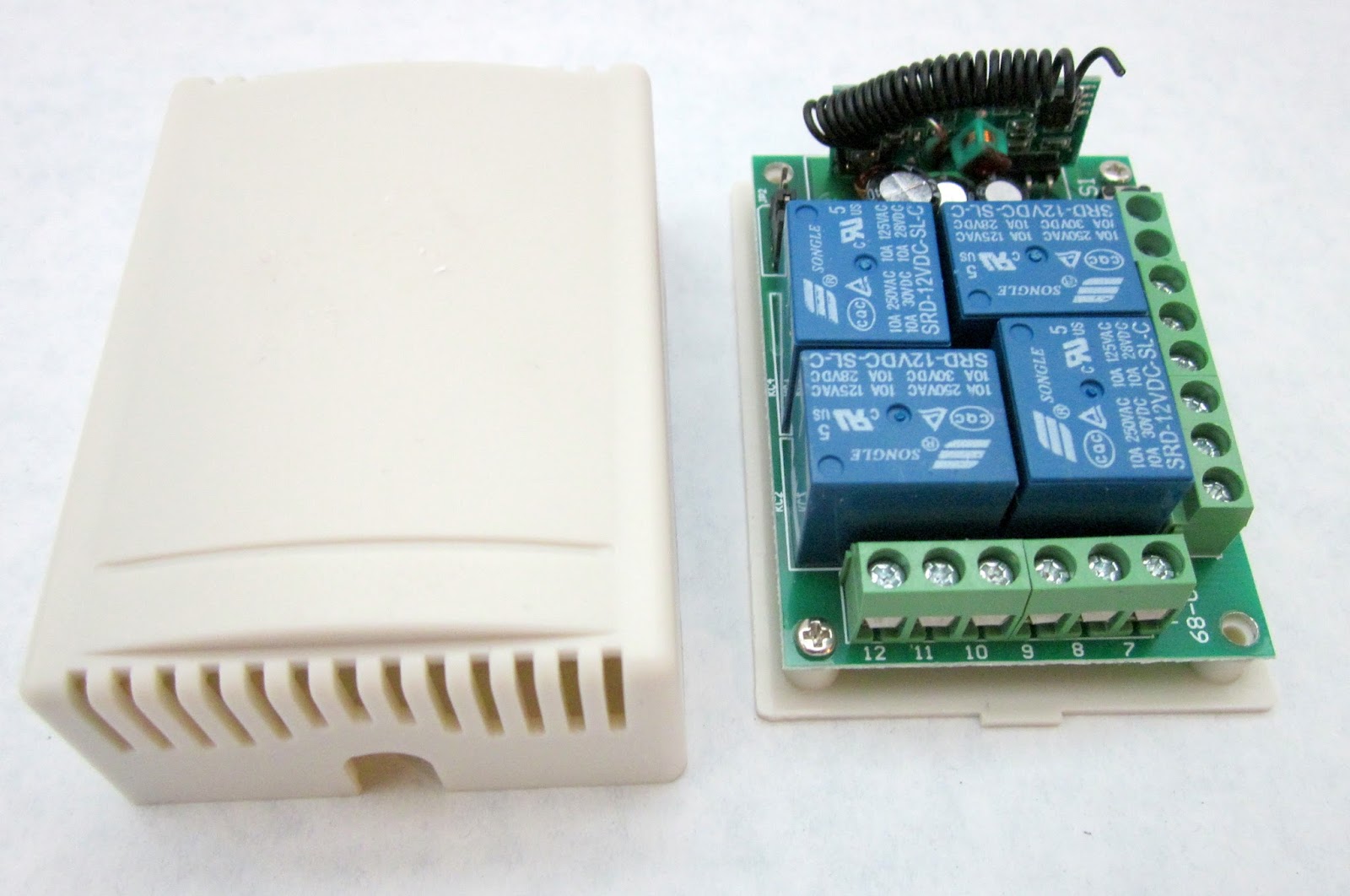
Each signal will have its own servo which will be operated through a receiver. Initially, ad rejected this idea as being prohibitive in terms of cost, but with the development of Deltang's tailored r/c system for the operation of points and signals (see
http://deltang.co.uk/tx27a.htm) this approach will become more within my reach.
 |
| Deltang Tx27 points/signal control transmitter |
With each receiver/controller able to operate up to five signals, this coincides nicely with the deployment of signals around my layout where there are four signals per station. The system would require the installation of a wiring loom to interlink each each signal servo to the receiver/controller and also to power the LEDs but this could be achieved with a weatherproof multi-pin plug beside each signal. In addition, each servo would need to be made weatherproof but as there are already servos available which are designed to be used on r/c boats, this should not prove too problematic.
3. DCC control
Another option is to continue using the existing wiring for DCC track control. The system is already in use to control some of the more remotely located pointwork (see
Progress Report 39). Each station would need a decoder which is programmed to operate the servos or point motors to operate the signals. However, despite having the existing DCC infrastructure, the purchase of decoders and point motors would be far more expensive than purchasing the components and servos needed for the Deltang system. Furthermore, once I migrate fully over to the radio control of locos, I will be able to sell on my DCC hardware and realise the capital locked up in it.
Conclusion
As with most of my projects, now I have completed it, I now know how to do it properly. However, I hope my experiences and above musings will prove useful for anyone intending to make their own signals.
With the benefit of hindsight, were I to embark on this project again I would:
- Consider how the LEDs would be powered from the start of construction - eg I could have embedded the copper tape between the two halves of the posts.
- Placed all signals on plate bases rather than casting some in concrete. I would have then cast bases in situ for each signal alongside the trackbed.
- Incorporated the control system for each signal into the construction - though this would have involved a greater initial outlay which at the time I could not have afforded. However, had I experimented on one signal to discover how the operating mechanism might affect the eventual design and construction.



.jpg)
.jpg)
.jpg)


