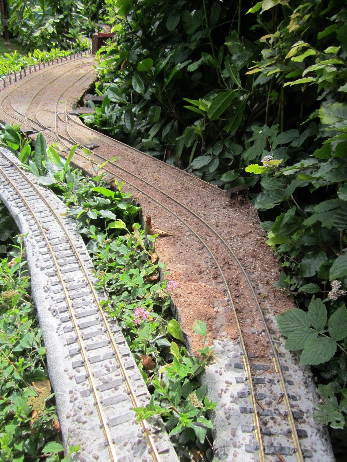
This Blog describes the ongoing development of a 16mm scale 45mm gauge garden railway situated in the North West of England, UK from 2004 to the present day.
Having previously constructed a Manning Wardle 0-6-0 locomotive using a Piko motor block (see How I constructed a Manning Wardle 0-6-0T loco), I decided it was about time I provided her with sound. As with three of my locos, I invested in a MyLocoSound steam soundcard. The more recent Universal card is not only adjusted using an infra red remote control rather than using onboard preset potentiometers, it includes sound effects in addition to the conventional steam whistle. These effects include a guard's whistle, a bell (or short steam whistle), the sound of a safety valve blowing off and an air pump. The effects can be triggered by the remote control or through a receiver and transmitter with the requisite number of spare channels.
Having recently constructed a Deltang Tx20 transmitter (see How I constructed a Deltang Tx20 transmitter kit) which includes two push-buttons to operate Channels 2 and 4, I decided it was worth investigating whether I could use these, together with the bind button and direction switches, to trigger the additional sound effects on the soundcard.
What I wanted was:
To sound the whistle when the bind button was pressed (Ch5 low)
To start and stop the safety valve effect when button 1 was pressed (Ch2 low)
To sound the guard's whistle when button 2 was pressed (Ch4 low)
To sound the bell when the direction switch was flicked left (Ch3 high)
To start and stop the air pump when the direction switch was flicked right (Ch3 low)
A quick consultation of the chart showing the Rx65b's features on the Deltang website .......
Pad 3 gives an output of 0v when Ch2 goes low (ie the button on the Tx is pressed)
Pad 4gives an output of 0v when Ch4 is energised (ie the other button on the Tx is pressed)
Pad 6 gives an output of 3.5v when Ch3 goes low (ie the direction switch on the Tx is flicked down)
Pad 7 gives an output of 3.5v when Ch3 goes high (ie the direction switch is flicked up)
The only problem was that the inputs on the MyLocoSound card are triggered when they are connected to 0v (ie to 'ground' or the negative lead from the battery). This meant that the outputs from Pads 3 and 4 would be fine for triggering the card's inputs, but the outputs from pads 6 and 7 were the inverse of what was needed.
I could have reprogrammed the pads to give 0v outputs (see How to program Deltang receivers), but decided that I would experiment with another way of achieving the same outcome, as I would be posting my findings on this blog and I know many people are daunted by the prospect of programming. Fortunately, I discovered that the output could be inverted using a simple transistor circuit:
After consulting David T at Deltang, who advised me that the circuit would be fine and that I could use the voltage from the input terminal of the soundcard (which is around 5v) provided the 1k resistor was connected between the transistor circuit and the soundcard. He also suggested that all connections between the Rx65 and the soundcard should be protected from the risk of excess current by connecting a 1k resistor between the outputs from the pads and the terminals of the soundcard.
As there were only three components required, I decided to solder them together directly ......
.... and then shroud all the connections in heatshrink sleeving.
The leads from the 10k resistors (on the base leads of the transistors) were then soldered to the pads 6 and 7 of the Rx65, and the emitter leads of the transistors were soldered to two of the negative pads on the Rx65.
The rx with its attached transistors were then shrouded in an additional layer of heatshrink sleeving for added protection.
Flying leads from the 1k resistors (on the collector leads of the
transistors) were then connected to the relevant screw terminals on the
soundcard.
With everything connected, the loco and card were ready for testing. And then the loco was reassembled and ready for test running.
With most aspects of garden railway modelling, there are often many solutions to any given problem. I could have reprogrammed any of the pads on the Rx65 to provide the 0v required, I could have connected a switcher unit to the servo output from pad 10 or I could have even used a completely separate receiver for controlling the soundcard, as I have done on another of my locos (see How I used Deltang receivers to trigger sounds on a Technobots soundcard). There are probably many other solutions, but we all tend to stick with the areas of knowledge with which we feel most comfortable, and as long as it works .....
A few things have developed since my last report at the end of May. On the motive power front, he most significant has been the completion of the railway's twelfth locomotive, a Simplex diesel (Emma). Further, on the motive power front, various locos have been through the workshops for routine maintenance and, in the case of Manning Wardle Loco No. 6 (Harthill), some modification. In addition, Hunslet loco No. 3 (Bickerton) is in the process of being converted from track to battery power
There have been some developments with rolling stock - four new wagons have entered service and a couple of these, plus another two wagons, have been weathered.
The track has received some attention with, in particular, ballasting in and around the Copper Mine. There has also been ongoing track maintenance around the railway though this year, having gone over completely to battery power, the maintenance has been less onerous - there being no need now to worry about electrical continuity through the whole network.
Some lineside work has also been carried out, though on a limited scale compared with other developments. The staithes in the coal yard have now been completed, as has the plate girder bridge carrying the feeder line over the sidings at the Copper Mine. I have also, at long last, replaced the fencing separating the Copper Mine sidings from the main line.
History has been made - a live steam locomotive has run on Peckforton Light Railway metals for the first time - and finally, I have also managed to run some trains.
Motive Power
As indicated above, the PLR now has twelve locomotives, eight of which are battery powered and run on the 45mm gauge main line, two are presently track-powered and awaiting conversion to battery power and two are primarily 32mm gauge to run on the feeder railway for the Copper Mine. The most recently completed loco is a plate frame Simplex which was built from an IP Engineering kit. This is actually dual gauge as I have two chassis which will slot in - one 32mm gauge and the other 45mm gauge.
IP Engineering Simplex
After completing the kit according to the instructions, ...
... I decided to modify it by adding more detail to the engine compartment and adding a cab.
Paint-finish
I experimented with a different type of paint-finish on this loco. After applying the primer, I applied rust colour to those areas which I thought would be most susceptible and then sprinkled crushed sea salt crystals on. After a couple of coats of the final colour, the rusty areas were abraded slightly to remove the paint and then rinsed in warm water, exposing the rust colour beneath apparently peeling paint. Some of the salt is still present under the top coat, but this gives the impression of rust bubbling up beneath. I'm not certain I have perfected the technique as yet, but to my mind it does seem to give a reasonable impression of corrosion.
Power and control
She has been equipped with two 14500 (AA sized) li-ion batteries wired in parallel to give extended running time. She also has a Deltang Rx65b receiver/controller which is hidden in the double wall of the cab side (nearest the camera in the above photo). I felt the receiver would be more reliable if placed in a plasticard cab than under the whitemetal bonnet of the engine compartment.
Sound system
I have also provided her with a very basic sound system, using a small module intended for use inside musical greetings cards.(seeHow I modified a greetings card sound module). The unit was cut down to remove the on-board batteries so it would fit inside the engine compartment, and then wired into the batteries of the loco. Whilst the sound is not remarkable, it does add an little something extra - and for under £1.50 (UKP) it certainly seems good value for money.
Chain drive
For a while, I ran the 45mm gauge chassis unaltered and was not overly impressed with the loco's hauling capabilities (3 or four skips on the level and down hill) -
However, after adding chain drive to turn her into a 4x4.....
..... the difference was, to my mind, quite amazing.
As indicated above, two of my former track-powered locos are awaiting conversion to battery power.
Loco No. 3 Hunslet 0-4-0 - Bickerton
This is presently in the process of being converted. Her saddle tank was crammed full of lead weights to make her a whacking 2.2kg and I have been putting off tackling her conversion as I knew I would have to remove these weights to create space for the batteries. As she was constructed from a Garden Railway Specialists (GRS) resin kit, I was very concerned about dismantling her in case I damaged the fragile castings and yet the only way of removing the weights was to dismantle her into her various cast components.
I was pleasantly surprised to find that once I started prising apart the epoxied boiler assembly from the running plate and cab with a flat-bladed screwdriver, the two main components came apart quite easily with no irreparable damage. Furthermore, the clear Bostik adhesive holding the lead weights also parted with a little persuasion and so the loco is now ready for the next stage of conversion.
I found there was room in the saddle tank for three 3Ah 18650 tagged li-ion batteries with room to spare for some sheets of lead flashing. The battery protection board will fit into to lower half of the boiler and when funds permit, I will install the Deltang rx65b receiver/ controller into the firebox.
When she has been reconstructed an opportunity will be taken to give her a respray; her paintwork was beginning to show signs of wear and tear.
My other battery loco (No. 7 - Fowler 0-4-0DM - Tollemache) will be converted later in the year as funds permit.
General loco maintenance
Maintenance, of course, is an ongoing task but I thought I'd just give an insight into the types of jobs which crop up when running a garden railway for those who are considering participating in this fascinating albeit somewhat time-consuming hobby.
Loco No. 6 - Harthill
This loco was scratchbuilt by me on a Piko 0-6-0 motor block (see How I constructed a Manning Wardle 0-6-0T). She is based on one of the Manning Wardle locos which ran briefly on the Davington Light Railway during the First World War before being shipped to Brazil.
She is one of my favourite locos as she runs very smoothly and is very responsive to her Deltang rx65b receiver/controller. A month or so ago, her MyLocoSound soundcard stopped working quite abruptly and, as it was still covered by warranty, was sent back to Peter Spoerer (the UK supplier) for a check-up. It turned out that the card itself was faultless and so we traced its problem to the small speaker which I had installed in the loco's cab. This was replaced with one of Peter's speakers (which I should have used in the first place), and the soundcard re-installed. Of course, it now works perfectly! Lesson learned - use the speakers which are recommended for use with the soundcard rather than trying to find a cheaper alternative (not that Peter's speakers are costly).
While she was in the workshop I decided to correct a constructional detail which was pointed out to me by a fellow garden railway modeller. I had pitched the cylinders and motion at too steep an angle rather than aligning the piston rod with the centre of the wheel to which the connecting rod was connected.
Fortunately, the re-positioning was not too onerous - the ends of the slide bars were desoldered from their hangers and then re-soldered higher up. As the cylinders were each fixed in place with a single bolt, they simply swivelled to their new orientation.
To improve the appearance of the crosshead, a plasticard overlay was shaped and superglued to the original plain brass crosshead and given a coat of silver acrylic before being lightly weathered.
I felt it was time to install a more appropriate figure, so a ModelTown driver was painted and glued in place of the LGB figure.
The rather garish pink batteries which were installed in the cab we also given a coat of matt black acrylic paint while the roof of the cab was removed.
Loco No. 8 - Wynford
During one of the operating sessions, I discovered that the Deltang Rx102 receiver in Loco No.8 had lost its Selecta function. When used with the Deltang Tx22 transmitter, twelve locos can be assigned to different 'channels' on the transmitter and controlled independently - similar to DCC decoder equipped locos on track-powered railways. It seemed that when the original Rx102 had been re-programmed for 'Cruise' control (ie it would hold its speed setting on the loss of the transmitter signal), it had lost its Selecta setting. The most recent version of Rx102 comes with Cruise mode as default and can easily be re-programmed for Selecta through the use of a bind plug. The old receiver was removed, and replaced with the newer version which was programmed to operate the DigiSounds soundcard using the Deltang Prog4 programming module (see How I reprogrammed a Deltang Rx102 receiver).
At some time in the future, I will replace the Brian Jones Mac5 ESC and Deltang Rx102 with a Deltang Rx65b for standardisation of equipment across the loco stud.
Rolling stock
New wagons
Four new wagons have now entered service; a flat wagon, a gunpowder van, a cattle wagon and an open wagon. The flat wagon is a simple conversion of a Hartland wagon chassis (see How I constructed some flat wagons).
The gunpowder wagon was constructed from a cheap wooden trinket box mounted on a Hartland wagon chassis (see How I constructed a gunpowder van).
The wagon still requires some lettering (I am exploring options for white on black lettering) and also some subtle weathering.
An Accucraft cattle wagon, which has been sitting on the shelf for a while awaiting the installation of LGB hook and loop couplings has also been weathered and added to the roster..
The open wagon was constructed from my own resin castings (see How I constructed my third batch of open wagons).
Once the paintwork has fully hardened off, she will be weathered and
details such as latch chains and brake gear will be added.
Weathering
Two further wagons have been weathered, having spent too long in their pristine state; an LGB stake wagon ...
... and an Atropos Admiralty flat wagon which is used to convey milk churns.
After reconfiguring the track layout at the Copper Mine (see Progress Report 58), the track was badly in need of re-ballasting. After tracking down and acquiring some coarse-grained sand, the copper mine sidings have now been re-ballasted in a similar way to Beeston Market Station yard (see How I ballasted Beeston Market yard).
The mainline running alongside the sidings was also ballasted with a mix of grey tile grout and 5mm alpine grit. You can see one of my resident robins giving it his careful scrutiny.
The approach to the sidings was also ballasted with a mix of local red sand, alpine grit and soil - all held in place with builders' SBR adhesive.
General track maintenance
Inevitably, as with a real railway, the track needs constant attention. The approach to the swing bridge needed the brass tubing for the alignment pins re-soldering and the curve on the track improved with the jim crow (see How I ironed out some kinks in my track) - it was having a tendency to straighten-out.
Most of the point-blades around the layout needed to be cleared of debris to ensure they sat more closely to the stock rails which is a constant battle. The Picaxe controlled remote point switching system was also checked and slight inconsistencies in the connections to the point motors ironed out (seeHow I constructed a remote control system for operating LGB point motors)
Lineside
Beeston Market Coal Yard
A start has been made on the coal yard at Beeston Market Station. The staithes holding the coal have been constructed from stripwood and balsa (see How I made some coal staithes).
Eventually, a coal office building will be added together with additional detailing such as weighing scales, sacks, figures and a delivery wagon.
Fencing beside the Copper Mine
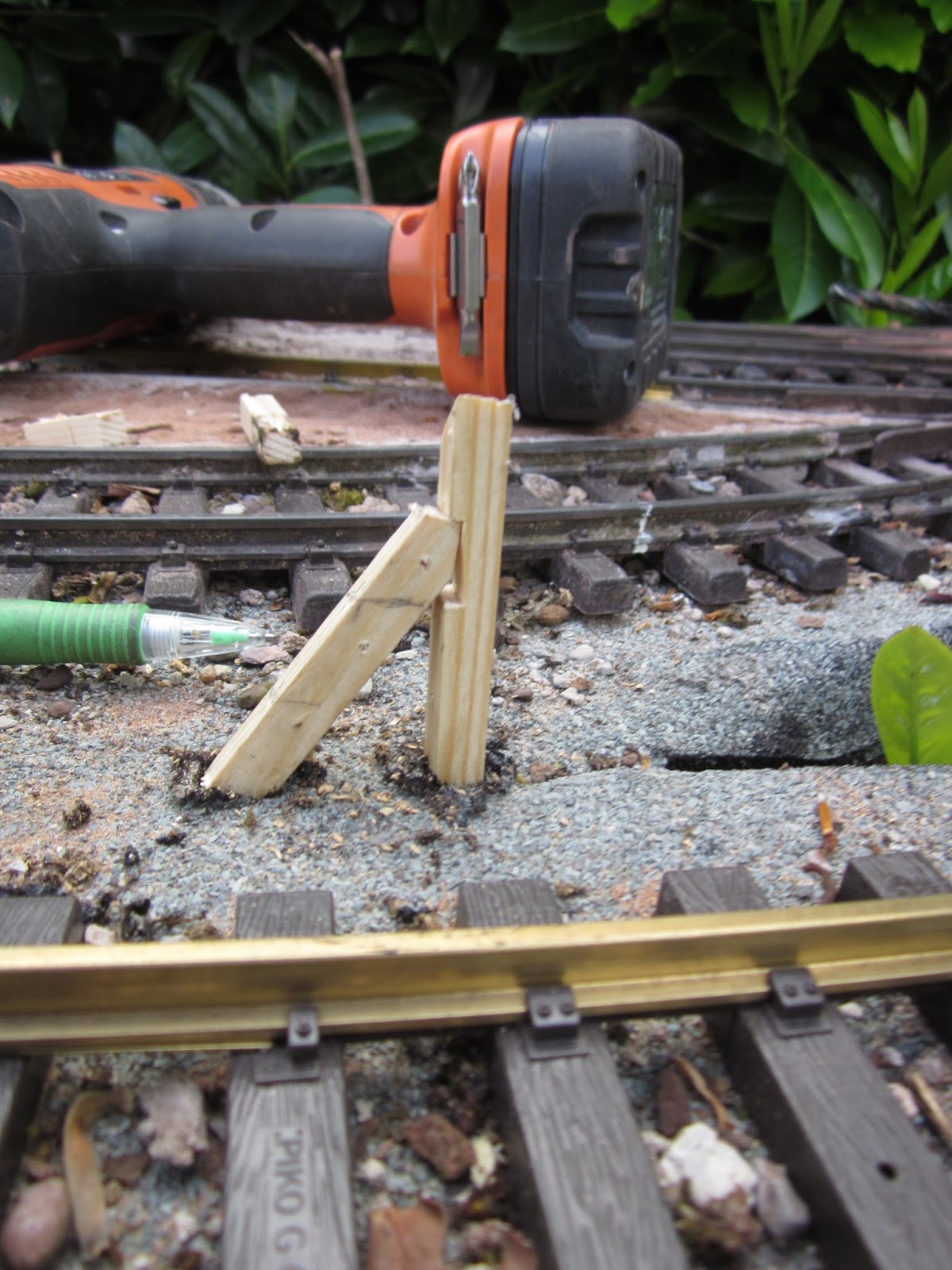
This had been on the to-do list for quite a while. Stripwood posts had been in places for some time but I had never got around to adding the wires. As some of the posts had become broken, I decided to replace them all (with 8mm square stripwood), suitably drilled ........
..... to take thin copper wire.
The posts were then given a couple of liberal coats of wood preservative.
Copper Mine plate girder bridge
Three bridges are needed to carry the 32mm feeder line (see Progress Report 59) and so far just one has been constructed. This was made from a couple of 00 scale Wills vari-girder kits (see How I constructed a girder bridge for the mine feeder railway - pending).
There are still two more bridges to construct. One will be another plate girder but the other will be a short wooden trestle.
Operating sessions
Despite all this construction work, I have managed to fit in some operating sessions. I have not yet managed to work a complete timetable through, but I have run a couple of freight handling sessions and also been able to run some passenger services and the occasional copper ore train.
This video shows extracts from the most complete operating session
While this shows the running of a freight service, one evening when the air was warm and I had an hour or so to spare before settling in the evening.
For me, this is one of the joys of garden railway modelling. I can run full prototypical timetabled sessions or just put a fairly random selection of stock and a loco on the track as the fancy takes me.
Visitation
Finally, I was fortunate enough to host a visit from a fellow garden railway modeller who runs the Deben Valley Light Railway. It seems we have quite a lot in common - we both use 45mm track, our railways depict hypothetical railways in real locations, we both enjoy running goods and passenger services and we both admire the Southwold Railway. One major difference between us is that he greatly enjoys operating with live steam, whereas I am (at present) fully committed to battery electric. Zach brought some of the DVLR stock with him, including one of his live steam locos - an early Merlin 'Little Wonder' loco - River Tang
So, for the first time in the Peckforton Light Railway's history, a live steam loco ran on her metals.
It made me realise that my railway was not constructed with live steam running in mind. I have too many gradients and undulations which I hardly notice when running battery locos (or their forerunners, track-powered locos), but which require very careful driving when operating a live steam loco.
I was also delighted to have a former Compton Down loco constructed by the sadly missed Peter Jones running on my railway.
What on earth is there not to like about this hobby?
Quite a lot has happened since the last progress report. I have finished the ex-Davington Light Railway Manning Wardle 0-6-0ST and played host to a fellow modeller from Australia. I have also made a start on bashing a trio of Bachmann Jackson Sharp coaches into something vaguely resembling the balconied stock which ran on the Leek & Manifold Valley Light Railway. In addition, I have been experimenting with different forms of battery power, partly because the space inside the Manning Wardle was quite restricted. Finally, I have had a go at re-organising the storage in my workshop as things in there were becoming increasingly cluttered - and also I am starting to batten down the hatches in preparation for the onset of winter.
Manning Wardle 0-6-0ST
After a few trials and tribulations, I have at last completed the scratchbuild of my latest loco - an 0-6-0 saddle tank based (loosely) on those which Manning Wardle produced to run on the Davington Light Railway.
As this railway closed shortly after the end of World War I, I reasoned that one of the three locos was sold to the Peckforton Light Railway - the other two finding their way to Brazil (see How I constructed a Manning Wardle 0-6-0ST locomotive).
Although I have previously scratchbuilt three locomotives, made two from kits and kit-bashed a railbus, I found this particular build to be more demanding than any of the previous builds. This was partly because the extra work involved in making the saddle tank proved trickier than I expected, and also because I ran into a couple of unexpected snags along the way: the Revell filler which I used initially refused to adhere to the plasticard and was susceptible to cracking, and I discovered to my dismay that Evostik is an extremely powerful solvent of plasticard (see How I constructed a Manning Wardle 0-6-0ST locomotive).
Despite these trials and tribulations, I am very pleased with the end-result. Not only does she look quite appealing, I have discovered that the six-coupled wheelbase is extremely powerful when it comes to hauling excessive loads up my 1:40 gradients on the railway.
Here's a video of the loco's first run on the railway (before I had finished all the detailing).
An this video shows her phenomenal hauling capabilities. I certainly did not expect her to be quite so powerful.
I have been really impressed with this loco's slow-running abilities and her responsiveness to the Deltang receiver/controller. Given this and her hauling capability, I anticipate she will become the preferred loco for freight duties on the railway.
Running sessions
With the mild weather in September and the early part of October, there has been plenty of opportunity for me to run trains out in the garden. A few shots taken during one of the operating sessions to show how the railway and its stock are developing.......
Wynford sets off with a train of full ore wagons from the copper mine sidings
She traverses the recently relaid track on the approach to Beeston Castle.
At Beeston Castle, Loco No. 4 Bulkeley (former Southwold No. 4 Wenhaston) passes with the mid morning Down passenger train
The mid-morning Down passenger approaches Bulkeley as the Down pick-up goods approaches Beeston Market
The Down pickup goods coasting beside the River Gowy on the approach to Peckforton with Loco No.5 Tarporley
The Down pick-up goods leaving Peckforton and approaching the mill siding where she will exchange wagons
The Down pickup goods pulls into Bulkeley as the noontime Up passenger waits to depart.
The noontime Up passenger arrives as Beeston Market
The mid afternoon passenger about to depart Beeston Market as the Up pickup goods arrives
Meanwhile, skips are shunted at the Copper Mine.
Australian visitor
For some time, I've been corresponding with a fellow modeller in Australia, mostly picking his brains on radio control and how to wire up and program Picaxe microchips for the operation of signals and pointwork (see Progress Reports 52 and 53). The website for Greg's own garden railway, The Sandstone and Termite, is packed with useful information and ideas and well worth a visit. When he expressed a desire to revisit the UK to travel on the Welsh narrow gauge railways, I offered my services as a local guide. Earlier this month, Greg and Pauline came over for a couple of weeks and spent around a week exploring the locality of Cheshire and another week in Wales. He risked x-ray machines and border controls to bring one of his locos with him, Nick, a freelance railbus. Over the course of his visit we found time for three running sessions as the weather was particularly kind to us.
Sandstone & Termite Railway railcar Nick shunting at Beeston Market
Nick makes an inaugural run down the line, past the Copper Mine
Old and new railbuses are compared at Peckforton
Nick braves the undergrowth between Bulkeley and Peckforton
On light freight duties beside the River Gowy
Beside the Gowy on passenger duties
The two railcars on night duties at Bulkeley station
Greg was pleasantly surprised to find that the weather in the UK in October can actually sometimes be clement. Here we see our esteemed visitor, sporting his Sandstone & Termite Railway tee-shirt, assuming responsibilities as Chief Controller at Beeston Market.
Despite a few early teething troubles, everything on the railway performed well. I'm sure there is a Law of Garden Railway Modelling which says that the moment a visitor arrives, anything that can go wrong will go wrong - and for a while this seemed to be the case. Thankfully, this did not persist for the entire two weeks!
Bachmann Jackson Sharp to Leek & Manifold(ish) coach bash
The passenger coaches which the line presently possesses (see How I constructed coaches from Maddison kits) perform their function very well and although there are only three, this mirrors the level of coaching stock for many narrow gauge railways in the UK (see How much stock did UK narrow gauge railways have?). However, to enhance the railway's operational potential, I have for a while considered acquiring at least another three coaches to allow two passenger trains to operate at times of additional demand (eg market days, special excursion trains). Before constructing the Maddision coaches, I used to run a couple of Bachmann Jackson Sharp balconied coaches which, despite their smaller scale, represented for me something vaguely resembling the stock used by the Leek & Manifold and the Southwold Railways(seeProgress Report 11)
A passenger train on the railway in 2008
For at least five years these coaches have languished in a drawer in my workshop until I came across some drawings of the L&M coaches and did a few quick calculations. I realised that I could produce a foreshortened representation of these coaches if I narrowed the windows slightly and lengthened the balconies a little.
The bodies needed to be increased slightly in height but as the clerestories were going to be removed this would not actually increase their overall height. I already know that these coaches have no problem tackling the tight curves on my railway and so have pressed ahead with the 'modification' of the first coach.
I am presently about halfway through bashing this coach and am using this as a learning-curve for bashing the other two. Two coaches will be opens and the other will be a brake end.
Battery power
Although I am relatively new to the world of battery power and radio control I have already accumulated a fair amount of experience in constructing battery powered locomotives and experimenting with various combinations of radio control devices (see An Introduction to battery power and radio control). Given their power-to-weight ratio, I am now convinced that li-ion batteries are the most cost effective and efficient way of powering garden railway locomotives. There are some risks associated with this form of technology (as witnessed by recent fires aboard aircraft and the occasional horror story about mobile phones bursting into flames), but given that most portable technology is now powered by li-ion batteries (including the laptop computer on which I am writing this blog), it would seem that the vast majority of li-ion batteries are sufficiently reliable to be considered for this application. However, I still have a couple of locos which are powered by NiMh batteries but have recognised that there are better options than normal off-the-shelf rechargeable batteries.
18650 Li-ion
As mentioned above, one of the difficulties I encountered with modelling
the Manning Wardle saddle tank loco (see How I constructed a Manning Wardle 0-6-0ST loco) was finding room inside for the
batteries. My usual source of power; the 12v blue lithium-ion batteries
intended for CCTV applications (seeAn Introduction to Battery Power and radio control)
were too large to fit into the confined space ......
........ and there was no way I
would have been able to squeeze ten NiHh 1.2v AA (or even AAA) batteries
in. After discussing various options with fellow modellers on the G Scale Central forum, I invested in some 18650 style 3.7v li-ion batteries. These cylindrical batteries are what many laptop computers use inside their battery packs and so there is a ready supply and a wide variety of types available. However, even in my limited experience, I have learned that you do tend to get what you pay for. Some of the cheaper, so-called high capacity 18650 batteries do not live up to expectations. The first set of these batteries I bought for a modest sum claimed to be 5000mAh (ie they would power a motor running at 1amp (ie 1000mA) for five hours.
When I did a discharge test on them, they averaged-out at 1.5Ah (ie 1500mAh) - considerably lower than that claimed. I then opted for some more expensive, branded (Samsung), batteries from a reputable supplier. These were labelled as 3100mAh and when tested were not far short of that capacity.
Another aspect which I have appreciated needs to be taken into account is whether the batteries are 'protected'. Li-ion batteries can be damaged, or worse still can catch fire, if they are under- or over-charged. To ensure this doesn't happen, protected batteries include a small circuit board which cuts off the charge or stops the battery from discharging if the voltages fall outside the accepted safe levels. The 18650 batteries I am using in my latest loco are unprotected and so I make sure that I charge them carefully using a balance charger and regularly check their discharge with a small battery checker.
This plugs into the balance charge socket and the LEDs show green if the batteries are OK and turn to red (and the buzzer sounds) if they drop below 3.3v. When running, I leave it attached to my loco but remove it when I store the loco.
NiMh low self-discharge
One of the most irritating aspects of normal NiMh rechargeable batteries is the speed with which they lose their charge when not being used. Many's the time I've wanted to have a quick impromptu operating session and been unable to use the locos powered by NiMh batteries because they've needed charging. My Australian friend alerted me to low selfdischarge NiMh AA batteries which can be obtained from Hobbyking for quite reasonable prices.
These batteries seem to be holding their charge very well. I've detected very little drop in power even after a loco has been in storage for a couple of weeks.
Workshop revamp
Partly inspired by the arrival of my house guest from the colonies, I felt it was time to re-organise the storage in my workshop. Some of the odds and ends which I had accumulated had outgrown the space allotted to them and there were times when I struggled to lay hands on a material or component needed during construction. I had previously organised some of my tools by fashioning a rack .......
...... and so now invested in some storage containers from our local pound shop ..........
...... and constructed a storage unit for larger and longer materials.
Previously, trying to use the conservatory for its intended purpose of sitting, chatting and admiring the garden had not been a pleasant experience. Now it is at least possible.
Preparing for winter
The station buildings have now been brought inside. Previously I had left these out throughout the year but at the start of this year I had realised how dilapidated they had become.
After spending some time re-gluing and repainting them (see Progress Report 52), I decided this was one job which could be avoided, or at least postponed, by storing the buildings inside during the worst weather. If I do need to have some buildings in place during the winter, to take pictures or video, then it takes only a few minutes to re-install them.
To Do List
There is always something which needs to be done on a garden railway - which is really what makes the hobby so interesting. My present and ongoing list comprises:
 Having previously constructed a Manning Wardle 0-6-0 locomotive using a Piko motor block (see How I constructed a Manning Wardle 0-6-0T loco), I decided it was about time I provided her with sound. As with three of my locos, I invested in a MyLocoSound steam soundcard. The more recent Universal card is not only adjusted using an infra red remote control rather than using onboard preset potentiometers, it includes sound effects in addition to the conventional steam whistle. These effects include a guard's whistle, a bell (or short steam whistle), the sound of a safety valve blowing off and an air pump. The effects can be triggered by the remote control or through a receiver and transmitter with the requisite number of spare channels.