Showing posts with label coaches. Show all posts

Tuesday, February 22, 2022

Progress Report 94

Well! I can't believe my last progress report was three months ago! In many ways, so much, and yet so little, has happened. 

At this time of year, most of my modelling is indoor, rather than braving the elements outside on the garden. As mentioned in my previous progress report, I have become interested in creating an indoor representation of the Glyn Valley Tramway (GVT) in 7mm scale. Quite apart from the fact that the site of the GVT is less than an hour's drive from here, I have always been fascinated by its rolling stock and its rationale - serving the slate mines and granite quarries in the picturesque valley of the Ceiriog Valley.
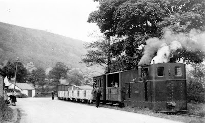
Source: NGRS WJK Davies Collection

To this end, I have now created not only one of the locomotives but also two styles of coaches, a van, a guard's van and an open wagon. These have been 3D drawn in TinkerCAD and several copies printed out on my 3D printer.

 In addition, I have completed another instalment in my video history of the PLR and created another video explaining what prompted me to create a garden railway.

Other than that, my productive output has been limited to tinkering and tweaking. There is always something to do on a garden railway and, of course, in the garden and house.


The Glyn Valley Tramway project

Whether it's my imagination or an effect of climate change, our winter weather seems to be changing. We have fewer frosty mornings but we seem to have a lot more wind and rain. Those latter conditions are not ideal for running a garden railway. In the past, I have usually managed to organise some partial running sessions during the winter months, but this year fewer opportunities seem to have arisen. This has prompted me to explore the setting-up of an indoor line in the workshop. Rather than G Scale, or 16mm scale, I decided to venture into 0-16.5 scale (ie 7mm (0) scale models running on 16.5mm gauge track). This equates to roughly 2' 4" gauge which is what the Glyn Valley Tramway used.

There is plenty of information online about this delightful railway which was ostensibly built to transport output from the granite and slate quarries around Glyn Ceiriog to the canal and mainline railway at Chirk. I have always been attracted by the four wheeled coaches and compact locomotives which ran on this railway, but a further attraction is that Chirk is around an hour's drive from where I live.
Source: NGRS Collection

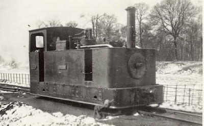
Locomotive "Glyn"

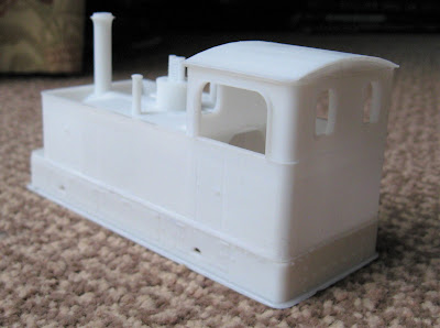
I decided to start by constructing one of the line's three Beyer Peacock locomotives and opted for the slightly larger version named Glyn.
I figured out how the loco could be broken down into segments suitable for 3D printing and then drew the respective parts using TinkerCAD - a freebie online 3D drawing package which I have found to be the easiest to use of all those I've tried.
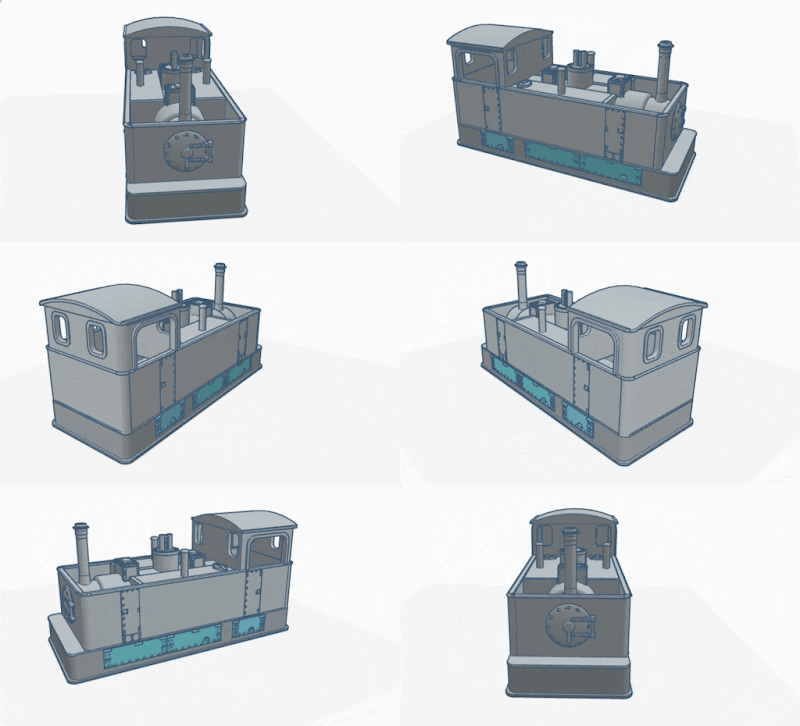
The parts were then printed out using my recently acquired resin printer and glued together.
The body was made to fit on a Hornby Smokey Joe 0-4-0 chassis ......
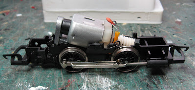

 and so a two wheel bogie (or more accurately a pony truck, as the locos always ran cab-first) was also designed, drawn and printed-out. 


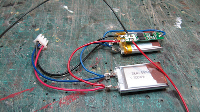
The electrics were then wired-up, using two mobile phone lipo cells and a Deltang Rx60 receiver/controller for radio control.
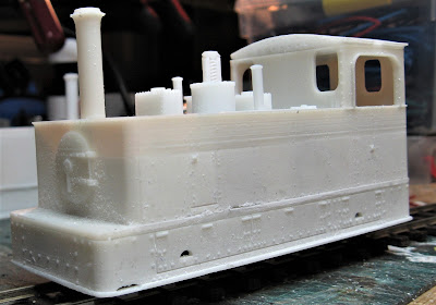
The loco is awaiting a coat or two of paint and finer detailing.

Coaches

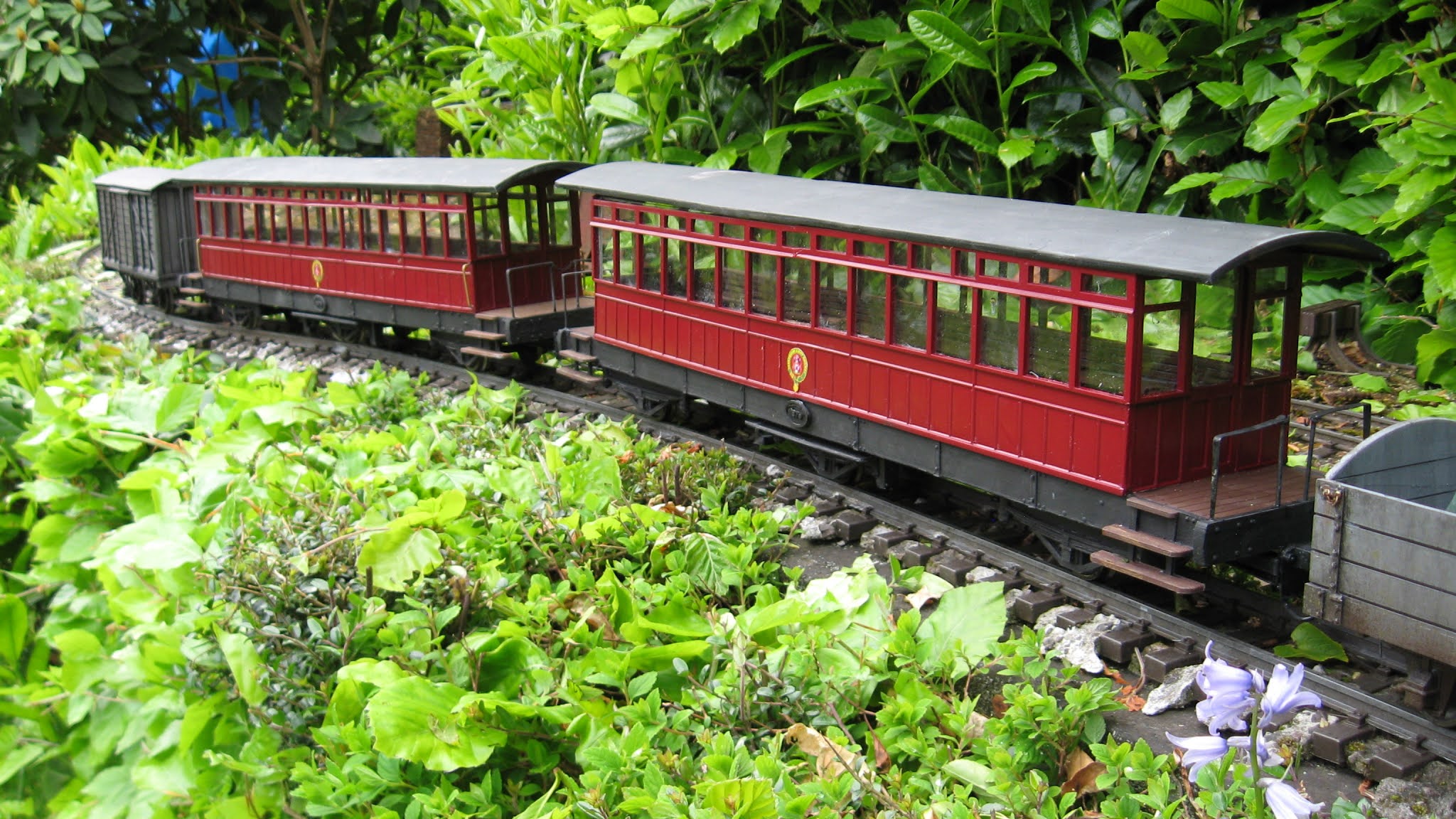
So far, two designs of coaches have been drawn, printed and constructed; a closed third .....
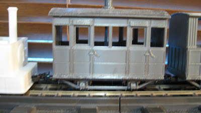
..... and an open coach.
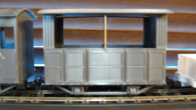
I will eventually produce all the coach variants which ran on the railway.


Goods stock

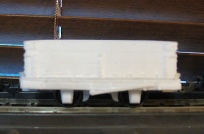
Up to now, the line's distinctive style of granite wagon has been drawn and printed .....
.... and a brake van.
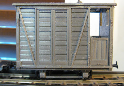
Next on the agenda are slate wagons, vans and flat wagons.
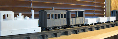

When I have finished drawing, printing and constructing the stock I need in 0-16.5 scale. I will probably re-scale the drawings for 15mm or 16mm scale. I quite like idea of having a rake of GVT coaches running on the PLR. 

Eventually, the .STL files will be made available as downloads on Thingiverse.

The track plan

I haven't finalised a trackplan for the railway as yet. I might keep it very simple and just have a passing loop such as that provided at Pontfaedog. Alternatively, I might opt for a simplified version of the Chirk terminus and somehow include a complete circuit of track.

I'm also trying to figure out if I can somehow also retain the 45mm test track which I completed last year - see How I made a test track in the workshop


History of the Railway Part 5

Having put together four previous videos charting the history of the PLR, I have now brought the story up to date by making another video showing what has happened on the railway over the past year.


I will now continue this practice of making another video at the end of each year. They say a garden railway is never entirely finished and so it is likely there will be another few years' worth of video histories yet to come ....

<< Previous Progress Report                         Next Progress Report >>

Saturday, June 05, 2021

Progress Report 91

According to the meteorologists, May was one of the wettest since records began - and it felt like one of the coldest. However, the weather turned completely during the last weekend of the month and I was able to have a full running session which gave an opportunity to test out a few of the projects I had been working on during the bad weather.


Infrastructure

 Fencing

Owing to the poor weather, I was unable to do much out in the garden. However, following a tip-off from a fellow GardenRails forumite, I bought a few lengths of Fairy Garden fencing from eBay.

I hadn't seen it before, but I was told it's been around for a few years now but it seems good value for a 90cm length of fencing in the right scale. The palings are thin wood (similar to coffee stirrers) and they are held together with twisted plastic coated wire. This means the fencing is very flexible in both the horizontal and vertical planes.


Level crossing

 The first application of the fencing has been alongside the level crossing on the approach to Peckforton station.

To fix the fencing in place, I added some copper wire stripped from 13A twin and earth electrical cable. This was forced in behind the twisted wire of the fencing at roughly six inch (15cm) intervals and secured with a couple of bends, leaving a tail of around an inch (2.5cm) pointing downwards.

The tail ends of the copper wire brackets were then inserted into plastic rawlplugs forced into holes in the concrete breeze blocks which form the trackbed.


 Permanent way

Remote point operation

A couple of hard to reach points (turnouts) at Beeston Market and Beeston Castle stations have had push-pull point rodding added, using galvanised fencing wire and screw eyelets.


In addition, the two points for the storage sidings in the lean to can now be operated remotely from the entrance to the sidings with twist point rodding. 

For more information see Operating points remotely using simple point rodding


Stock

Double diesel

The double ended diesel loco which I 3D printed has now had its dummy trailer loco motorised.

It already had a 3D printed chassis which was designed to accept a motor and worm gear set from IP Engineering and so it was a quick and easy conversion. Four wheel drive was also added with Delrin chain and sprockets. 

 Although the locos are powered with cheap three volt can motors, the loco is now quite powerful coping easily with a train of eight loaded hopper wagons and a brake van up the 1:40 gradients on the railway.

In addition, the locos have been given name and number plates, drawn in TinkerCAD, 3D printed and painted. 

The names, Dorothy and Diana, as well as being alliterative with Double Diesel, are taken from two of the daughters of Lord Tollemache, the supposed benefactor of the Peckforton Light Railway.


Schull & Skibbereen loco

 The motorisation of the 3D printed Schull and Skibbereen loco (see How I drew and 3D printed a Schull & Skibbereen loco) is still being worked on. The original Bachmann Lyn motor block proved to be under-powered and so I have been seeking ways of improving its mechanical efficiency.  Initially, the difficulty was finding smaller diameter worm gears which were compatible with the original worm wheels. I tried using different gear sets but they weren't sufficiently robust. I then discovered that the worm gears on Bachmann motor blocks are fairly interchangeable and so I am presently redesigning the motor block to make use of the worm gears from another Bachmann loco.

Getting the gears to mesh reliably and smoothly is proving to be very difficult inside a fully enclosed motor block housing. 

However, I will not be defeated!


Second SR coach

 After developing the design of the Southwold six wheeled coach, I have now constructed a second one.

I discovered during a test run, that the centre truck kept derailing. Closer examination revealed that the arms of the swivelling mechanism on the outer trucks were 4mm too short. Not sure how this happened when I redesigned the trucks, but it just emphasises how critical the dimensions need to be.


A third coach should hopefully finalise the design.


 Cleminson open weathered

The six wheeled Southwold open wagon has now been weathered

I have now used the wagon twice on operating sessions and, touch wood, it seems to be performing well. It did derail on one of the points at Bickerton Station, but hopefully this will not be a regular occurrence.


Operation

Running session

Although the weather has generally been bad through May, it improved markedly towards the end of the month and so I managed to organise a full running session.


Using the Psion

During the running session, I made good use of my Psion pocket computer to manage the freight handling (see How I programmed my Psion 3a pocket computer for freight management).

I am very pleased with how my revisions to the original program performed. At the start of the session, the location of some stock didn't match where it was supposed to be according to the program. This is because through May, I had been having ad hoc running sessions and testing locos and new rolling stock and so the wagons had become displaced.

I found that the easiest way to change a piece of stock's location in the database was firstly to reset all wagons to Beeston Market and then use the List and Move functions to relocate stock which had found its way to other stations. 

<<< Previous Progress Report              Next Progress Report >>>


Sunday, May 21, 2017

How I installed lighting in my coaches


Introduction

 Having just finished detailing the interiors of my Leek and Manifold Railway (ish) coaches (see How I made interiors for my coaches) and modified some figures to sit inside them (see How I modified some cheap figures for the 1930s), I thought it might be opportune to install some lighting in them. I thought of various ways it could be done such as using a bus-bar as I had done on my Ford(ish) railcar (see How I bashed some Andel coaches into a railcar). However, some time ago I had bought some lighting boards cheaply on eBay which were supposed to work off track power, so I decided to use these as the basis for my lighting circuitry.


Preparing the lighting strips

The first job was to remove all the components from the perforated boards. For some reason, the LEDs were wired in series and so, as I wanted to run them from a 3v supply, I needed to rewire them. The components (ie rectifier, voltage regulator, capacitor) were redundant and so were relegated to the spares box.


The LEDs were wired in parallel and trailing leads added to one end.


I now needed to decide on which batteries I would use and how the lighting would be switched on and off

Batteries and switches

Option 1 - Alkaline batteries and manual switch

My first idea was to keep things very simple. Power the lights with two AAA alkaline batteries and switch them on and off with a latching push-button switch.

The lighting strips were fixed under the roof with BluTak and the switch contacts were soldered directly to the contacts on the battery box.

The battery box was then attached to the underside of the roof with BluTak.

NOTE: Subsequently, I discovered that when the sun shone (a rare occurrence in this part of the world), the BluTak softened and was insufficient to hold the battery box in place, and so the BluTak was replaced with Gaffa Tape.

Of course, this meant the roof had to be removed each time I wanted to turn the lights on or off, but it also meant that, as all the wiring was attached only to the roof section, there were no trailing wires between the roof and the rest of the coach body.

However,I was not entirely happy with this arrangement. Although I fixed the rood in place with magnets to make it easily removable, I wanted some way of turning the lights on and off without having to remove the roof each time. The magnets gave me an idea.


Option 2 - Latching reed switch and alkaline batteries

As I did not want the switch to be visible on the roof, and I didn't want wires leading down from the roof to the body of the coach, I needed a method of operating the lights remotely. Radio control was an option, but expensive, whereas reed switches could be triggered with a magnet. However, reed switches only provide momentary switching so I searched the internet for simple electronic circuit which would provide latching on/off switching. There were some available, but these were quite complicated affairs - I much prefer the simple (and cheap!).

My mate, Greg, in Australia drew my attention to some very cheap electronic modules which provided latching outputs from a momentary trigger.

At just over £1.00 each (including postage), they were a lot cheaper than I could make from discrete components - and so I sent off for a few.

There were other versions available and I also considered latching Hall Effect integrated circuit chips, but the residual current drain (ie how much current they consume when 'off') was 60uA, whereas the residual current drain on these modules is 'less than 2uA, according the blurb on the eBay page.

When they arrived (by slow boat, it seemed), I wired one up on a small piece of Veroboard with a reed switch connected between the 0v and Trigger inputs.

This was then connected to the battery box and the lights.

The wiring is minimal - the Veroboard is not essential but, as reed switches are very delicate, I wanted to provide some sort of protection against accidental damage.


In the coaches, there are six LEDs wired in parallel, but these have been omitted for clarity.

Option 3 - Magnetically operated switch with a 3.7v rechargeable li-ion cell

For the third (brake end) coach, I decided to explore the feasibility of using a rechargeable 3.7v li-ion cell. I made up a small circuit board as above, but included a 2A polyswitch to protect against accidental sort circuits.

This was wired-in between the positive lead from the li-ion cell and the +ve input leg of the flip flip module.

However, I realised I also needed to include a 1S li-ion battery protection board in the circuit, to protect the li-ion battery from becoming over-discharged. Li-ion batteries must never fall below a charge of 2.7v otherwise they become permanently damaged and so some form of electronic protection needs to be included to prevent this from happening.
 
A 1S protection board was acquired (via eBay) and wired-up - two leads to the li-ion cell and two leads to the flop flop module board.

The cell and protection board were then wired-up with the module and LED boards.

Once everything had been tested, I made a box for the li-ion cell from black 1.5mm plasticard .....

 A 2.1mm DC socket was included in one end of the box ........

 ...... and wired-up .......

....... so it could be used to recharge the battery. All the leads and the battery protection circuit board were shrouded in heatshrink sleeving to help avoid accidental short circuits.

The battery box was assembled .......

...... and then wired back into the main circuit,

The battery box was fixed beneath the floor of the coach ......

 ..... giving plenty of clearance between it and the track.


....... and the leads from it connected to the rest of the circuitry with a 2 pole micro JST connector ......

..... enabling the roof to be removed completely if the need should arise.

Conclusion

In all three coaches, the lights are now switched on and off by waving a magnet over the coach roofs.

The reed switches have proven to be very sensitive and the magnet needs only to be waved in its general vicinity for the lights to come on (see video below).

I may increase the value of the resistor in the LED circuits, to reduce the current to the lamps. In the dark, they seem to be a lot brighter than the lighting which would have been available in the original coaches. This will have the added advantage of increasing the 'life' of the batteries before needing replacement or recharging.

I will be interested to find out how long the batteries do last. I imagine they will last longer than a year given that the current drain on them is so low. However, field-testing will enable me to put a more definitive figure on that. In the meantime, I am very pleased with how the coaches look - I now need to consider ways of lighting the station buildings and platforms as I now have good reason to run night trains.