After building the extension to
Beeston Market and the
Copper Mine (see
How I constructed the extension), the
Copper Mine Sidings were used without any kind of buildings for a couple of years, but it was always my intention to provide some sort of backdrop giving the impression of the mining infrastructure.
As the sidings are built into the hedge bordering the garden, there was limited space and so I opted for a set of low-relief buildings. I had already constructed a wooden loading hopper from a kit which I had acquired through
eBay (see
How I constructed a loading hopper) and so this was used as the starting point.
Planning
After searching various sources for inspiration, I stumbled across Ian Peaty's
Moving Mountains by Rail (2006), which includes several useful photos of quarry and mine buildings. The one on the lower section of the cover proved most interesting to me. This turned out to be a photo of
Penderyn Quarry near
Aberdare in South Wales.
Drawing upon the images in the book, I drafted some sketches of the buildings which I felt would be appropriate. I divided the buildings into three sections: the crusher shed and waste loading chutes plus manager's office:
...... the conveyor for loading the crushed ore into the loading hopper:
....... and the messroom and workshop:
I decided the buildings would also provide me with an opportunity to experiment with a range of building techniques.
I had already gained ideas and inspiration from Peter and Kes Jones' excellent book,
Making Model Buildings for Garden Railways (2011) and so I was ready to start construction.
The foundations
Having a stock of 12mm exterior plywood to hand, I used this for the framework. The rear outline of the buildings was marked on to the ply and then cut out with a powered jigsaw.
The side walls were then added, using various widths of 1" (24mm) thick timber to provide some variation in the depth of buildings. The manager's office was given no additional thickness as it was assumed this would stand back slightly from the other buildings.
Next, the front walls and roofs were added, using 6mm thick exterior ply.
The structures were then given a couple of liberal coats of wood preservative.
Next came the stage where I clad the frames with suitable materials to represent timber, corrugated iron, dressed stonework and coarse stonework.
Cladding - timber
A box of 1000 wooden coffee stirrers was purchased via a well known online auction site. These were squared off with a pair of scissors and then glued to the plywood base with exterior grade PVA.
The joints on the rows were staggered to give a more realistic finish and gaps of around 1mm were left between the 'planks' to exaggerate the distinction between the boards.
Once the front and sides of the base had been clad, the upper surface was planked with lollypop sticks. These were thicker and wider than the coffee stirrers to give the impression of more substantial timber work.
These were cut to be wider than the shelf to provide a 40mm overhang.
Cladding - Corrugated iron
From the book, it was clear that many buildings on quarry and mining sites were constructed from the ubiquitous corrugated iron sheeting. I managed to source two supplies of large-scale embossed corrugated iron plastic sheeting -
Back2Bay6 (now unfortunately no longer trading since the untimely death of its owner, Steve Warrington), and from
eBay (after a search for
G Scale corrugated plastic sheet).
The sheets were cut into 'sheets' of around 45mm x 100mm and then glued into place on the base with
Wickes Instant Grab adhesive.
Initially, I opted for a tube of their '
solvent free' adhesive as I figured
the solvent might attack the plastic, but when I went back subsequently
for another tube, there was only '
solvented' available - which turned
out to be fine (and didn't attack the plastic). Strips of uPVC trim (off-cuts from the swing bridge - see
How I constructed a swing bridge from uPVC trim) were then glued into place to act as eaves and to tidy up the edges of the buildings.
Although the adhesive claimed to be 'instant grab' and was glutinous enough to fill the corrugations, I left the buildings for 24 hours to make sure the adhesive was fully hardened.
Inevitably, I ran out of plastic sheeting and so when it came to cladding the roof of the mess room, I resorted to another approach. A thick foil baking tray was flattened out and smoothed as much as possible.
This was passed through a paper corrugator (again bought from
eBay).
The corrugated foil was then cut into sheets, roughly 45mm x 100mm .......
...... and glued to the roof of the mess room with
Instant Grab adhesive.
Cladding - dressed stone
Yorkshire stone slips were bought through
eBay. I think these are intended for dolls house construction but they seemed ideal for the stonework on the manager's house and the base of the workshop. They were glued in staggered rows using exterior PVA.
As with the timber cladding, gaps of around 1-2mm were left between the blocks to represent the mortar courses and to exaggerate the stonework effect.
Lintels were cut from 3mm thick balsa wood for the manager's house.
....... and the frames for the windows (from
Jackson's Miniatures) were fitted into place during the gluing to ensure there would be sufficient space for them.
Cladding - Random stone
I decided the mess room alongside the workshop would have been constructed from random stone blocks - possibly thrown together by the workers using waste material from the mine. The blocks were roughly cut from 4mm thick balsa wood and then smoothed with fine sand paper. They were then glued into place using exterior PVA.
Stonework - grouting
Once all the stonework had been glued and the glue had set, some cream coloured tile grout was mixed to a thick paste and smeared over the stonework.
A rubber tiling squeegee was pushed and pulled diagonally across the blocks to ensure the grout flowed into all the mortar courses.
The excess was then wiped off with a damp sponge to leave the stonework proud of the mortar courses.
Detailing
Canopy
The framework for canopy over the feeder line for the crushing shed was constructed from 8mm square section stripwood.
The 120mm long cross-members were mortised ........
..... to fit into slots which were cut into lateral beams, with cross members 95mm apart.
The slots being cut using a razor saw and chiseled out with a craft-knife blade
A piece of 8mm square stripwood was glued beneath the overhang of the balcony with exterior PVA.
The cross-members were glued into place in their relevant slots.
The frame and its supports were not fitted into place until after the corrugated iron cladding had been painted (see below). Corrugated plastic sheeting from
Jackson's Miniatures was used for the roofing material as this resembled asbestos sheeting.
Loading chutes
I decided these would be made from coffee stirrers as I had seen some wooden loading chutes constructed in this way in photos on the internet. They had also been lined with steel sheeting which I felt could be added later.
Card templates were cut out, to ensure the geometry would be correct and also to make sure the chutes would fit into the spaces between the supports for the awning.
Masking tape was then stuck down to the workbench, with sticky side facing upwards.
Trimmed coffee stirrers were then stuck to the masking tape
..... and the template placed over to enable the outline to be marked.
The centre-line was also marked.
Suitably trimmed coffee stirrers were then glued into place with PVA.
The 20mm high sides of the chutes were similarly constructed.
and when the glue had set, the base and the two sides were glued together.At this stage, I realised the chutes needed to be pared down to ensure they didn't foul the roof of the loco as it passed beneath. The chutes were trimmed to 50mm depth, 100mm wide at the top and 75mm wide at the base.
Support struts were cut to length (70mm) from 6mm square stripwood ......
..... and glued into place beneath the balcony, with the sides of the chutes glued to the vertical supports of the canopy. Cross-pieces were cut to size and glued between the struts for extra strength.
Staircase
I felt there should be some means for the workers to reach the balcony externally and so I decided to construct a staircase. The staircase was made from plasticard and 8mm square section Plastruct. The main support beams (100mm high and 75mm wide) were joined with 50mm extensions for the banister rails.
Short (35mm) struts were added ......
and the 90mm cross members were glued into place.
Two more legs were added to form the platform for the landing half way up the staircase.
Plastruct G Scale staircase sections, 150mm and 165mm in length, were added below and above the platform and handrails cut and fitted into place made from 2mm thick plasticard
A small platform was constructed from cocktail sticks, stripwood and coffee stirrers to link the staircase to the balcony.
The staircase was given a couple of coats of grey primer from a Halfords rattle can .......
...... and then painted with dark brown acrylics before being fixed into place after the buildings had been painted (see below).
The trestle
To support the 15" (16.5mm) gauge feeder railway for the crushing shed, three trestles were constructed from 8mm square section stripwood.
The dimensions (185mm high, 110mm wide at the base and 45mm wide at the top) were marked out on paper and the timbers cut exactly to size using this as a template.
For added strength, the uprights were joined to the cross pieces with glue and cocktail stick pegs.
The frameworks supporting the the track were made from 6mm stripwood (45mm wide and 50mm and 67mm long)
These were glued together .....
...... and then covered with slats made from coffee stirrers
Cross members were attached to the uprights, made from coffee stirrers.
And then the track supports and trestles .......
..... were joined together and painted, when conveyor was constructed (another two trestles were constructed when I realised more were needed). The trestles are actually vertical in the photo below- the camera does lie!
The conveyor
For the main structural component of the conveyor, two pieces of 730mm x 10mm uPVC offcuts from the swing bridge (see
How I constructed the swing bridge from uPVC trim) were superglued to a piece of 25mm wide stripwood.
A piece of 6mm square stripwood was then glued along the centre line on one side of the stripwood.
Two further pieces of 6mm square stripwood were then glued along the edges. The stripwood 'beams' were then marked at 25mm intervals ......
..... and semi circular notches were filed on each of the side members, angling down from the outside to the inside.
A piece of 6mm dowel was then cut into 12mm pieces and sanded smooth.
The dowels were then glued into the notches so they angled upwards from the centre. The main support beam for the conveyor was then given a couple of coats of red oxide primer.
Plastruct 'I' beam legs were cut to support the conveyor at the end and the middle (the uppermost height of the conveyor being determined by the height of the loading hopper mentioned at the start of this article.
A 10mm wide strip of damp course plastic was then cut and glued with
Bostik Clear adhesive to the rollers on the main beam. This was held in place with clamps to ensure the belt had a dip along its centre-line.
Once the glue holding the belt had dried, crushed local sandstone was glued to its surface with more
Clear Bostik.
The supports were then given a couple of coats of red oxide primer and the whole structure weathered with black and mucky brown acrylics.
Painting and weathering
Before starting the painting and weathering, I toured the locality looking for examples of sandstone, wood and corrugated iron structures which might give me some inspiration for painting and weathering my buildings.
 |
| Weathered dressed sandstone |
 |
| Dressed sandstone |
 |
| Weathered corrugated iron and wood |
 |
| Weathered corrugated iron |
For more examples of weathering see (
Weathering photo gallery)
Corrugated iron
The corrugated iron sections were firstly given a couple of coats of red oxide primer from a
Halfords rattle can.
This was given a day or so to harden off .......
....... before being given a wash browny black acrylic, making sure the dark streaks ran from top to bottom.
Using the photos as a guide, I then dry-brushed various shades and tones of brown, green, yellow and silver.
Sandstone
The areas of sandstone were first given a mucky wash to tone down the grouting and provide a base for touching up the blocks.
The blocks were then picked-out with varying shades and tints of yellow ochre, burnt sienna, maroon and burnt umber acrylics. I found that a more watery mix was more effective than a thicker mix as this soaked into the blocks.
The random stonework was also painted using the same approach.
Timber
The timber sections were firstly given a liberal coat of dark brown acrylic.
This was then dry-brushed with increasingly lighter shades of grey.....
.... finishing with a very light dry-brushed layer of grey which was almost white, following the grain in the wood.
Fine detailing
The buildings were mounted on strips of 12mm exterior plywood, the width of which was determined by the buildings and their location behind the Copper Mine sidings (once the laurel hedge had been trimmed back).
Once the buildings had been screwed to their bases, the exposed areas of the base were given a coat of PVA and various grades of local sandstone, sand and grit were sprinkled on.
In addition, some piles of rusting scrap metal (plastic off-cuts) were created in some areas.
and pieces torn from a green pan scourer were glued into nooks and crannies where weeds might grow.
Guttering
After doing some research on sources for plastic and metal guttering sections, I decided that their cost was too prohibitive and so looked for an alternative. On eBay, I stumbled across some brass U channel section which is used by those making stained-glass leaded windows for mounting their glass sections. I also bought a few lengths of 5mm brass tube.
About 7mm from the end of the U channel, I cut a couple of slots and then flattened out the brass section.
The flattened section was folded upwards and trimmed off .....
..... then soldered to form and endpiece to the guttering.
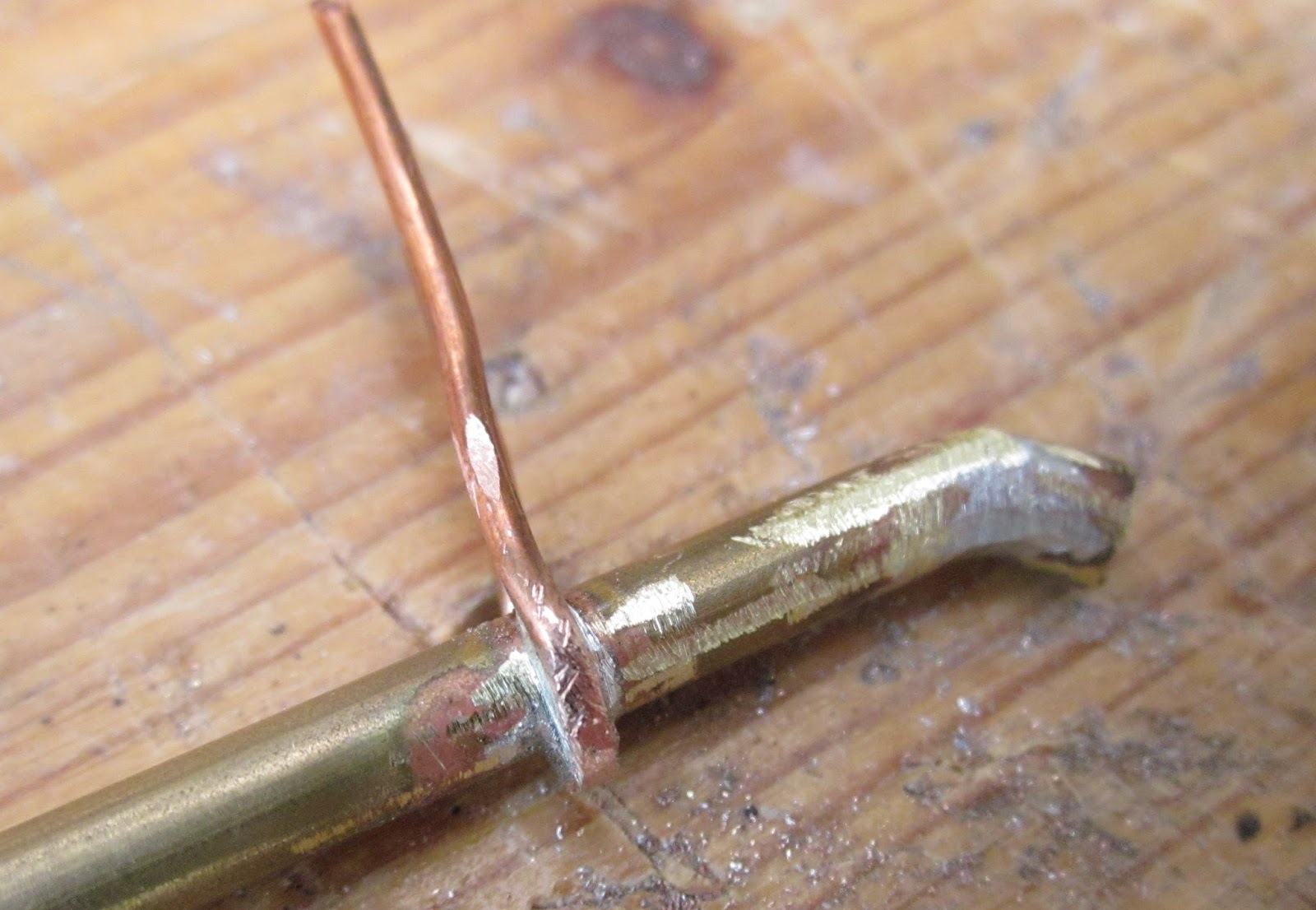
Angle brackets were then folded from copper wire extracted from some twin and earth mains cable.
These were soldered to the front edge and underside of the guttering at 100mm intervals.
The excess was trimmed off the upper edge of the guttering and the front of the copper 'bracket' filed flat.
Holes were drilled along the top of the wall below the roofline at 100mm intervals. After painting the gutters and brackets black, the copper brackets were then inserted into the holes and superglued into place
Copper wire was wrapped around the brass tube at 100mm intervals and soldered into place.
The outer faces of the wire were then filed flat. The bottom of the downspout was sawn halfway through around 10mm from the end, bent forward. soldered and filed clean.
After being painted black, two holes were drilled at 100mm intervals and the copper brackets of the downspout inserted and glued into place with superglue.
Final touches
Originally, I was intending that the copper mines would be served by a Gn15 feeder and so 0-16.5 track was laid on the balcony of the crusher shed.
Two tracks were laid side by side converging into a wye point.
Once the track had been laid, the framework for the canopy was glued into place with uprights extended down to the balcony floor.
The track was weathered and coffee-stirrer planking laid longitudinally over the sleepers.
Earlier this year, the Gn15 track was lifted and rails to a gauge of 32mm were laid, as I decided an SM32 feeder line would be more feasible in the garden.
At the end of the workshop section, a fuel tank was added - recycled from a
Hartland tanker wagon. This was mounted on stone plinths (balsa blocks clad in York stone slips). Oil spills were painted from the cap down the sides and on to the sand covered base.
The
Copper Mine buildings have now been in situ for three years. Despite having been given a couple of coats of matt varnish I am not confident that they would withstand the weather conditions which the North West of England would throw at them and so they are stored in the garage when not in use. It takes less than five minutes to carry them out and position them on the shelf behind the
Copper Mine sidings.
As they are low relief, they are better viewed from the front than from the side.
However, they provide, to my mind, a suitable industrial backdrop to the
Copper Mine sidings and they provided me with experience of different construction techniques.
Since constructing the buildings, the layout of the sidings at the
Copper Mine has changed (see
Progress Report 58). This was partly to eliminate a sharp curve on the mainline but also to provide more space for shunting operations at the sidings.
 |
| The old arrangement of sidings |
 |
| The new arrangement |
....... and, as indicated above, the Gn15 feeder line has been replaced with an SM32 line.
The new trackwork at the mine has been re-ballasted and a newly installed fence separates the sidings from the mainline - as you can see, at least one of the local inhabitants approves....
The new arrangement does indeed give more space for shunting operations and the fencing helps to separate activities going on at the mine from the normal running of the main railway.
There is still more work to be done. The trestles leading up to the
crusher shed need to be rebuilt for the wider gauge track and some of
the detailing around the buildings needs improvement where the new
location of the buildings differs from their previous location. Ultimately, the deliveries of skips from the mine on the SM32 feeder line will be entirely automated (see
How I reprogrammed a Deltang Rx65b for auto-shuttle mode) so that during operating sessions, attention can be paid to running trains on the mainline.


.jpg)