After adding a new siding to Bickerton Station recently (see How I added a siding to Bickerton Station), I was asked for details of the point lever which is connected to the point (turnout) leading the the siding.
These point levers are a fairly recent innovation and are slowly replacing LGB point levers which, until now, have been my default method of operating points manually.
The great advantage of LGB manual point levers is they are fairly robust (they can survive being stepped on) and are spring-loaded and so allow stock to trail through if the point blades are set against them. Their disadvantage is that they do not look particularly realistic.
Mine look reasonably realistic and allow stock to trail through, but don't take kindly to being stepped upon.
They are very easy to construct requiring only a few pieces of brass, some small brass nuts and bolts and a couple of sleepers from a piece of LGB, Piko or Trainline track.
The base
The base comprises two sleepers, removed from a length of plastic sleeper base for straight track.
One end of the two sleepers was removed with a razor saw in line with the web linking the sleepers.
Both webs were left in place at this stage but one will later be removed once the point lever is finished.
The pivot plates
As I was mass-producing levers to eventually replace all the LGB levers, I marked out a piece of 0.036" thick half-hard brass sheet which I had bought from Eileen's Emporium.
The dimensions of the pivot pieces aren't critical but, after some experimentation and various prototypes, I have arrived at the following:
 |
The pivot plate - all dimensions in millimetres (not to scale)
|
The centres of the holes were punched with an automatic centre-punch - I find it's easier to drill the holes before cutting out the individual pivot-plates.
The plates were then cut from the sheet using heavy duty tin-snips.
The bends were then made by putting the plates into a vice, aligning the bend-line with the jaws of the vice, and bashing the protruding part of the plate with a hammer.
One advantage of mass-production is that I was able to match-up pairs of plates - as you have probably noticed, my workshop techniques are more approximate than precise and so sometimes the holes and the bends wander slightly.
The lever
The lever was formed from a 46mm length of 4mm wide x 2mm thick brass strip - once more from Eileen's Emporium.
 |
The lever all dimensions in millimetres (not to scale)
|
Two 2.2mm diameter holes were drilled 4mm and 7mm from one end, and the other end was filed to a curve.
My first early prototype point levers used half-cent Euro coins as balance weights but once my supply (ie that pot on the bookshelf containing all those oddments of change from foreign holidays) became exhausted, I searched eBay and took delivery of fifty 16mm diameter brass disks. Apparently, these are used for jewellery-making.
By the way, as you can see, it pays to shop around as prices can vary widely .......
Four disks were soldered together into two pairs.
My technique for soldering them together was to tin one side of each disk with solder using my 45W soldering iron. The two tinned faces were then placed together and the iron placed in top of the topmost disk until the solder between them melted. The upper disk can be slid about until the two disks are aligned. I find that melting a small amount of solder beneath the iron and the topmost disk helps to transfer the heat more quickly.
The disks were then soldered to the lever, about 7mm from the curved end.
As can be seen, I constructed a simple jig using four brass nails tacked into a piece of plywood around the perimeter of a disk. This helps with the alignment of the disks while soldering - as they have a tendency to slide about once the solder has melted and the disks are a bit too hot to handle!
Of course, there is a 2mm gap between the two sets of weights.
I have tried filling this with solder, but found it was a bit tricky, so I now just use plastic putty filler.
Assembly
With nearly all the parts prepared, it was time for assembly.
One of the pivot plates was placed over the end of the plastic sleeper base, roughly central to the web at the uncut end. A 2.5mm drill bit was then passed through the holes using a mini-drill to create matching holes in the plastic base.
Two 80mm long x 6mm wide x 0.8mm thick brass strips (again from Eileen's Emporium) were then cut.
 |
Two linking strips cut from 0.8mm thick brass.
|
One of these linking strips was then inserted into the hollow underside of the drilled sleeper and slid up to the closed.end. The position of two holes were then marked on the strip using a scriber and 2.5mm diameter holes drilled in the strip.
Two M2 brass bolts were then passed through the holes and nuts tightened on to them.
NOTE: The M2 cheesehead brass bolts from Eileen's Emporium are 12mm in length. I needed to cut them in half. My method for this was to thread a nut on to the bolt, place the end of the bolt in a vice, cut the bolt in half with a slitting disk in a mini-drill, tidy up the cut end of the bolt with a file and then remove the nut which helps to tidy up the thread.
NOTE2: It has since occurred to me that if the bolts are passed through from the underside and the nuts tightened on the top surface of the pivot plate, the nut will look more realistic than the cheeseheads on the bolts.
The lever and the second pivot plate were then loosely connected to the first plate with a piece of 2mm diameter brass rod, sandwiching the lever between them.
The rod was then cut to length using a slitting disk in the mini-drill.
You'll have noticed, I try to avoid measuring where I can - most of my bodgelling is done by eye. My apologies to those with a mechanical engineering background (eg my brother) who are probably shuddering and reaching for their micrometers at this point.

Two 2.5mm holes were then drilled in the plastic sleeper using the holes in the pivot plate as a guide.
As previously, the linking-strip was placed inside the the underside of the sleeper and the position of the holes marked and 2.5mm holes drilled.
The second pivot plate was then bolted into place.
The 2mm rod for the pivot was then soldered into place.
I used my humble 45W soldering iron for this despite the fact that its heat was quickly dissipated and hence it was difficult to get the solder to flow. I didn't want to risk melting the solder holding the balance weights on the lever by using my 75W iron.
Once the solder had set, the excess was filed off,

The web linking the two sleepers ..........

.... was then removed with a razor saw, Allowing the lever to swing freely.

The point lever assembly was now offered up to the point with the ends of the linking strips being slid into the sleepers on either side of the tie bar (you may need to open up the ends of the sleepers on your points). The position of the holes in the turnout's sleepers were marked on to the linking-strips (or drill new holes if your point doesn't already have them).
Two 2.5mm holes were drilled in the ends of the linking-strips to align with the holes in the points' sleepers. At the same time, two 2.5mm holes were drilled through the sleepers on the point lever assembly and into the linking-strips as shown below.
Bolts were fixed into the holes in the point lever sleepers ........
Similarly, the linking-strips were bolted to the holes in the points sleepers.
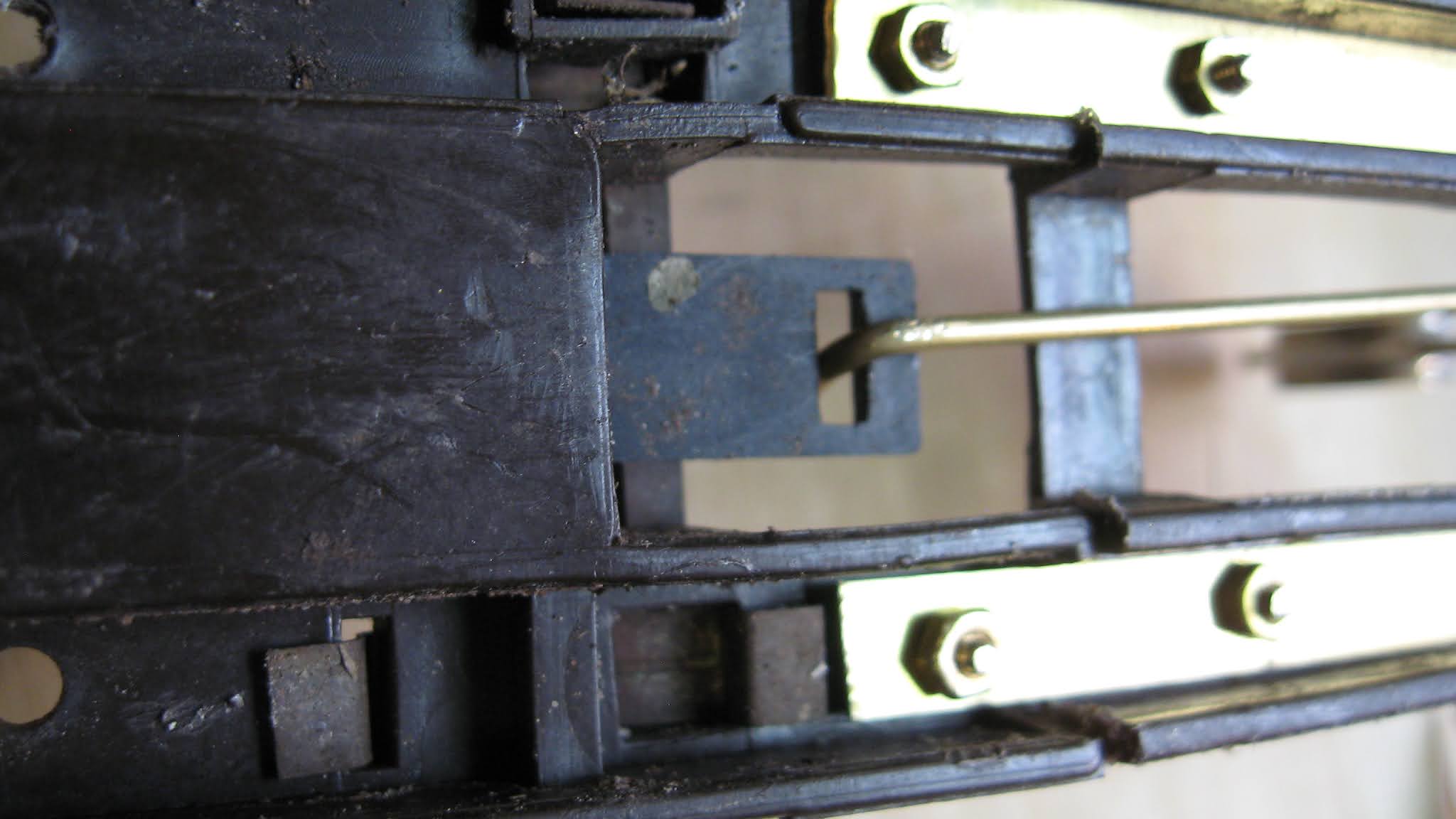
One end of a length of 2mm diameter brass rod was bent into a U-shape and passed through the hole in the end of the point lever
The lever and the tie-bar were put into their central positions and the other end of the brass rod cut off with around a 10mm excess. The end of the rod was then bent through 90 degrees and passed through the slot in the end of the tie-bar
The upper end of the rod was then bent again ......
..... and the lever tested.
I recognise that these levers are not entirely prototypical, but they are functional, they are relatively easy to construct and they do look more realistic than the LGB levers which I am replacing.
By shortening the distance between the pivot hole and the linkage hole
in the end of the lever it is possible to increase the amount of throw
on the lever - ie getting it to lie flat at the end of each throw.
However, I have found this prevents the point blades from being allowed to be trailed-though in the reverse direction, which is a feature I find useful. I might try experimenting with different distances between the pivot and linkage holes to see what effect this has on the operation of the points under different conditions.
Addendum
Since writing the above, I have made a few more point levers and have realised that the bolts look more realistic if they are inverted, so the nuts are on top rather than beneath the sleepers.
Washers are needed beneath the nuts at the turnout end, to stop them from sinking into the plastic.
Conclusion
As with most of my projects, these levers are a bit of a compromise between realism and practicability, but they work and, to my mind, are in keeping with narrow gauge railway practices. More importantly for me - a bodgeller - they are simple and fairly quick to make. Inevitably, one or two of them will get stepped-on when I have to cut the hedges behind the railway - but I am happy that it will not take too much effort for me to repair or completely replace any which suffer this fate.