The PLine Lister in its original form, was fairly basic in its construction and detailing.

Manual control was provided by a small bit of circuitry shrouded in heatshrink, connected to a potentiometer which was supposed to be operated by the brake wheel in the cab. However, the shaft of the brake wheel didn't engage with the shaft of the potentiometer and so it wasn't actually functional. I was discarding this piece of electronics anyway and so didn't bother to investigate further.

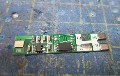
The existing wiring was removed and the space under the bonnet was measured. I discovered that two 103450 3.7v lipo battery packs would fit neatly inside. I removed the protection circuits from each pack and then wired them up in series .......

.... through a 2S battery protection board.

Unfortunately, the flimsy metal contacts on the battery packs kept snapping on one of the packs and so I was concerned that it would eventually fail. I decided to look for a more reliable source of energy.

I found that two 14650 1100mAh li-ion batteries would just about fit under the bonnet and so the 2S protection board was wired up to the batteries .......


The batteries and protection board were then wired up through a SPDT switch to a Deltang Rx65b receiver/ controller ........

..... and the aerial poked out through one of the vents to ensure that it would not be shielded inside the metal body of the loco.

The charging sockets were positioned beneath the front of the loco, .......

...... and the motor wired up to the output from the receiver.

Output pad A from was wired up to the cathode (neg) lead of the headlight LED and the anode (pos) leg of the LED was wired through a 270 ohm resistor to the positive supply. In addition to providing automatic forward directional lighting, Pad A enables the LED to mirror the LED on the receiver board whenever the receiver is not in receipt of a signal from the transmitter. Thus it can show when the receiver is in bind mode (rapid flashing) or when the battery voltage has dropped below a safe level (five flash).
 The circuitry was then powered-up and the receiver bound to one of my transmitters (I always use my Tx20 when testing and programming receivers).

The loco was then taken out into the garden and given some test running.

Despite the corrosion to the wheels, she ran very sweetly - in fact the rust would probably improve adhesion. I tested the range of reception between the transmitter and receiver and found that it was at least 20m (possibly more - that was the extent of the distance I could walk away from the loco in my garden).

This conversion was relatively straightforward, once I had identified suitably sized batteries for the space available. With the addition of some detailing, the loco would, I'm sure, become a useful addition to the loco fleet.


Manual control was provided by a small bit of circuitry shrouded in heatshrink, connected to a potentiometer which was supposed to be operated by the brake wheel in the cab. However, the shaft of the brake wheel didn't engage with the shaft of the potentiometer and so it wasn't actually functional. I was discarding this piece of electronics anyway and so didn't bother to investigate further.

The existing wiring was removed and the space under the bonnet was measured. I discovered that two 103450 3.7v lipo battery packs would fit neatly inside. I removed the protection circuits from each pack and then wired them up in series .......

.... through a 2S battery protection board.


Unfortunately, the flimsy metal contacts on the battery packs kept snapping on one of the packs and so I was concerned that it would eventually fail. I decided to look for a more reliable source of energy.

I found that two 14650 1100mAh li-ion batteries would just about fit under the bonnet and so the 2S protection board was wired up to the batteries .......


The batteries and protection board were then wired up through a SPDT switch to a Deltang Rx65b receiver/ controller ........

..... and the aerial poked out through one of the vents to ensure that it would not be shielded inside the metal body of the loco.


...... and the motor wired up to the output from the receiver.

Output pad A from was wired up to the cathode (neg) lead of the headlight LED and the anode (pos) leg of the LED was wired through a 270 ohm resistor to the positive supply. In addition to providing automatic forward directional lighting, Pad A enables the LED to mirror the LED on the receiver board whenever the receiver is not in receipt of a signal from the transmitter. Thus it can show when the receiver is in bind mode (rapid flashing) or when the battery voltage has dropped below a safe level (five flash).


The loco was then taken out into the garden and given some test running.

Despite the corrosion to the wheels, she ran very sweetly - in fact the rust would probably improve adhesion. I tested the range of reception between the transmitter and receiver and found that it was at least 20m (possibly more - that was the extent of the distance I could walk away from the loco in my garden).

This conversion was relatively straightforward, once I had identified suitably sized batteries for the space available. With the addition of some detailing, the loco would, I'm sure, become a useful addition to the loco fleet.


