Tuesday, June 15, 2021

Operating points remotely with servo testers

There are two sets of storage sidings on the Peckforton Light Railway - one is situated at one end of the line in the lean-to porch and the other is in the garage at the other end. Until now, the two turnouts at the throat of each set of storage roads have been controlled manually which usually entails hopping inside to change the points and out again when transferring stock to and from the sidings. This isn't a major inconvenience as the sidings are only used at the start and end of an operating session. However, I've always felt that it would be a lot easier if I could operate the points remotely from outside the garage and lean-to.

I solved the problem of operating the lean-to storage siding points by using point rodding (see Operate  points with simple rodding)

However, this option wasn't feasible for the points in the garage as the entrance is much tighter. I then wondered if I could operate them with servo motors - maybe controlling them with cheap servo testers.

These handy little gadgets can be bought for as little as £2.00(ukp) from a well known online auction site. They are used to test servos - twiddling the knob will make any connected servo move.

My mate Greg Hunter in Australia mentioned how Dave Bodnar had modified a tester to operate turnouts on his model railway and so I consulted Dave's article and started experimenting - http://www.trainelectronics.com/Servo-simple-controller/index.htm

I did a few initial experiments (see PostScript below) and found the modification I needed to make to the circuitry wasn't as complicated as Dave's original suggestion. He added a resistor, presumably because the amount of throw he needed for his 16.5mm gauge points was less than I needed for my 45mm gauge points.

So, here's what I did


The servo control box

Firstly, I bought a couple of servo testers from eBay, after checking with the seller that they did not go through an unnecessary initial warm-up routine when turned-on (see Postscript below)


The cover was taken off by pulling off the knob and ungluing the overlapping edge of the cover.

The board was flipped over and a wire was soldered to the middle contact of the potentiometer (the square thing with a knob on top in the middle of the board )

NOTE: Alternatively, the wire could be soldered to the middle leg on the upside of the board

The other end of the wire was then soldered to one of the contacts on a single pole double throw (SPDT) toggle switch

 NOTE: Any single pole on-off switch can be used - slide switch, latching push button, rotary switch.

Another wire was soldered to the middle contact on the toggle switch. Its other end was soldered to the negative pin on the board

 NOTE: The wire can be connected to any negative contact on the board or even on to the battery or power supply connector.

 At this stage I checked everything was working as anticipated and then adjusted the knob on the servo tester until the arm on the servo turned through the right amount of arc to operate the point when the toggle switch was flicked. On LGB points this is approximately 7mm.


Saturday, June 05, 2021

Progress Report 91

According to the meteorologists, May was one of the wettest since records began - and it felt like one of the coldest. However, the weather turned completely during the last weekend of the month and I was able to have a full running session which gave an opportunity to test out a few of the projects I had been working on during the bad weather.


Infrastructure

 Fencing

Owing to the poor weather, I was unable to do much out in the garden. However, following a tip-off from a fellow GardenRails forumite, I bought a few lengths of Fairy Garden fencing from eBay.

I hadn't seen it before, but I was told it's been around for a few years now but it seems good value for a 90cm length of fencing in the right scale. The palings are thin wood (similar to coffee stirrers) and they are held together with twisted plastic coated wire. This means the fencing is very flexible in both the horizontal and vertical planes.


Level crossing

 The first application of the fencing has been alongside the level crossing on the approach to Peckforton station.

To fix the fencing in place, I added some copper wire stripped from 13A twin and earth electrical cable. This was forced in behind the twisted wire of the fencing at roughly six inch (15cm) intervals and secured with a couple of bends, leaving a tail of around an inch (2.5cm) pointing downwards.

The tail ends of the copper wire brackets were then inserted into plastic rawlplugs forced into holes in the concrete breeze blocks which form the trackbed.


 Permanent way

Remote point operation

A couple of hard to reach points (turnouts) at Beeston Market and Beeston Castle stations have had push-pull point rodding added, using galvanised fencing wire and screw eyelets.


In addition, the two points for the storage sidings in the lean to can now be operated remotely from the entrance to the sidings with twist point rodding. 

For more information see Operating points remotely using simple point rodding


Stock

Double diesel

The double ended diesel loco which I 3D printed has now had its dummy trailer loco motorised.

It already had a 3D printed chassis which was designed to accept a motor and worm gear set from IP Engineering and so it was a quick and easy conversion. Four wheel drive was also added with Delrin chain and sprockets. 

 Although the locos are powered with cheap three volt can motors, the loco is now quite powerful coping easily with a train of eight loaded hopper wagons and a brake van up the 1:40 gradients on the railway.

In addition, the locos have been given name and number plates, drawn in TinkerCAD, 3D printed and painted. 

The names, Dorothy and Diana, as well as being alliterative with Double Diesel, are taken from two of the daughters of Lord Tollemache, the supposed benefactor of the Peckforton Light Railway.


Schull & Skibbereen loco

 The motorisation of the 3D printed Schull and Skibbereen loco (see How I drew and 3D printed a Schull & Skibbereen loco) is still being worked on. The original Bachmann Lyn motor block proved to be under-powered and so I have been seeking ways of improving its mechanical efficiency.  Initially, the difficulty was finding smaller diameter worm gears which were compatible with the original worm wheels. I tried using different gear sets but they weren't sufficiently robust. I then discovered that the worm gears on Bachmann motor blocks are fairly interchangeable and so I am presently redesigning the motor block to make use of the worm gears from another Bachmann loco.

Getting the gears to mesh reliably and smoothly is proving to be very difficult inside a fully enclosed motor block housing. 

However, I will not be defeated!


Second SR coach

 After developing the design of the Southwold six wheeled coach, I have now constructed a second one.

I discovered during a test run, that the centre truck kept derailing. Closer examination revealed that the arms of the swivelling mechanism on the outer trucks were 4mm too short. Not sure how this happened when I redesigned the trucks, but it just emphasises how critical the dimensions need to be.


A third coach should hopefully finalise the design.


 Cleminson open weathered

The six wheeled Southwold open wagon has now been weathered

I have now used the wagon twice on operating sessions and, touch wood, it seems to be performing well. It did derail on one of the points at Bickerton Station, but hopefully this will not be a regular occurrence.


Operation

Running session

Although the weather has generally been bad through May, it improved markedly towards the end of the month and so I managed to organise a full running session.


Using the Psion

During the running session, I made good use of my Psion pocket computer to manage the freight handling (see How I programmed my Psion 3a pocket computer for freight management).

I am very pleased with how my revisions to the original program performed. At the start of the session, the location of some stock didn't match where it was supposed to be according to the program. This is because through May, I had been having ad hoc running sessions and testing locos and new rolling stock and so the wagons had become displaced.

I found that the easiest way to change a piece of stock's location in the database was firstly to reset all wagons to Beeston Market and then use the List and Move functions to relocate stock which had found its way to other stations. 

<<< Previous Progress Report              Next Progress Report >>>


Wednesday, June 02, 2021

Operating turnouts with simple point rodding


 Several years ago I bought a large coil of galvanised fencing wire from my local agricultural supplier. I was intending to add it to the top of a wooden fence as an additional deterrent for animals. However, like most jobs of this type, I never got around to it.

Recently I was trying to find a simple way of operating some points (turnouts) remotely and remembered that coil of wire .... surely it could be put to good use ..... ???

Galvanised fencing wire is very stiff and resistant to bending - which makes it great for point rodding but tricky to manipulate. But, never willing to be defeated, I pressed on


Push-pull rodding

Ground level

A quick test rig was my first port of call - a length of wire and three screw eyelets to act as guides. I like to keep things simple.

Approximately 10mm at end of the wire was bent through 90° and flattened slightly by bashing it with a hammer so it would fit into the slot on the tiebar of the LGB R3 turnout. 


A loop was bent at the other end after measuring the how long the rodding needed to be.

NOTE: As the wire is very stiff, I used a vice and a hammer to make the bends.

Three screw eyelets were then opened up slightly, by firstly screwing each one into my workbench ...

... and giving the eye a twist with a pair of pointed-nosed pliers.

The eyes need only to be opened sufficiently for the wire to slip in.


The eyelets were then screwed into the baseboard (if it had been concrete, I'd have drilled holes and inserted rawlplugs) and the wire threaded into them, before being squeezed closed again with the pliers.


The system clearly worked. As the wire is very stiff, the eyelets or 'stools' need only to be at around nine to twelve inch intervals (22 - 30cm).


Below baseboard level

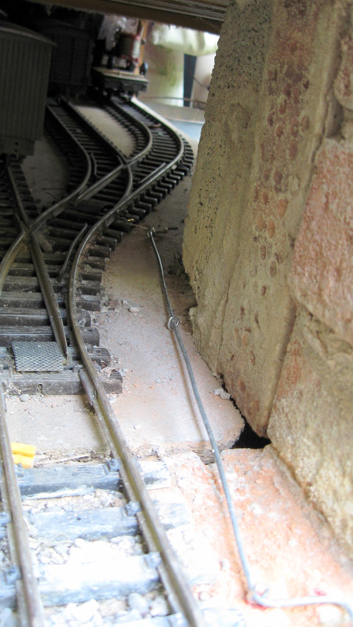
The experiment was successful but I decided to install the rodding below baseboard level as the points which needed to be controlled were on the far side of the baseboard at Beeston Market and the rodding would have to cross the platform and several intervening tracks. 

The same system was employed with a couple of slight modifications. 

Sorry about the poor photo, but it was dark under there!

 Firstly, the bend at the turnout end of the rodding was extended to around 1½" (36mm) to allow it to reach the tiebar from below baseboard level.

Secondly, while drilling the slot for the lever, I snagged the slot on the tiebar, totally destroying it, and so I wrapped a loop of brass wire around the top of the lever and extended it beneath the tie bar to engage the slot on the opposite side.

The operating handle at the other end of the rodding was exactly as in the prototype


Below baseboard level - v2

At Beeston Castle, the tracks are mounted on concrete (breeze) blocks and when I recently relaid the tracks there, I took the opportunity to install some plastic tube in a shallow 'trench' beneath the platform and adjacent track.

The galvanised wire was a bit of a tight fit in the tube and so I used a length of 00 gauge nickel silver rail instead

The operating end of the rail was bent upwards to slot into the tiebar.


Twist point rodding

It's not always convenient for point rodding to be installed for push-pull operation without the need to a series of bell cranks to turn the motion through 90°. Whilst this would have been possible, I decided it was too fiddly to be fixed in place at the next location - the two points leading into the storage sidings in the lean to at Bickerton Station.

I then hit upon the idea of twisting the rodding rather than pushing and pulling it to transfer motion from the lever to the tie bar..


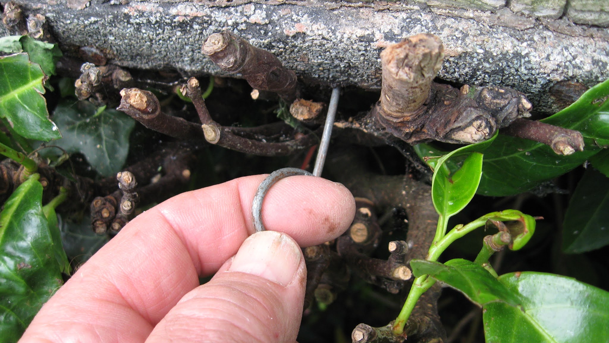
To give the required movement at the turnout end of the rodding, three bends needed to be made.

I found these quite tricky to form, as the wire is very stiff. After a couple of abortive attempts I discovered the easiest way to do it was to mark the wire at three half inch (12mm) intervals  .....

.... form the innermost bend first in the vice, .....


.... followed by the middle bend and then the outermost bend. 


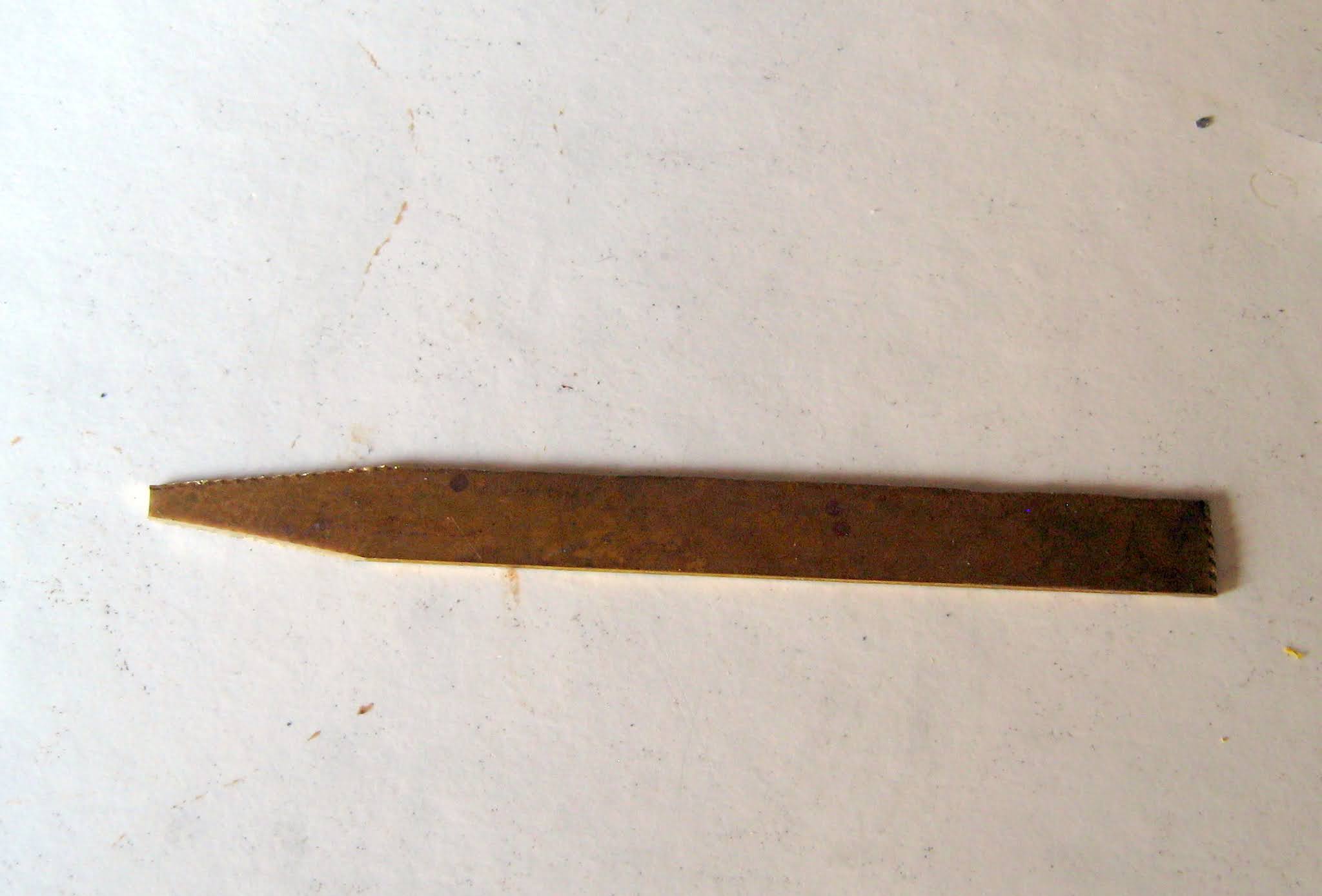
A piece 9mm wide by 0.6mm thick brass strip (approximately 25mm long) was then trimmed to a blunt point at one end .....


..... before being wrapped around the wire on the middle bend.

This will connect the rodding to the slot in the tie bar by forming the pointed end into a hook


The other end of the rodding was bent into an operating lever and the eyelets were installed as previously.

As an be seen, the outermost eyelet was screwed into a rawlplug inserted into a hole in the brickwork of the lean to.

The rodding for the second point required a little more effort as it was more distant and fairly inaccessible without dismantling most of the shelving above the storage sidings. However, with a bit of grunting and a few curses, I hacked a chunk off the internal blockwork to allow it to cut the corner and then installed the system as previously


You may notice that I've ensured that the actuating levers lie flat. This is deliberate as, in the confined space, I don't want then to foul the stock as it emerges from the storage sidings.


Conclusion

I don't recall seeing this system described previously, but as it's very low tech way of solving the problem of operating turnouts remotely I'm sure I'm not the only person to have thought of it.

I would imagine that the twist system could be made to operate with gentle curves in the wire. I suppose it might also be possible to combine the two systems to turn a twist into a push-pull to turn the movement through 90°.  The main limitation would be finding a way of bending the wire to make loops to connect one system to the other though I'm sure that other who are more dextrous and ingenious than me will not find it a problem.

My present system uses chrome plated steel eyelets. It would probably be better to use stainless steel eyelets though, at present, the only ones I can find are too large. I'm hoping I might be able to track down some smaller versions for my next application of the system - a lever frame at Bulkeley Station.