The signals
I constructed nineteen lower quadrant signals to control train movements in and out of the five stations on my railway. The signals were scratchbuilt using a variety of materials - wood, brass, copper and plastic (See How I constructed some semaphore signals).
Once I had constructed them, the next issue was how to control them. I considered mechanical control, using a ground frame and cables but, because of their fragility, I wanted something which would easily enable me to remove the signals when the railway was not in use. An electro-mechanical system seemed to me to be the most appropriate approach. The next question was - 'How?'
The electronics
My first priority was cost. As I had nineteen signals, I wanted a system which was not going to break the bank (particularly as I am now living off a pension). I hunted around (mostly eBay) for a cost effective radio control system which might meet my needs and came across these keyfob r/c systems which can control up to four outputs. As my stations each required no more than four signals, this seemed like the ideal solution - and what is more they cost under £5.00 for the complete system of receiver and transmitter. Five sets were ordered from China.
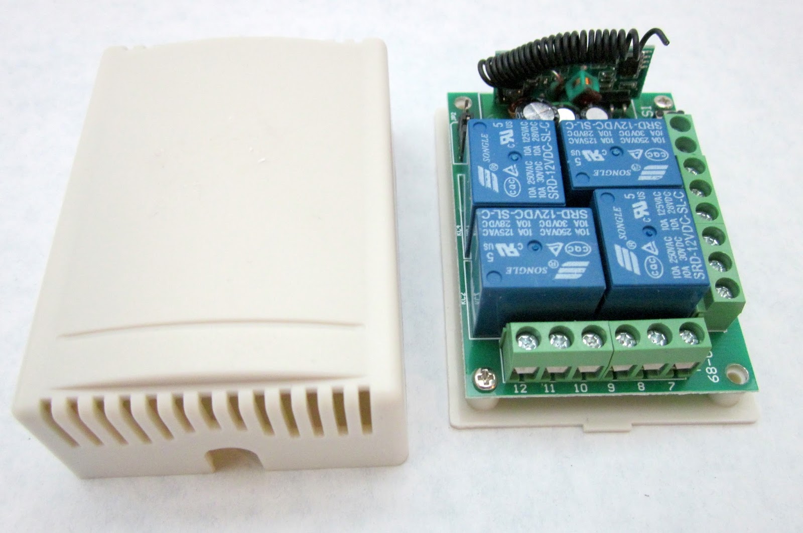

Having sorted out the radio control aspect, the next problem was to figure out how to turn the output from the receiver into something that could operate servos. Fortunately, my modelling mate in Australia is very familiar with using Picaxe processors to interpret radio control signals and turn them into something useful for garden railway. Greg Hunter has a highly informative and accessible website on which he shares his expertise - http://www.trainweb.org/SaTR/Picaxe%20tutes.htm . A few email conversations later and I had the necessary information for interfacing the output from the r/c receiver with a Picaxe 14 Project board.


The program
Greg proved very helpful in devising the bounce procedure for the program and advising on the coding for triggering the actions. The program for the Picaxe board interprets the signals from the remote control receiver to determine which button had been pressed on the handset. It also remembers the position of each of the four signals and so subsequent presses of the button on the transmitter will change the signal from on to off and vice versa.Outline of the procedures in the program
Init procedureThis ensures that all the signals are put into the 'on' position (ie set to danger) when the program is initiated
Starter
This checks the state of the outputs from the receiver and compares that with the stored position of each signal arm. If it receives a signal from the receiver, it then goes to the relevant sub procedure to raise or lower the signal arm.
Raiseit
As implied, this procedure raises the signal arm, calling the first and second bounce procedures to simulate the effect of the bouncing signal arm
Lowerit
As above, but lowers the signal arm
(Note: Explanatory comments in blue)
'FOUR semaphore signal driven by servos with bounce
'bounce2semaphore v1.bas tested 10/6/14 364 bytes
'assumes a constant acceleration going to STOP,
'constant speed going to clear (down)
'controls 4 signals. Same bounce routine used for each
'raising bounce equations are:
'for initial rise: R=160t*t-50 degs for t<0.56s
'1st bounce down and up: R=87(t-1.04)^2-20 degs for 0.56<t<1.52s
'2nd bounce down and up: R=68(t-1.84)^2-7 degs for 1.52<t<2.16
'this is for Clockwise rotation direction to raise arm to STOP
'constants for raising
symbol lowered=170 '10us counts NB coincidence of equation coeff of t squared!
symbol raised=110 'counts
symbol initcoeff=160 'coeff of t squared in equation for counts =50/0.56^2
symbol bounce1coeff=87
symbol mincounts1=132 'min counts of first bounce (raised+20)
symbol bounce2coeff=68
symbol mincounts2=118 'min counts of 2nd bounce (raised+7)
'constants for lowering:
symbol bouncelow= 176 'counts for 72deg
symbol bouncelowup=158 'counts for 40deg
'variables:
symbol sig1state=b0 '0=clear(down), 1=stop(up)
symbol sig2state=b1
symbol sig3state=b9
symbol sig4state=b10
symbol t=w1 'time in ms
symbol t1=w2 'intermediate value in eqns
symbol S=b6 'location of servo in 10us counts
symbol k=b7 'loop counter
symbol sigpin=b8 'the pin number for that signal(1 to 4)
'--------------------------------------
init:
pulsout B.1, raised
sig1state=1
pause 20
pulsout B.2, raised
sig2state=1
pause 20
pulsout B.3, raised
sig3state=1
pause 20
pulsout B.4, raised
sig4state=1
pause 20
starter:
'check inputs and refresh servo pulses
'signal 1
sigpin=1
if pinC.1=1 and sig1state=0 then 'need to go to stop/raised arm
S=raised 'initial setting for raiseit subroutine
gosub raiseit
sig1state=1
pause 20
elseif pinC.1=1 and sig1state=1 then 'need to lower it to clear
S=lowered
gosub lowerit
sig1state=0
pause 20
endif
'signal 2
sigpin=2
if pinC.2=1 and sig2state=0 then
S=raised
gosub raiseit
sig2state=1
pause 20
elseif pinC.2=1 and sig2state=1 then
S=lowered
gosub lowerit
sig2state=0
pause 20
endif
'signal 3
sigpin=3
if pinC.3=1 and sig3state=0 then
S=raised
gosub raiseit
sig3state=1
pause 20
elseif pinC.3=1 and sig3state=1 then
S=lowered
gosub lowerit
sig3state=0
pause 20
endif
'signal 4
sigpin=4
if pinC.4=1 and sig4state=0 then
S=raised
gosub raiseit
sig4state=1
pause 20
endif
if pinC.4=1 and sig4state=1 then
S=lowered
gosub lowerit
sig4state=0
pause 20
endif
goto starter
raiseit:
'for initial rise: R=initcoefft*t-initdegs in degs with t in sec
'so R=initcoeff/1000000 *t*t-initdegs degs for t in ms
'to convert to counts,
' R=initcoef/1000000*t*t-lowered
if S<raised then firstbounce
t=t+25 'add 25 ms but pause later is less than this to make it go faster
S=t/10*initcoeff/100*t/1000
S=lowered-S
pulsout sigpin,S
pause 17
goto raiseit
firstbounce:
'S=-bounce1coeff x (t-1.04)^2 + mincounts1
S=raised
FB2:
if S<raised then secondbounce
t=t+25
if t<1050 then
t1=1050-t
else
t1=t-1050
endif
t1=t1/5*t1/100 'square it
t1=t1*bounce1coeff/2000 'intermediate num
S=mincounts1-t1
pulsout sigpin,S
pause 16
goto FB2 'firstbounce
secondbounce:
'S=-bounce2coeff x (t-1.84)^2 + mincounts2
if t>2140 then finished
t=t+25
if t<1850 then
t1=1850-t
else
t1=t-1850
endif
t1=t1/4*t1/50 'square it
t1=t1*bounce2coeff/5000
S=mincounts2-t1
pulsout sigpin,S
pause 15
goto secondbounce
finished:
t=0
pause 20
return
'+++++++++++++++++++++++++++++++++++++++++++++++++++++++++++++++++
'lowering linearly
'takes 580ms to go from horiz to -55 deg, bounces up to -40 deg in 380ms
'then drops to -50 deg in 380ms, and stops there. total 1340ms
'these just a copy of actual declarations at top, for ease of reference....
'symbol bouncelow=176 'counts for 55deg
'symbol bouncelowup=158 'counts for 40deg
'symbol lowered=170 'counts for 50deg
'symbpl raised=110 'counts for horizontal 0 deg
lowerit:
for k=raised to bouncelow step 3 '66/3 counts in 580ms gives 26 ms/count
pulsout sigpin,k
pause 20
next k
'pause 100 (Might be needed)
for k=bouncelow to bouncelowup step-1 '18 counts in 380ms gives 21 ms/count
pulsout sigpin,k
pause 18
next k
'pause 100
for k= bouncelowup to lowered '12 counts in 380ms gives 31ms/count
pulsout sigpin,k
pause 27
next k
pause 20
return
Installation
Small servos were mounted at the base of each signal, with a bell crank linking the servo arm to the signal operating wire.

The receiver board, the Picaxe board, the voltage regulator board, an auto reset fuse (1.6A) and an on/off switch were mounted in an airtight container.

Power was provided by a 12v lead-acid battery designed for use with burglar alarm systems.

The battery and the encased electronics were housed on a purpose-built ledge beneath the baseboard ......

.... and the control leads and the power supply cables for each of the signals were connected through two three-way plugs and sockets to the distribution cables for each signal.

Suitable resistors for the 4.5v supply to the signals were soldered to the LEDs in the signal lamps .....

..... and holes were drilled into the baseboard at Beeston Market station to accommodate the servos beneath each signal.

The signals were then connected to the underboard wiring with servo plugs.

...... and I was pleased to find the signal LEDs actually worked.


The whole system was then given a thorough testing .......
Conclusion
One of the delights I have in garden railway modelling is the opportunity it affords for pushing the boundaries and learning something new. With my interest in IT and ICT, I had dabbled with control programming in an educational setting for quite a few years but this project enabled me to explore a new area - programming PIC chips and applying this knowledge to the solution of a real problem. There is no better way to learn something new than to develop new knowledge and skills for a purpose. Book learning has its place, but for real learning - there is nothing like the application of knowledge to experience!I still have to solve the problem of how to deploy the signals at the four other stations around the railway. These are all at ground level and so it will be difficult to put the servos beneath each signal. The will probably be sited at the base of each signal above ground level. Although this may make the signals appear slightly less realistic, I think it's a small price to pay for having them operational.
Although very few narrow gauge railways in the UK used signalling (eg the Southwold, the Isle of Man and the Ffestiniog), I feel that seeing white signal posts and red signal arms in the garden setting adds a certain something to the attractiveness of the a garden railway. Even better if the signals are illuminated and animated!