Saturday, June 24, 2023

Progress Report 97

This is an interesting time of year for Peckforton Light Railway. As the days grew longer, things started gearing up in preparation for the first full running session of the season. However, this was very much dependent on the weather. To set up the first full running session I really need to have a guarantee of three consecutive rain free days: half a day to clear the track and set up the buildings and other lineside accoutrements, half a day to deploy and check the rolling stock, half a day to prepare the running schedule and then a day and a half to run a full operating session. In actuality, I sometimes need four full days as a fair bit of time is taken up with caring for my 102 year old mother in the meantime, so I can't rely on having interrupted days for running trains.

However, running stock has been constructed, running sessions have been completed, visitors have been catered for, videos uploaded and some outdoor jobs completed.


Rolling stock

Hunslet - Hughie

Ever since I started with my garden railway, I have been intrigued by the 16mm scale card models produced by LocoLines - now produced by Rail-Road. After seeing an article in Garden Rail detailing how a modeller makes all his 16mm stock from card, I decided to give one of the Rail-Road card kits a try. In my previous Progress Report, I outlined construction of the basic kit - but since then I have enhanced the kit with a decent motor block, a new chimney, backhead detail, new springs and sandboxes and handrails and pipework.

The additional 3D printed detailing parts are available as free downloads on the Thingiverse.com website (registration required) and the GardenRails.org forum (registration required)

For more information see How I assembled a Rail-Road card kit

I am now in the process of producing a 3D printed version of a similar loco and am trying to decide whether to replace the card version or complement it.


GVT Glyn motor block

In my previous progress report I described how I had constructed a 3D printed model of a Glyn Valley Tramway Beyer Peacock tram loco. I was disappointed with the performance of the Bachmann motor block I had used to power it .....

..... and so designed and 3D printed a replacement using an MFA Como gearbox motor.


However, I was also disappointed with this motor block's performance and so have now designed and 3D printed a second replacement using a larger and more powerful gearbox motor.


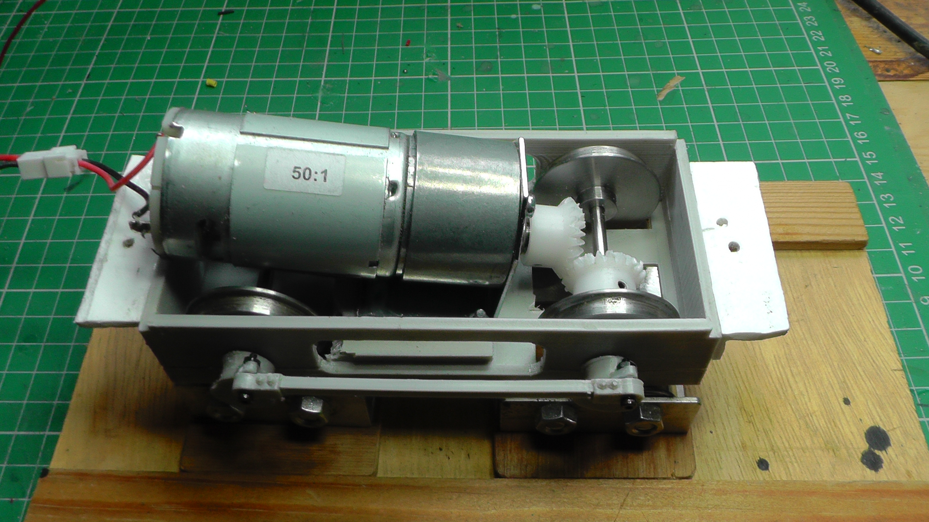
This has much better performance.


For more information, see How I created my own motor blocks (pending)


Directors' Saloon

This has been on my To-do list for many years but, having now completed the gatehouse for Peckforton Castle (see below), I felt it was time to make this plan a reality. The saloon is based on one of the various designs of Glyn Valley Tramway four-wheeled coaches (see How I constructed a GVT coach).


For more information see How I designed, printed and constructed a Directors' Saloon


Permanent Way and Infrastructure

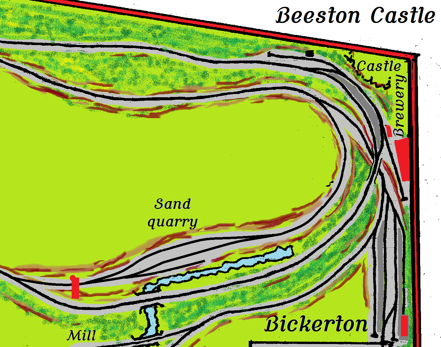
Sand Quarry Extension

The siding for the sand quarry installed in 2018 (see Progress Report 75), was always slightly short - primarily because the space for it was quite tight.

I toyed with a few ideas for extending it, but eventually opted to turn the siding through 90 degrees and turn it into a link back to the mainline just outside Peckforton station. This provided an opportunity for me to designate this new junction as a siding to serve Peckforton Castle (bottom left on this plan).

The extension has now been constructed and its track tested and ballasted.


For more information see How I built the sand quarry extension


Lineside

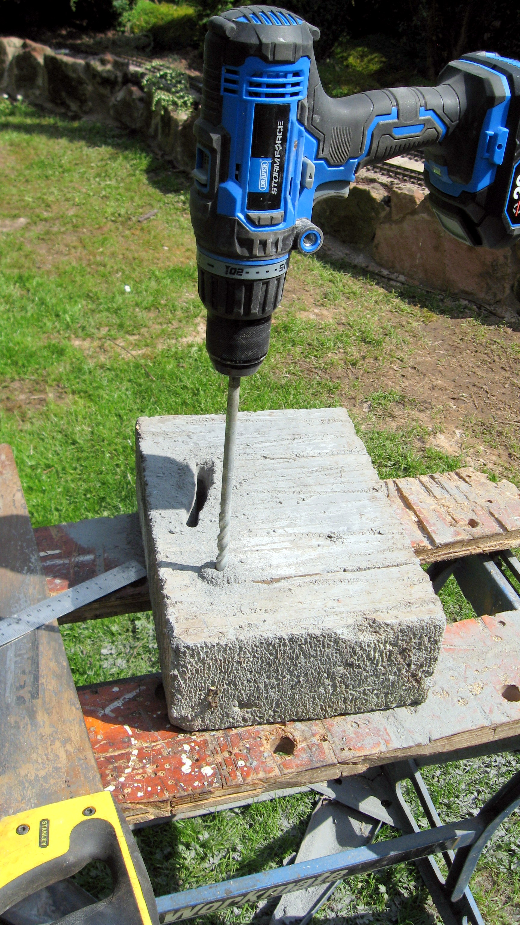
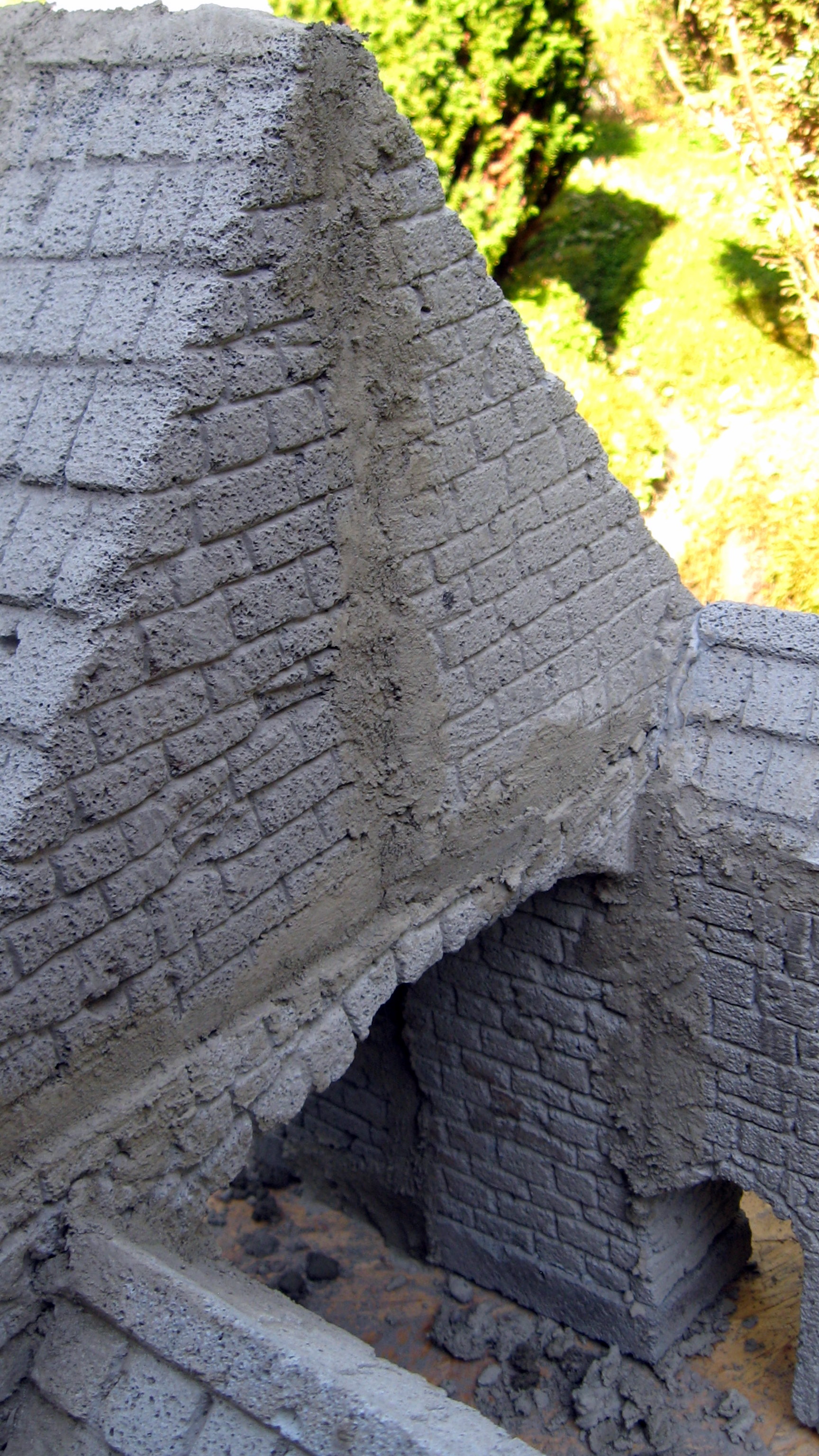
Peckforton Castle Gatehouse

With the completion of the sand quarry extension and its incorporated junction for Peckforton Castle, I decided the entrance to this new siding needed to be recognised with a new structure. The resultant gatehouse was based on the gatehouse for real vehicular entrance to the castle.

My model was carved from four Thermalite blocks.


Operation

Operating sessions

As indicated above, my first operating session of the year has been delayed slightly by a range of conflicting factors. However, one full session has been run plus a couple of smaller scale partial operating sessions


Visitors

In addition, the railway has hosted a visitation by Zach Bond and his mate Theo who spent an afternoon (and evening) running live steam and a range of other scheduled and unscheduled train services.


Freight management Mk V

Over the years, I have produced four versions of my computerised freight management system:

They have each had their strengths and weaknesses. My favoured version (Mk III) was that which ran on my Psion 3a pocket computer but it's limitation was the 1Mb of RAM provided by the Psion - it would sometimes run out of memory half way through a running session.

So, I acquired a Psion Series 5 with a staggering (for 1997) 8Mb of RAM. However, because it's difficult to interlink Psions with modern computers, I had to hand type the code, copying it line by line from my old 3a to the Series 5. Some amendments needed to be made to the coding to take account of differences in the two machines' LCD displays and also some variations in the way the coding is handled but, after some cerebral effort and hard graft I now have a working version of the software on the Series 5


More figure scanning

Following Dean's (from DesignScanPrint3d) previous visit to 3D scan members of our local dramatic society in 1930s and 1940s costume - see Progress Report 95  


he paid us another visit to scan more figures, this time with more specific poses. I have now received the first batch of figures from him.


As you can see, these figures are more engaged in activities, rather than static poses. There will also be some seated figures to become passengers in my rake of recently finished GVT coaches (see Progress Report 95)


Other developments

Year long video

I am steadily working my way through my schedule to record the next monthly instalment of the Year Long Journey videos - depicting a mixed train travelling Down and back up the line in twelve monthly stages. 

June's Down sequence sees the train arriving at Peckforton and having some wagons shunted off and on by Doris, the timber yard's shunter.

While the Up shot is of the train passing the water mill on the approach to Peckforton.


By September the train will have completed its two journeys and I will be able to compile the two videos.


3D printer repairs

3D printers require a certain amount of nurturing to keep functioning successfully. My budget (£70) Anet A8 printer developed a fault which required the replacement of the heated bed.

Sometimes, it takes longer to track down the source of the fault than it does to repair it.

So, all in all, it has been quite a productive period since my last progress report. Despite not having had time to engage in more than one operating session, there have been plenty of other jobs to keep me actively involved. As the summer progresses, I aim to run quite a few more trains.


<< Previous Progress Report         -      Next Progress Report >>

Monday, June 12, 2023

How I constructed a gatehouse for Peckforton Castle


When I constructed the new extension for the sand quarry (see How I constructed the sand quarry extension), I decided that the furthermost end of the extension would link back on to the main line as it approached Peckforton Station.


I decided that this new junction (bottom left on the above plan) would act as a siding for Peckforton Castle. In my imagined history of the railway, Lord Bentley Tollemache, the owner of Peckforton Castle when the Peckforton Light Railway was constructed, was a great supporter of the new railway and so it seemed inevitable to me that he would have persuaded the company to construct a siding to serve his estate. To signify that the by line from the new junction was entering the castle grounds, I decided to erect a gatehouse over the entrance to the siding (shown in red on the above plan). It seemed sensible to model this gatehouse on the one which actually exists spanning the roadway leading to the castle.

Source: https://www.geograph.org.uk/photo/2882447

Having previously constructed the ruins of Beeston Castle by carving Thermalite blocks (see How I created Beeston Castle), I decided I would use similar techniques to create the gatehouse. The major difference was that this time I didn't want it to look like a ruin and so I felt I needed to be a little more careful.

The first job was to work out how many blocks I would need by test fitting a block to the intended site of the gatehouse.

I had fortunately been given a couple of cylindrical plugs of Thermalite by my neighbour who, four years ago, had an extension built on to his house. At the time, I had no need for them but they were squirreled away until a need arose.

The largest item of rolling stock was used as a template and the block was scraped with a screwdriver to indicate the location of the archway.

The block was cut to size using an old panel saw.


The sides of the archway were also sawn and then a series of holes were drilled along the line of the upper edge of the archway using a masonry bit (I could have used an drill bit intended to for metal drilling but it would not have been useable for metal drilling afterwards).


Once a series of holes had been drilled, they were interlinked by drilling at an angle, ......

.... until the segment of the block forming the archway could be removed.

The inner surfaces of the archway were then smoothed off with a wood rasp.

The apex for the upper section of the gatehouse was marked out and sawn from another block of Thermalite.

The spire for the turret was then filed from an offcut of Thermalite

The main structure of the gatehouse was then test-fitted.


At this point, I realised the structure looked a bit flimsy for such a supposedly important edifice and so I visited my local builders' merchant to purchase another couple of blocks. There were then shaped as shown above to increase the depth of the archway and to add a couple of extra wings to the rear of the gatehouse.


The next stage was to smooth off the outer surfaces of all the blocks with a rasp. I probably could have used a powertool to speed up and ease this process but the thought of the dust cloud this would create deterred me and so each block was smoothed off by hand.

Now came the fun part, marking off where doors and windows would be situated and beginning the process of carving mortar courses for the stonework.

Arched mullion window frames and arched doors with frames were drawn in 3D using Tinkercad ....


.... and printed out.


The files are available as downloads on Thingiverse, by the way. The position of the windows and doors was then decided upon and these were roughly scratched on to the blocks using the frames as templates. The windows were tackled first.


The outline for the arched stonework over the windows was then scribed on and another outline of the window approximately 5mm inside the original.


The inner outline was then hollowed-out with a flat bladed screwdriver to a depth or around 15mm,

The gap between the inner and outer outlines was then recessed to a depth of around 5mm.

This is to allow the window frames to be recessed into the stonework. Some slight adjustments were made to the openings to make sure the window frames sat neatly (and horizontally) in their recesses.

The courses between the arched stonework were then scribed on ......


.... and the frames test fitted to check the effect/

The horizontal mortar courses were measured (1.5cm) and scratched on to each face with a flat bladed screwdriver.

Recesses for the doorways were similarly chiselled out, though only the shallow 5mm rebate was needed rather the additional 15mm chiselled recess.


The vertical courses were then indented using the screwdriver blade. It's easier to control where the blade goes by pressing rather than scribing as the blade tends to wander, especially if it hits a denser patch.

The mortar courses were completed for the whole building. A somewhat tedious and messy business but I tried to save as much of the resultant brick dust as I could so I could subsequently mix it with cement to make a filler.

The roofs were tackled next. The horizontal courses were marked out (4cm wide) and were then filed into rachet style steps with a rasp. 


The vertical divisions between the tiles were then impressed with the screwdriver blade.


With all the various sections of the building now suitably scribed, it was now time to join them together. 


Grey CT1 filler adhesive was squidged on to all the relevant parts which needed to be joined .....

......  and then string was tied around the parts. Lollypop sticks were wound into the loops of string to tighten them,

The structure was then left for 24 hours to allow the adhesive to set.


The various cracks, dints, nooks and crannies now needed to be filled. I mixed a paste of cement and sifted block dust from the sawing, gouging and scribing in a 1:1 ratio. I wanted it to last! This was then forced into the crevices with a small trowel and wooden coffee stirrers.


This was allowed to set for another 24 hours and then the mortar courses were then rescribed where they had become filled.

Various colours of cement dye were now painted on - red, brown and buff for the sandstone walls and black for the roof tiles.


The dyes were painted on diagonally with a stiff brush to avoid filling the mortar courses. However, it was easy enough to rescribe any courses which accidentally got dyed. The recesses behind the windows were dyed black.

After the black dye on the roof had dried, ......

....... the slates were lightly sanded with a sanding block to restore the grey of the Thermalite blocks but to leave the black in the joins between the slates.

 The window frames ......

..... and door frames were primed with grey primer and then painted with Rustoleum textured paint. The doors were masked before being sprayed,


Once the paint had dried, the masking tape was removed from the doors and they were painted brown, with the studs, hinges and handles painted black using acrylic paints.


The windows were glued to a sheet of clear plastic (retrieved from some packaging) using clear Bostik adhesive.

Once the Bostik had set, a sharp knife was used to remove each window from the sheet.


The windows and doors were then glued into place using Pinkgrip adesive.

The adhesive was squidged into the recesses ......


.... and then the window or doors pushed in. Excess adhesive was removed with vinyl-glove clad fingers and / or transferred to any gaps. The dyes tended to mix with the adhesive enabling it to blend in with the adjacent stonework.

Once the adhesive had set, a few places were touched-up with dyes and then the whole thing was given a couple of coats of semi-matt varnish to seal everything.

It's not a perfect model, by any stretch of the imagination, but it will be durable and weatherproof. My model of the ruins of Beeston Castle have been outside for for nearly five years now and, although the colours have faded slightly, the structure is as sound as it was when it was created.

I have learned a lot from creating this model. I'll certainly be prepared to construct another, using the lessons learned from this one - make the roofs slightly wider than the building so they overlap - align the sections more carefully when gluing them together.

However, I am quite pleased with the outcome. Now the trackwork on the Sand Quarry / Peckforton Castle extension has proved to be reliable, I will ballast the track and at the same time embed the building into the surrounding ground.

I think the building is in keeping with the original and certainly provided a focal point for this stretch of track.


It has already featured in the video of my most recent running session and seems to already have become integrated into the landscape.