Over the winter, understandably, most of the jobs I undertook on the railway were indoor ones but I have also managed a few outdoor jobs as and when weather permitted. Developments since the last Progress Report include:


Work is progressing on the interior, constructed from various sized sections of strip wood and all manner of 'reclaimed' materials.

I am in the process of bashing a plastic model of a beam engine into something vaguely resembling a mill engine which will eventually be connected to the machinery via a series of pulleys 3D printed for me by a fellow modeller.



Reprogramming an Rx102 to provide triggers for sound cards
Adjusting servo throws from an Rx102

- finishing off the water mill and sluice gate,
- landscaping the area around the mill, including the provision of a mill stream,
- starting construction of the sawmill for Peckforton Station,
- ballasting the re-aligned track near Bulkeley,
- constructing two new small diesel locos from kits,
- experimenting with replacements for LGB couplings
- reprogramming the receiver in Loco No.1 to provide auto station stop,
- and making some videos for fellow modellers on how to reprogram and adjust the outputs from various Deltang receivers.
Lineside
Water Mill
The water mill is now more or less completed (see How I constructed the water mill). The sluice gate has been installed (see How I constructed a sluice gate) and the area landscaped to include a mill stream and the planting of a dwarf rhododendron which will eventually grow into a small tree.

Sawmill
The main structure for the sawmill is now finished using a range of materials; wood, aluminium foil, brass channel and copper tubing (see How I constructed the sawmill).


Permanent Way
Ballasting
After eliminating a hump in the track on the approach to Bulkeley station, adjacent to the junction for the copper mine branch (see Progress Report 71), it was some time before I got around to ballasting it. I used my now preferred method, three parts horticultural grit to one part cement - brushed into place while dry and then soaked with a watering-can rose.

Rolling stock
I realised that all the accounts of battery and radio control installations on my blog were quite complex as they also included wiring up lights and/or soundcards. I therefore decided to construct a couple of basic diesel loco kits and keep the radio control installations as simple as possible.
HGLW diesel loco
I opted for HGLW's most basic loco body (LB1) and their Deluxe 4wd chassis - for a total of around £40.00. The kit was very easy to construct and the battery and radio control installation very straightforward (see How I constructed a HGLW diesel loco kit).

IP Engineering Albert
The IP Engineering basic diesel loco kit was slightly more expensive at £45.00, though I needed to spend another £8.00 for Delrin chain and sprockets to provide 4 wheel drive. Without it, the loco has quite limited hauling power. The kit was quite straightforward to construct and battery and radio control installation relatively easy. (see How I constructed an IP Engineering Albert loco)

Couplings
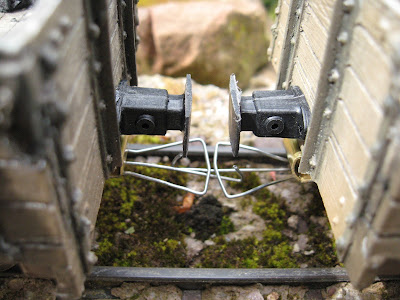
I have retained LGB style couplings on all my stock because I really enjoy shunting and so I need couplings which are easy to couple and uncouple, are reliable and, most importantly, are cheap. However, LGB couplings are unrealistic and obtrusive. For a long time I have been exploring alternatives but failed to find anything which met all my criteria.
However I have just reached the conclusion that, rather than looking for alternatives, why not use the LGB coupling principle but find a way of making them less obtrusive. After a bit of experimentation, I have made some couplings from a piece of brass and some wire which seem to fit the bill.


At present, these are just prototypes, but they do seem to work OK and so I am planning to install them on several items of stock so I can give them a thorough testing. The advantage is that they are compatible with LGB style couplings and so I should be able to convert the stock in batches rather than having to refit all 75 items of stock at the same time.

Control
Peckett Loco No.1 has been a stalwart of the line since the early days of its Anglicisation (see How I constructed a Peckett loco from a GRS kit). I thought it would be interesting to re-program a couple of locos to stop automatically at each station as they trundled around on days when I had visitors or when I was gardening. Loco No. 1 has now been reprogrammed (see How I reprogrammed a loco for auto station stop).Various Deltang video guides
Programming an Rx102 for latching on/off outputsReprogramming an Rx102 to provide triggers for sound cards
Adjusting servo throws from an Rx102


