Sunday, November 07, 2010

Fitting a decoder to a GRS kit on an LGB ToyTrain 0-4-0 chassis

Introduction
The ubiquitous LGB/Playmobil 0-4-0 Toytrain chassis were (and to a large extent still are) the mainstay for many 45mm gauge kits and conversions. They formed the basis for the locos in basic starter sets - such as Otto:


OHO

and Rusty.

 They are also used for the Playmobil diesel shunter.

These chassis are quite basic in design but fairly robust and have the advantage that they do not have rubber traction tyres which are the bane of the Stainz and other 0-4-0 chassis. I have so far used two of these chassis as the basis for my kit-based conversions - see How I made a Peckett from a GRS kit and How I made a Hunslet from a GRS kit. I also intend to convert the Playmobil diesel into something more UK-based - such as this 1935 Fowler:

 ...... but that's another story (see How I converted a ToyTrain diesel into a Fowler(ish) loco).

Fitting the decoder
The first stage of of chipping the chassis was to strip down the donor loco to remove the body from the chassis. This was a fairly straightforward process, requiring the removal of half a dozen screws.

The next stage was to remove the cover holding the motor in place by removing two screws:

The cover lifts straight off to reveal the double ended motor.

This simply lifts out. When fitting a decoder, it's important to isolate the motor connections from the pick-ups. This could be achieved by bending back the motor contact tags so they are no longer touching the vertical wire pegs which supply the current from the wheels and pick-ups. However, given the cost of decoders for G scale, I prefer something a little more reliable. I turn the motor around so the motor contacts have no chance of accidentally touching the leads from the pick-ups. To accommodate the motor contacts, a slot needed to be cut in the opposing chassis member. Two cuts were made on either side of the hole in the cross-member with a razor saw.

The plastic was removed by 'persuasion' from a pair of pointed-nose pliers. The hole in the chassis-member meant the plastic could be bent outwards until it snapped off. A needle file was used to do the final tidying up.

The motor was fitted back in temporarily to check clearances (Note the two pick-up wires now at the other end of the motor).

A similar slot needed to be cut into the flange on the motor cover, to provide sufficient clearance for the tag on the motor. Again, a razor saw was used.

Two holes were drilled in the other flange of the motor cover to take the leads from the motor contact tags to the decoder:

The decoder (a Massoth L or an LGB 55020 or 55021) was tucked into the boiler on each of my two conversions. The sockets were snipped off the ends of the motor leads (yellow and green)........

..... and the leads were then soldered to the motor tags after being threaded through the holes in the flange.

The motor cover was then screwed back into place, making sure the leads did not foul the motor mechanism, and the leads for the track pick-ups were pushed on to the pick-up connectors which protrude from the top of the motor cover.

The bodies of the locos were then carefully fixed back on to the chassis, making sure none of the leads were trapped in the process. The locos were then placed on the track, programmed and tested.

Sunday, October 31, 2010

Progress Report 33

As you can see from Progress Report 32 and from more recent posts, I have been fairly busy over the summer adding the finishing touches to various projects which had been started through the year. I like to keep more than one project on the go at any one time. Often, something I'm constructing needs to be left for a few days while the glue or paint sets, so having something else to get on with is useful. Also, when working full time, I've have had to seize moments to do a bit more modelling whenever time permits, often (as at this moment) I'll do some modelling (or blogging) while watching TV in the evening. Having a range of projects on the go means I can choose a job which is most appropriate for doing in the living room. For some reason noisy jobs (eg sawing) or smelly jobs (eg gluing or painting) don't seem to be too popular with the other half when she's trying to watch the telly. Anyway, the projects I am currently working on are:
  • Chipping, repainting and detailing the Barclay loco;
  • Finishing off the Hunslet loco kit;
  • Weathering some LGB tippler wagons.

Chipping, repainting and detailing the Barclay loco
As can be seen from Progress Report 26, the Barclay loco was in hand painted brown livery when it was bought secondhand. It therefore needed to be repainted in Brunswick green and lined in gold to bring it into line with the loco liveries for the Peckforton Railway. After rubbing down the loco I decided it wouldn't be necessary to apply undercoat. What I hadn't realised was that the solvent used in Humbrol acrylic aerosol paint acted as an effective paint stripper for the paint used originally on the loco. This meant I had to do some extensive additional rubbing down, priming and undercoating before applying three coats of Brunswick Green, rubbing down between each coat to try and achieve a half decent finish. The finish is not exactly perfect, but it is not bad considering what it was like before.

The black was repainted by hand with (water-based) acrylics. The next job is to apply gold lining with Trimline adhesive tape.

A Massoth L chip has been wired in and the loco has been programmed to DCC No. 2. Nameplates (BEESTON) and number plates have been ordered from Alan Briggs and will be added once the paintwork and lining has been finished and sealed with clear varnish.

Finishing off the Hunslet loco kit
  

The bodywork has been constructed (See How I constructed a Hunslet from a GRS kit) and it is now at the painting stage. I find painting the most daunting part of the kit-building process and, for me, it is the most time consuming. The Peckett was around 18 months in the paint shop as I kept trying to improve upon previous mistakes. One of the difficulties I've yet to overcome is spray-drift. When painting one side of a model or round the curve of the boiler or chimney, excess spray drifts on to previously sprayed areas and dulls them down. If I find a solution, I will be delighted (and will share this with the world at large!)

Weathering some tippler wagons

With two trains of eight tippler wagons (actually I have nineteen tipplers, but have decided that eight wagons per train plus guards' van is more manaegeable for the passing loops on the line). I have slowly been accumulating these through eBay until I've now reached the optimum number. I've always planned to weather these mainstays of the line as they have very heavy useage. So far, I've managed to weather one set (see How I weathered some LGB tippler wagons) using Scenic Rust.

Couplings
I've also permanently coupled them in rakes of four wagons. As these trains are unlikely ever to be split and shunted separately it seemed wasteful of couplings to have them loose coupled. It also released loads of LGB couplings to act as spares for other stock. I decided not to permanently couple all eight together. If one wagon falls off the line on the elevated section, it would take the other seven with it - as I found from experience and, of course, sods' law prevailed - it was in the hidden section which is the least accessible. I'm wondering how long I will contine to be able to squirm into the undergrowth on my stomach commando-style.


At this stage I have decided to stick with LGB couplings as standard on the line. Although they are not realistic, they are reliable. I have several R1 points and a few curves equivalent to R1 on the line and so need something which will cope. I've decided also to add hooks to both ends of all stock. Despite my best efforts there are some dips in the trackwork (particularly at the end of the swing bridge) which means that the hooks can drop out of the adjacent loop. In addition, I have a reversing loop which could result in some stock becoming reversed, ending up with two hookless bars being presented for coupling.The release of the couplings from the tipplers has enabled me to have sufficient spare hooks for any future additions to the rolling stock.

Saturday, October 09, 2010

How I weathered some LGB tippler wagons


To handle the copper ore traffic on the railway, I have accumulated two rakes of eight LGB tippler wagons - one train of full wagons and one train of empties. As these tipplers are used frequently in running sessions to justify the existence of the railway, I was keen to give them a more realistic, weathered look. In their original out-of-the-box state, they look far too toy-like:

The first job was to disassemble each wagon. The couplings were removed........

 ..... as were the wheels, which needed to be prised out with a screwdriver.

Each wagon was thus separated into its component parts.

The prominent LGB moulding was filed off the end of each bucket:

The chassis and buckets were then washed in diluted dishwasher detergent (I've heard this is better than ordinary washing-up liquid as it does not contain additives such as lanolin). They were left to dry for a couple of days...........

........ before being given two coats of Halfords rattle-can red primer, in my highly sophisticated spray booth (a large cardboard box with one side and the top removed).

These were left to dry for a couple of days. Then each bucket was given a wash of muddy brown/black acrylic...........

......... which was then dabbed and wiped off with a paper towel, leaving deposits of muck in the corners........

...... and streaks on the larger surfaces:

The same treatment was given to each chassis (note by this time I'd decided to wear disposable plastic gloves after leaving handprints on the doors between the workshop and the kitchen sink!).


The two components of Scenic rust were mixed together in the little pot provided - one component is the binder (basically PVA glue) and the other is fine iron powder:

This was then applied liberally to the buckets and chassis, focusing attention on the places where rust accumulates (ie corners and joints) but also dabbing here and there. Some wagons were more heavily attacked than others, suggesting they were in a more weathered condition.


Once all had been suitably daubed, they were left for a day to dry, before the 'developer' fluid was liberally applied with a brush. As you can see, the rusting process was already beginning.

The following day and most of the wagons had acquired a distinctly rusty look, though I sprayed a few with water to accelerate the rusting process.

I tried increasing the bashed look of one wagon by attacking the bucket with a blow-torch to soften the plastic of the bucket. However, the plastic of is so thick it caught fire before going soft which made the process difficult to control. I decided not to take the risk with the other buckets.

 The next task was to reassemble the wagons. I decided to rewheel them using Bachmann metal wheels, which are by far the cheapest at around £12.50 for four axles.

The wheels were prised into place with a screwdriver.

As the wagons would never be uncoupled from their train, I decided to permanently couple them into rakes of four wagons. I did try a full rake of eight wagons permanently coupled but when one became derailed on the hidden link to the copper mine, it plummeted to the ground taking the other seven with it. The only way I could retrieve them was to squirm into the undergrowth on my stomach.

A series of couplings were fashioned from copper wire and chain:

Holes were drilled in the coupling plates to accommodate the hooks:

Then the couplings were pushed into place. I decided not to Superglue them in case they needed removal later.

Standard LGB hook and loop  couplings were added to the ends of each rake of four wagons

The train was then test-run in the October sunshine:

So far, the train of empties has been completed. The train of eight full wagons is next on the list.

I must say, I am very impressed with the results, which is due mostly to the properties of the Scenic Rust. I probably have sufficient left to do another four wagons, so I'd say each kit will do 12 wagons - which is good value considering the ease with which some impressive results are achieved. I am not sure whether to varnish the wagons or to let them continue weathering naturally. I may try an experiment and varnish one to see what happens.

UPDATE: See How I made a rake of loaded tippler wagons

Sunday, September 26, 2010

How I assembled a GRS Hunslet loco kit

As mentioned in Progress Report 31, I was able to purchase a Hunslet kit from 
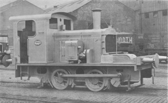
Garden Railway Specialists with money which was raised by my colleagues as a semi-retirement present. I have long coveted this kit and many moons ago I was fortunate enough to purchase an LGB OHO loco (similar to Otto) for a very competitive price on eBay.

Disassembling OHO

My first task was to strip down OHO to reveal its chassis. Fortunately, LGB locos are usually held together with screws. Firstly, the screws holding the steps were removed:

 ........followed by the two screws under the front of the cab.......

 ..... and the two screws at the rear of the cab.

At the same time I also removed the couplings. Although these do not hold the parts of the loco together, I prefer to strip loco chassis down as much as I can.


The cab, simply lifts off the chassis.

Next, the boiler was tackled. The two large screws beneath the loco were removed........

.....followed by the two beside the cylinders.

This released the boiler, firebox and smokebox assembly, together with the lead weight. The chassis was now revealed in all its glory.

Constructing the kit
For me, the first stage of construction was the footplate. The GRS instructions are somewhat vague over the way in which the stepped footplate actually goes together and, in fact, I took three goes at it before I figured out what worked. The first step (in my final approach) was to glue the spacer across the front of the cab footplate - the piece across the gap in the middle was later removed to accommodate the LGB chassis.

The sides and the buffer beam were then attached to the front section of the footplate. (The buffer beam was later removed as I decided to reshape it and also to fit it around the coupling hook).

The two halves were then glued together and the sides added to the rear cab section. The whole thing was fitted over the chassis to check for clearances.

To allow the footplate to fit snugly, the cylinders were removed (two screws) and the mountings for these were cut down using a razor saw. 

As it turned out, I cut them down a little too enthusiastically and had to build them back up again with three laters of plasticard. If I was to do this again, I would be more measured in cutting down the cylinder mountings (ahh.... the benefit of hindsight!!).

At the same time I removed (with a razor saw) the mountings for the valve mechanisms from the ends of each slider.

 Next, came the interesting bit. I test fitted the cab to the footplate and removed a small cut-out from the front of the cab to allow it to fit over the chassis.

The boiler/saddle tank sections were superglued together (after some filing and sanding to remove the moulding blips).


The smokebox was then attached.

The superstructure was then test fitted on the footplate to check for clearances.......

..... and small cut-outs were removed from the rear of the smokebox and the front of the firebox to fit over the chassis.

Next, the whitemetal details were cleaned up with a file and glued into place with superglue. Again, the instructions are not too clear but hopefully most of the parts are more or less on the right place - though I think the firebox door is hung on the wrong side (ie it's upside down).

Similarly, the chimney, safety valves and whistle were added to the boiler and smokebox.At the same time, some filler was applied to fill some dints in the casting.

Having learned from previous experience (see How I made a GRS Peckett loco kit), that retro-fitting decoders is a pain in the proverbial, I drilled and filed out the back of the boiler........

.....to take a Massoth L (identical to an LGB) decoder....

Similarly, I decided it was time to work out where the weights would go. I cut OHO's weight into two segments (with a hacksaw and much grunting)...........

 ...... and positioned the larger chunk on a piece of plasticard inside the saddle tank (above the decoder) ........

....... and glued (with epoxy) the smaller chunk inside the firebox, leaving room beneath for access to the decoder when the whole lot is finally glued together. The larger chunk was expoxied to the sheet of plasticard.

To ensure that the handrails would be level, I carefully drew a line along the sides of the saddle tank by balancing a ruler atop another and drew a line.....

....then measured 10mm above this and drew another line. Two 2.2mm holes for the handrail knobs were drilled 10mm in from each end of the tanks.

...and the handrail knobs were then superglued in place, with a length of handrail loosely fitted to ensure they would line up.

Similarly, the handrails for the cab were fitted, 5mm in from the doorway.

The whitemetal fittings (sandboxes, springs and buffers) were glued to the footplate. The buffer beams having been shaped and glued in over the couplings.

Incidentally, the front coupling needed to be moved forward 12mm to protrude sufficiently. It was simply screwed into the mounting further forward.

The various parts of the loco were now effectively finished and ready for painting.
 Painting and finishing
Painting is my  least favourite part of the modelling process - to my mind, it offers the greatest potential for error and maybe even disaster. With this loco, I decided that I would paint the various parts separately before fitting them together. The interior of the cab needed to be painted first anyway as this would have been impossible once the model was completed.

Two coats of grey primer followed by two coats of matt black were applied to the firebox and can interior, using Halfords' rattle can aerosols.

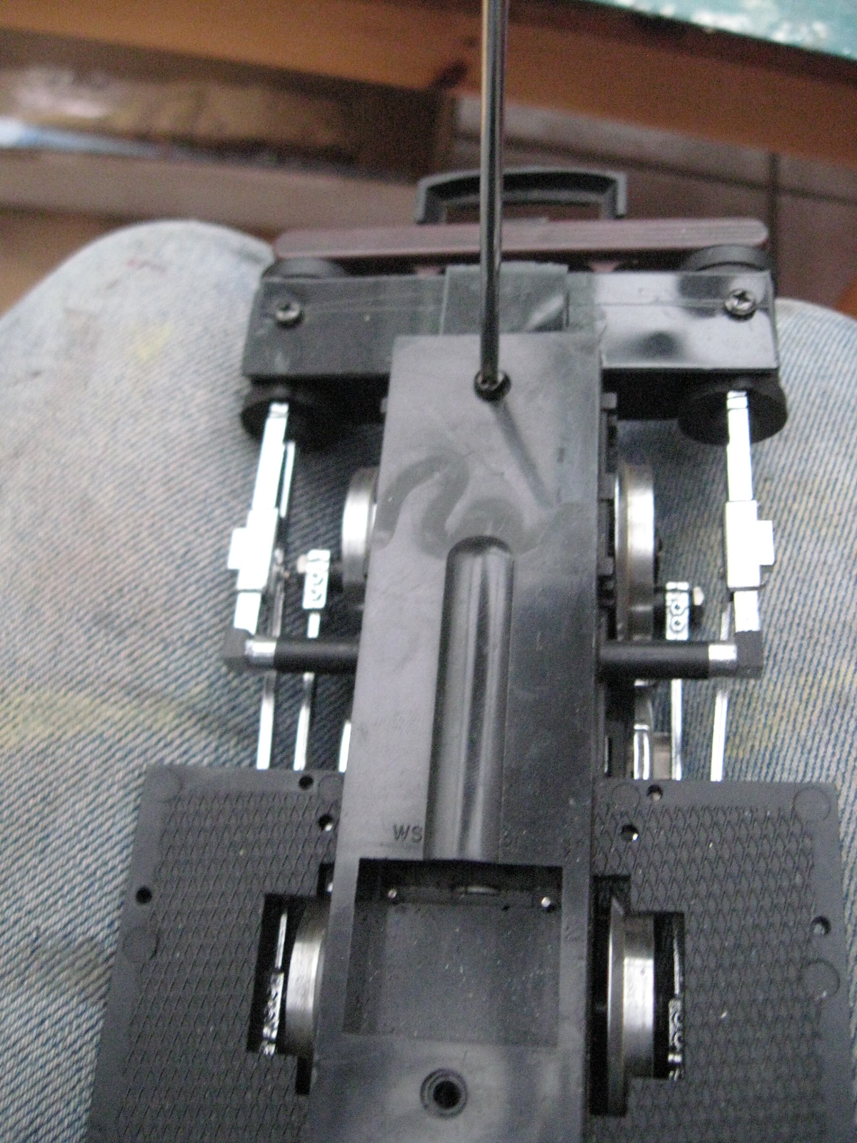
At the same time, I completely stripped down the chassis and gave that the same treatment. I did not want a red chassis.

The chassis was reassembled and the wheels painted with black acrylic and the motion picked out in red acrylic.


Everything was given a couple of coats of grey primer and then the cab and saddle tank were sprayed with Humbrol acrylic Brunswick Green and the footplate bruch painted matt black (acrylic) and the cab roof and smokebox sprayed with satin black (acrylic). The inside of the cab was painted cream and the buffer beams painted with Humbrol red enamels.


 Once the paint had hardened off, lining was applied using Trimline lining tape (see How I lined my locos with Trimline tape).


Name and number plates were glued on with Superglue


and waterslide transfers were applied to the buffer beams.


 The black areas were masked off and the everywhere else given a couple of coats of acrylic varnish to seal the lining and the transfers


A few minor details were added (eg a driver) or touched up (eg the buffers) and then the body was mated with the chassis.

A few more details need to be finished off (eg glazing the spectacles, some light weathering), but No. 3 is now ready to join the growing fleet.