This Blog describes the ongoing development of a 16mm scale 45mm gauge garden railway situated in the North West of England, UK from 2004 to the present day.
Several people have asked me how I created the animated clock which appears on the video 'A Day in the Life of Peckforton Station' and also how I synchronised it with the shots of trains arriving and departing.
Initially, filmed virtually every train movement which occurred at the station during a complete operating session, which actually took me around two days. Normally a full timetabled operating session takes about a day and a half but setting up the camera and occasionally having to repeat a train movement when, for example, the camera was too close to the track and got knocked over, meant that it took a bit longer than normal.
These individual clips were then edited together to make a first cut of the video using Corel VideoStudio X5 - but any video editing package could be used for this.
Once I was happy with the core video I then looked around on YouTube for an animated clock which I could superimpose on the main video. Fortunately, I found a neat little clock with a green screen background with open ended permission for non commercial use - https://www.youtube.com/watch?v=RIcSapc8CTE .
This was downloaded using Any Video Converter which is a freebie program which allows you to download Youtube videos and save them in virtually any format. I saved my download as a .wmv as I knew this would be readily compatible with VideoStudio.
Next, I consulted the timetable which I have created for my railway, which was based on the timetable for the Southwold Railway in 1923.
This enabled me to fix the departure times of all the trains from Peckforton station during a typical day. The approximate times for each of the other train movements (eg goods trains and mine trains) were then plotted and their times noted down. The clock video was then loaded into MediaPlayer and paused at the appropriate times. A screenshot was then taken of the screen (using the PrinScrkey) and then pasted into Paint, where it was cropped to show only the clock face with some of its green background.
Once all the 'stills' of frozen clocks had been taken, the clockface images were inserted into an overlay track in VideoStudio and then positioned in the bottom left hand corner of the video screen.
The green background was then made transparent by selecting the Chroma Key properties of the overlay image and using the eyedropper tool to choose the specific shade of green in the background.
This process was repeated for each of the clockface images.
The next stage of the process was to trim the animated clock video into chunks to fill the gaps between the stills with animations of the clock moving from the time shown on the first image to the time shown on the second image. This was a bit fiddly to ensure the trimmed video sections were accurate to the actual minute shown on each of the still images - but became quite repetitive amd hence easier over time.
These trimmed sections were then inserted into the overlay track between the two still images of the clockface. The final and quite time-consuming job was to finely adjust the size and position of each of the overlay images and animations to ensure they were in exactly the same position throughout the entire movie - even one pixel of misalignment showed up on the final movie (you may notice a couple of places where I still haven't got it quite right).
And that's basically all there was to it. The most difficult part conceptually was understanding how to make the green background transparent using the Chroma Key option but there are plenty of tutorials out there on the web showing how to do this in various video editing packages. The most time consuming part of the process in VideoStudio was making sure the clock face images and animations were precisely aligned with each other. Maybe on other editing packages this process is easier, but on VideoStudio it has to be done manually for each and every clip.
Quite a lot has happened since the last progress report. I have finished the ex-Davington Light Railway Manning Wardle 0-6-0ST and played host to a fellow modeller from Australia. I have also made a start on bashing a trio of Bachmann Jackson Sharp coaches into something vaguely resembling the balconied stock which ran on the Leek & Manifold Valley Light Railway. In addition, I have been experimenting with different forms of battery power, partly because the space inside the Manning Wardle was quite restricted. Finally, I have had a go at re-organising the storage in my workshop as things in there were becoming increasingly cluttered - and also I am starting to batten down the hatches in preparation for the onset of winter.
Manning Wardle 0-6-0ST
After a few trials and tribulations, I have at last completed the scratchbuild of my latest loco - an 0-6-0 saddle tank based (loosely) on those which Manning Wardle produced to run on the Davington Light Railway.
As this railway closed shortly after the end of World War I, I reasoned that one of the three locos was sold to the Peckforton Light Railway - the other two finding their way to Brazil (see How I constructed a Manning Wardle 0-6-0ST locomotive).
Although I have previously scratchbuilt three locomotives, made two from kits and kit-bashed a railbus, I found this particular build to be more demanding than any of the previous builds. This was partly because the extra work involved in making the saddle tank proved trickier than I expected, and also because I ran into a couple of unexpected snags along the way: the Revell filler which I used initially refused to adhere to the plasticard and was susceptible to cracking, and I discovered to my dismay that Evostik is an extremely powerful solvent of plasticard (see How I constructed a Manning Wardle 0-6-0ST locomotive).
Despite these trials and tribulations, I am very pleased with the end-result. Not only does she look quite appealing, I have discovered that the six-coupled wheelbase is extremely powerful when it comes to hauling excessive loads up my 1:40 gradients on the railway.
Here's a video of the loco's first run on the railway (before I had finished all the detailing).
An this video shows her phenomenal hauling capabilities. I certainly did not expect her to be quite so powerful.
I have been really impressed with this loco's slow-running abilities and her responsiveness to the Deltang receiver/controller. Given this and her hauling capability, I anticipate she will become the preferred loco for freight duties on the railway.
Running sessions
With the mild weather in September and the early part of October, there has been plenty of opportunity for me to run trains out in the garden. A few shots taken during one of the operating sessions to show how the railway and its stock are developing.......
Wynford sets off with a train of full ore wagons from the copper mine sidings
She traverses the recently relaid track on the approach to Beeston Castle.
At Beeston Castle, Loco No. 4 Bulkeley (former Southwold No. 4 Wenhaston) passes with the mid morning Down passenger train
The mid-morning Down passenger approaches Bulkeley as the Down pick-up goods approaches Beeston Market
The Down pickup goods coasting beside the River Gowy on the approach to Peckforton with Loco No.5 Tarporley
The Down pick-up goods leaving Peckforton and approaching the mill siding where she will exchange wagons
The Down pickup goods pulls into Bulkeley as the noontime Up passenger waits to depart.
The noontime Up passenger arrives as Beeston Market
The mid afternoon passenger about to depart Beeston Market as the Up pickup goods arrives
Meanwhile, skips are shunted at the Copper Mine.
Australian visitor
For some time, I've been corresponding with a fellow modeller in Australia, mostly picking his brains on radio control and how to wire up and program Picaxe microchips for the operation of signals and pointwork (see Progress Reports 52 and 53). The website for Greg's own garden railway, The Sandstone and Termite, is packed with useful information and ideas and well worth a visit. When he expressed a desire to revisit the UK to travel on the Welsh narrow gauge railways, I offered my services as a local guide. Earlier this month, Greg and Pauline came over for a couple of weeks and spent around a week exploring the locality of Cheshire and another week in Wales. He risked x-ray machines and border controls to bring one of his locos with him, Nick, a freelance railbus. Over the course of his visit we found time for three running sessions as the weather was particularly kind to us.
Sandstone & Termite Railway railcar Nick shunting at Beeston Market
Nick makes an inaugural run down the line, past the Copper Mine
Old and new railbuses are compared at Peckforton
Nick braves the undergrowth between Bulkeley and Peckforton
On light freight duties beside the River Gowy
Beside the Gowy on passenger duties
The two railcars on night duties at Bulkeley station
Greg was pleasantly surprised to find that the weather in the UK in October can actually sometimes be clement. Here we see our esteemed visitor, sporting his Sandstone & Termite Railway tee-shirt, assuming responsibilities as Chief Controller at Beeston Market.
Despite a few early teething troubles, everything on the railway performed well. I'm sure there is a Law of Garden Railway Modelling which says that the moment a visitor arrives, anything that can go wrong will go wrong - and for a while this seemed to be the case. Thankfully, this did not persist for the entire two weeks!
Bachmann Jackson Sharp to Leek & Manifold(ish) coach bash
The passenger coaches which the line presently possesses (see How I constructed coaches from Maddison kits) perform their function very well and although there are only three, this mirrors the level of coaching stock for many narrow gauge railways in the UK (see How much stock did UK narrow gauge railways have?). However, to enhance the railway's operational potential, I have for a while considered acquiring at least another three coaches to allow two passenger trains to operate at times of additional demand (eg market days, special excursion trains). Before constructing the Maddision coaches, I used to run a couple of Bachmann Jackson Sharp balconied coaches which, despite their smaller scale, represented for me something vaguely resembling the stock used by the Leek & Manifold and the Southwold Railways(seeProgress Report 11)
A passenger train on the railway in 2008
For at least five years these coaches have languished in a drawer in my workshop until I came across some drawings of the L&M coaches and did a few quick calculations. I realised that I could produce a foreshortened representation of these coaches if I narrowed the windows slightly and lengthened the balconies a little.
The bodies needed to be increased slightly in height but as the clerestories were going to be removed this would not actually increase their overall height. I already know that these coaches have no problem tackling the tight curves on my railway and so have pressed ahead with the 'modification' of the first coach.
I am presently about halfway through bashing this coach and am using this as a learning-curve for bashing the other two. Two coaches will be opens and the other will be a brake end.
Battery power
Although I am relatively new to the world of battery power and radio control I have already accumulated a fair amount of experience in constructing battery powered locomotives and experimenting with various combinations of radio control devices (see An Introduction to battery power and radio control). Given their power-to-weight ratio, I am now convinced that li-ion batteries are the most cost effective and efficient way of powering garden railway locomotives. There are some risks associated with this form of technology (as witnessed by recent fires aboard aircraft and the occasional horror story about mobile phones bursting into flames), but given that most portable technology is now powered by li-ion batteries (including the laptop computer on which I am writing this blog), it would seem that the vast majority of li-ion batteries are sufficiently reliable to be considered for this application. However, I still have a couple of locos which are powered by NiMh batteries but have recognised that there are better options than normal off-the-shelf rechargeable batteries.
18650 Li-ion
As mentioned above, one of the difficulties I encountered with modelling
the Manning Wardle saddle tank loco (see How I constructed a Manning Wardle 0-6-0ST loco) was finding room inside for the
batteries. My usual source of power; the 12v blue lithium-ion batteries
intended for CCTV applications (seeAn Introduction to Battery Power and radio control)
were too large to fit into the confined space ......
........ and there was no way I
would have been able to squeeze ten NiHh 1.2v AA (or even AAA) batteries
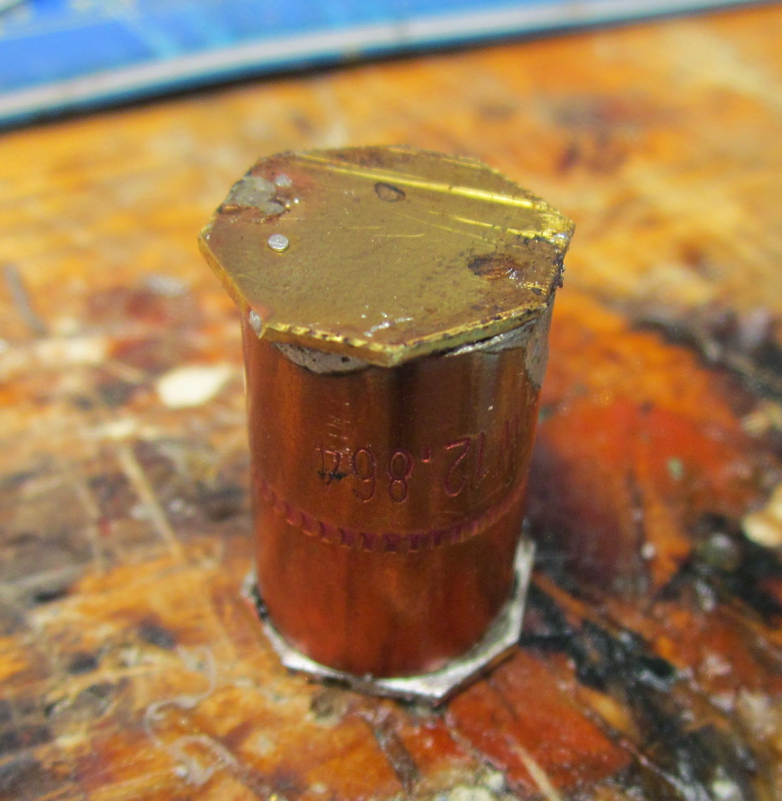
in. After discussing various options with fellow modellers on the G Scale Central forum, I invested in some 18650 style 3.7v li-ion batteries. These cylindrical batteries are what many laptop computers use inside their battery packs and so there is a ready supply and a wide variety of types available. However, even in my limited experience, I have learned that you do tend to get what you pay for. Some of the cheaper, so-called high capacity 18650 batteries do not live up to expectations. The first set of these batteries I bought for a modest sum claimed to be 5000mAh (ie they would power a motor running at 1amp (ie 1000mA) for five hours.
When I did a discharge test on them, they averaged-out at 1.5Ah (ie 1500mAh) - considerably lower than that claimed. I then opted for some more expensive, branded (Samsung), batteries from a reputable supplier. These were labelled as 3100mAh and when tested were not far short of that capacity.
Another aspect which I have appreciated needs to be taken into account is whether the batteries are 'protected'. Li-ion batteries can be damaged, or worse still can catch fire, if they are under- or over-charged. To ensure this doesn't happen, protected batteries include a small circuit board which cuts off the charge or stops the battery from discharging if the voltages fall outside the accepted safe levels. The 18650 batteries I am using in my latest loco are unprotected and so I make sure that I charge them carefully using a balance charger and regularly check their discharge with a small battery checker.
This plugs into the balance charge socket and the LEDs show green if the batteries are OK and turn to red (and the buzzer sounds) if they drop below 3.3v. When running, I leave it attached to my loco but remove it when I store the loco.
NiMh low self-discharge
One of the most irritating aspects of normal NiMh rechargeable batteries is the speed with which they lose their charge when not being used. Many's the time I've wanted to have a quick impromptu operating session and been unable to use the locos powered by NiMh batteries because they've needed charging. My Australian friend alerted me to low selfdischarge NiMh AA batteries which can be obtained from Hobbyking for quite reasonable prices.
These batteries seem to be holding their charge very well. I've detected very little drop in power even after a loco has been in storage for a couple of weeks.
Workshop revamp
Partly inspired by the arrival of my house guest from the colonies, I felt it was time to re-organise the storage in my workshop. Some of the odds and ends which I had accumulated had outgrown the space allotted to them and there were times when I struggled to lay hands on a material or component needed during construction. I had previously organised some of my tools by fashioning a rack .......
...... and so now invested in some storage containers from our local pound shop ..........
...... and constructed a storage unit for larger and longer materials.
Previously, trying to use the conservatory for its intended purpose of sitting, chatting and admiring the garden had not been a pleasant experience. Now it is at least possible.
Preparing for winter
The station buildings have now been brought inside. Previously I had left these out throughout the year but at the start of this year I had realised how dilapidated they had become.
After spending some time re-gluing and repainting them (see Progress Report 52), I decided this was one job which could be avoided, or at least postponed, by storing the buildings inside during the worst weather. If I do need to have some buildings in place during the winter, to take pictures or video, then it takes only a few minutes to re-install them.
To Do List
There is always something which needs to be done on a garden railway - which is really what makes the hobby so interesting. My present and ongoing list comprises:
After converting my kitbuilt Barclay 2-6-0T loco from track power to radio controlled battery power Progress Report 51), I had decided that I did not really need any more locos - until, that is, I happened to find a secondhand copy of the Oakwood Press booklet about the Davington Light Railway. This short-lived metre gauge railway ran three miles from Faversham to the explosives factories in Davington. It was established in 1916 to transport workers to and from the factories during the First World War. The mainline section of the line was operated by three Manning Wardle 0-6-0ST locomotives. When the war ended the railway was closed and the locomotives were returned to the manufacturers and then shipped to the Donna Teresa Christina Railway in Brazil. Two have been preserved; one is at a railway museum at Tubarao and the other is displayed on a plinth outside the works at Criciuma.
I was captivated by the design of these locos and decided that one would make an interesting and unusual addition to my railway. A quick measurement of the Piko 0-6-0 motor block (obtained from G-bits) confirmed that it would be roughly appropriate for a 1:20 model.
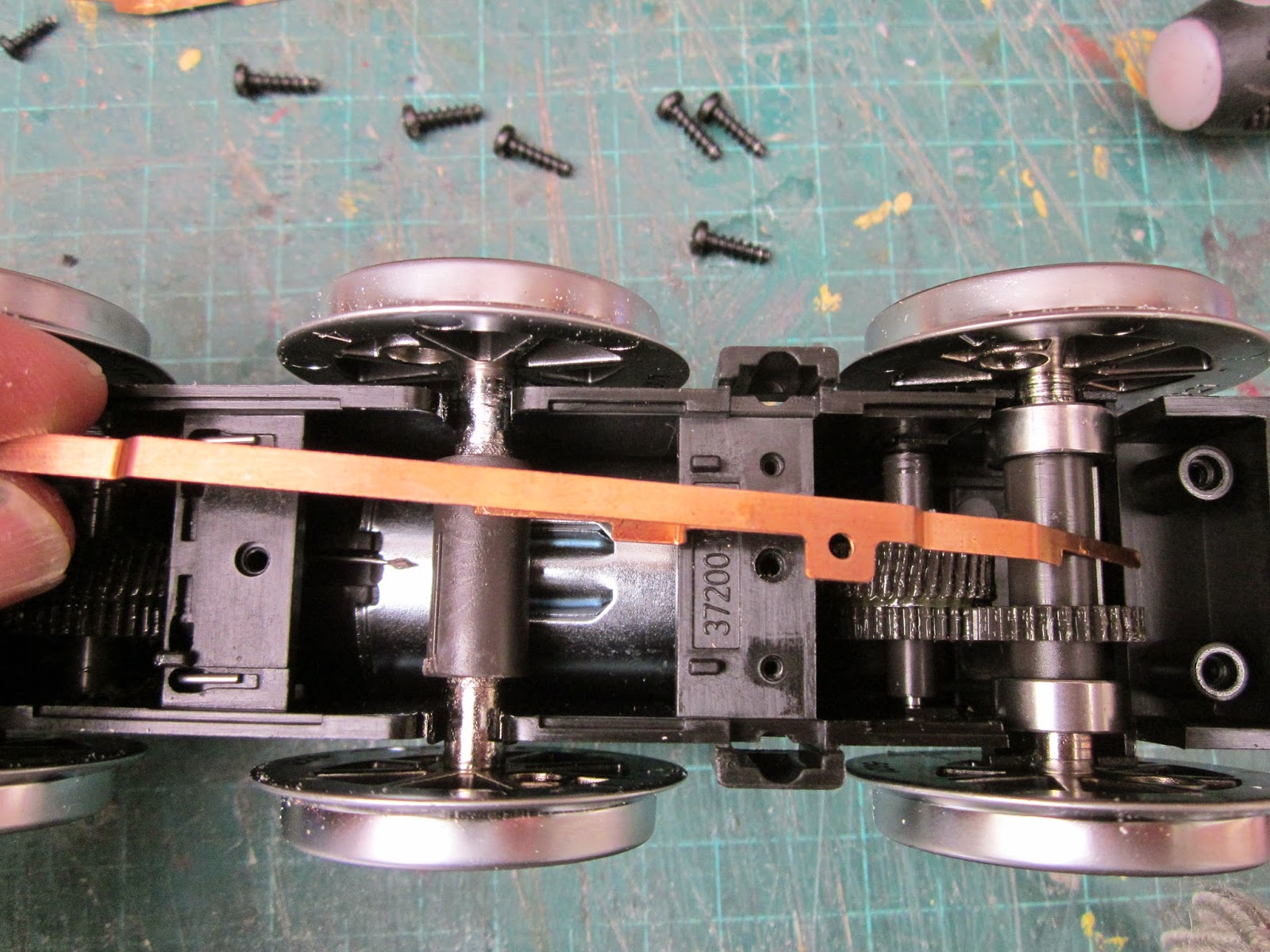
The first job was to remove the electrical pick-ups as I will be making a battery powered, radio controlled model. The six screws holding the baseplate in place were unscrewed and the base plate removed ........
..... exposing the pick-up contacts.
The small self-tapping screws were removed from the copper contact strips allowing these and the skates to be detached.
The two L-shaped steel contact wires were then removed and the baseplate was screwed back into place.
Attention was now turned to the body. I usually start by cutting out the running/footplate as this forms the basis for the model and will also dictate how the body will fit over the chassis. A 272mm x 94mm piece of 2mm thick plasticard was cut out and a 37mm x 110mm hole cut into the centre - 74mm from the front end of the running plate.
This was then placed over the motor block to check clearances.
I then searched the garage for a piece of pipe or a cylindrical container of the right diameter (46mm) for the boiler. A tube of sealant proved to be about right and so a piece of 1.5mm plasticard was cut to length (122mm) and wrapped around the tube, being held in place with cable ties. The whole lot was then immersed in boiling water and left for around 15 minutes.
I was now ready for the next stage of construction which was going to take place whilst on holiday in France. Fortunately, my very tolerant partner is quite happy for me to take some modelling materials with me to the cottage which we rent in France where I have also accumulated a modest collection of modelling equipment - a steel rule, a cutting board, a craft knife, some needle files and tubes of liquid plastic adhesive and Superglue. I find this is sufficient for most plasticard modelling projects (I've now made five models in this way - a crane wagon, two cattle trucks and a locomotive)
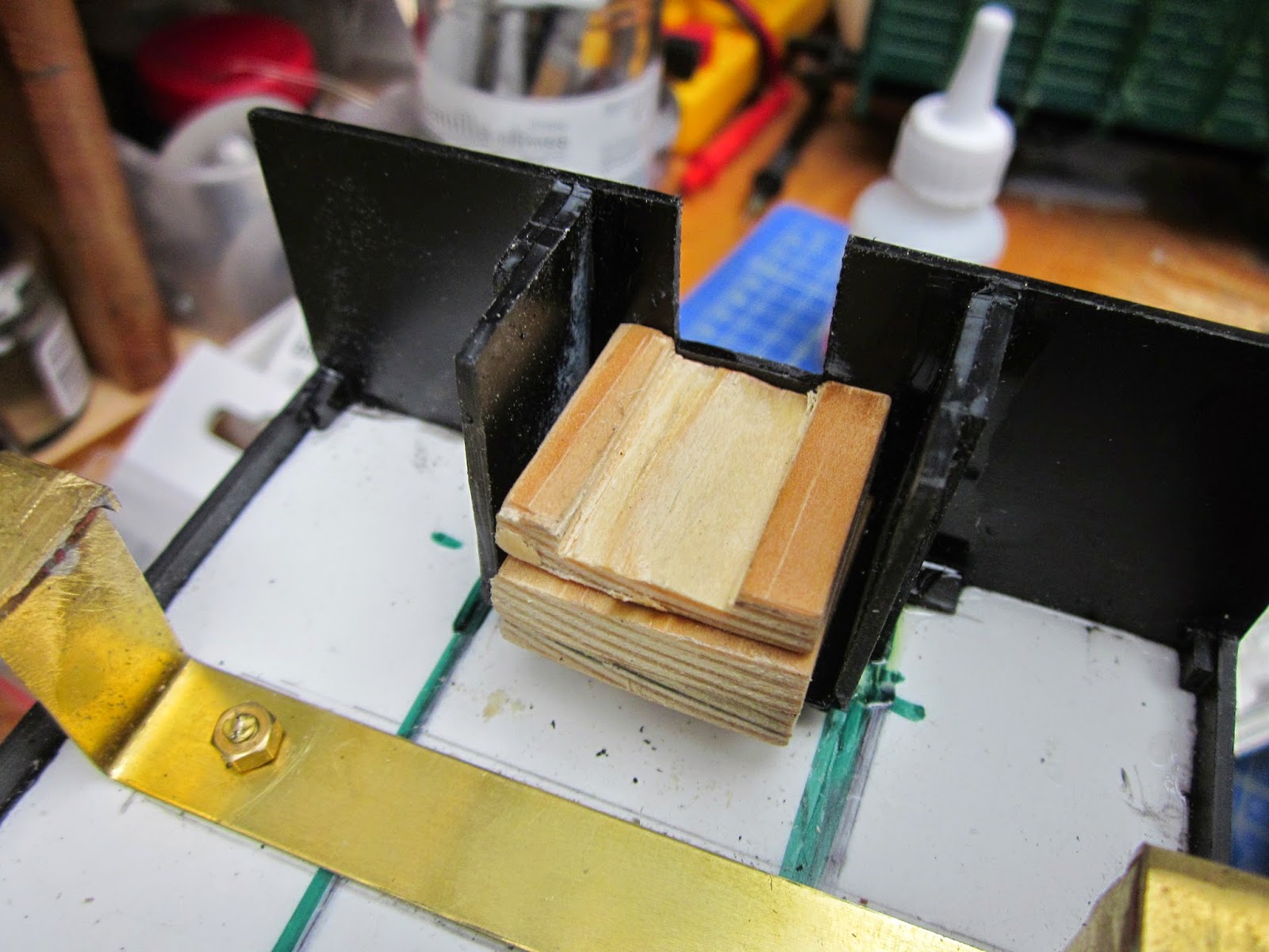
The cab was modelled next. Two ends, 86mm x 94mm were cut from 1.5mm thick plasticard, and 18mm diameter spectacles cut out with centres 18mm from each edge and 18mm from the base. The top edge was curved off using a large casserole dish as the template. The holes were cut out roughly initially and then smoothed off with a needle file.
Two sides were then cut out, 102mm x 92mm. There were then shaped to give a width of 83mm for the upper edge of the cab and a width of 95mm to the lower edge. The coal bunker was cut to shape to a height of 45mm from the base. The cab door was also cut out, 25mm wide at the base and 56mm wide at the top, with a leading edge of width 22mm and a 'lintel' of depth 7mm.
A 52mm diameter hole was cut into the front of the cab rising to 57mm above the lower edge and opening out to 45mm at the base. This was to accommodate the firebox.
Two end-pieces for the firebox were cut out from 1.5mm thick plasticard, to match the dimensions of the hole cut in the above cab front. In one, a rectangular access hole was cut.
The other was clad in whitemetal backhead detail fittings from GRS.
A 46mm wide strip of 0.5mm thick plasticard was glued to the front piece of the firebox, with clothes pegs to hold it in place until the glue hardened. This was deliberately cut to be longer than required so it could be trimmed to fit later.
A few offcuts of 1.5mm thick plasticard were trimmed to roughly 43mm x 5mm. The length was important but the width was dependent on what off-cuts I had available.
Once the glue had set on the firebox, the wrapper was trimmed off in line with the base of the front piece.
..... and five of the 1.5mm strips were glued inside the wrapper to give it some stiffness.
The back of the firebox was then glued to the open end of the firebox.
While the glue was setting on the firebox, I fixed the cab on to the footplate and then the completed firebox unit was inserted into the opening at the front of the cab.
I decided to leave it unglued at this stage so the various sections
would be easier to paint and also it would be easier to insert the
batteries and electronics at a later stage.
Attention was now turned to the smokebox and saddle tank. The front and back of the smokebox were trimmed to a circle of 46mm diameter and flared down to a flat base of width 33mm from 1.5mm thick plasticard. A further circular piece 46mm in diameter was cut out and filed to shape (although this piece was not needed as it turned-out). The front and rear of the saddle tank were also cut out - the rear piece rising 9mm above the height of the firebox (the uppermost piece shown below) and the front piece rising 20mm above the height of the smokebox. The width of the saddle tank was 67mm and the height of the sides were 34mm. The curve of the upper edge of the tank falling to be in line with the upper edge of the firebox.
The rear of the saddle tank was then fixed to the firebox ......
The smokebox was constructed with a 24mm wide strip of 0.5mm thick plasticard covering a 49mm long section of the 46mm diameter tube formed above. The front of the saddle was then glued on behind the smokebox.
The sides, base and top of the saddle tank were then glued on (97mm long) and the various joints and gaps were filled with plastic filler.
The bodywork was then check for fit and clearances.
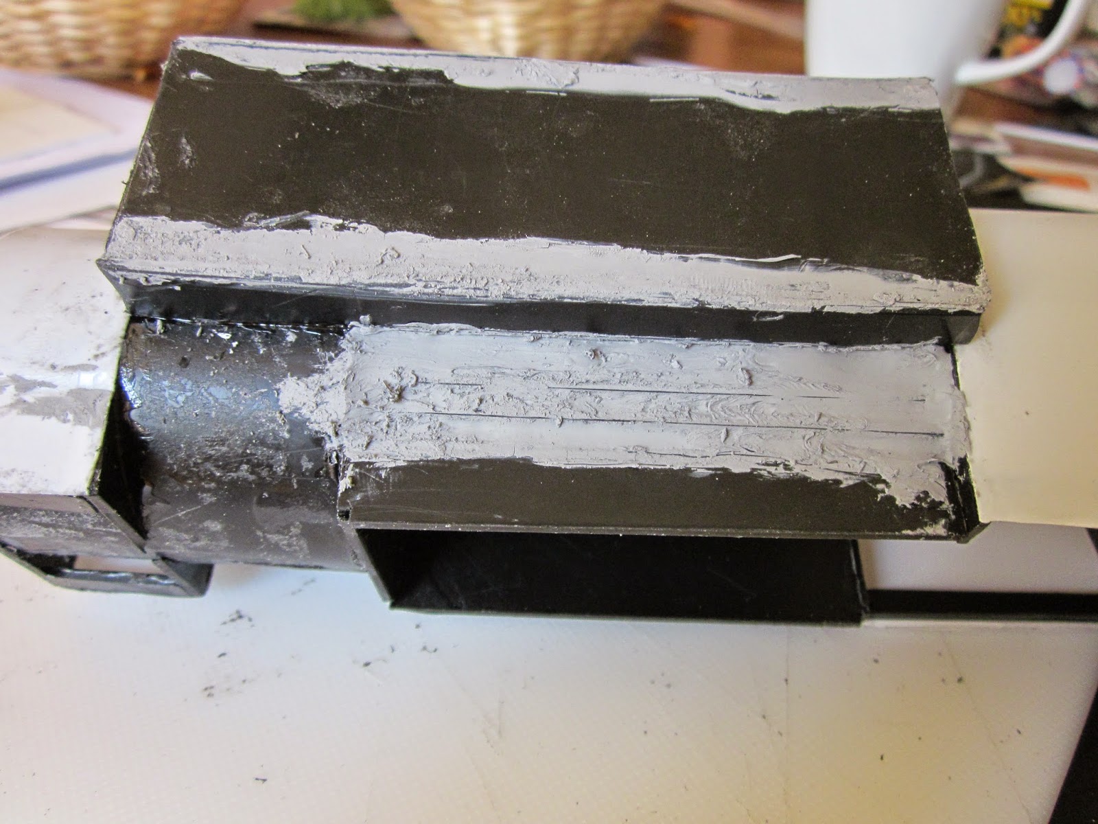
The gap beneath the tank was filled in with a box made of appropriate lengths of plasticard. Revell plastic filler was applied to try to represent the visible section of boiler beneath the tank.
However, once dry, the filler began to crack and peel off .........
...... and so it was removed and some strips of plasticard offcuts were applied to build up the profile .....
and a strip of 0.5mm thick plasticard was glued over them. I could have continued the tubular boiler along the entire length beneath the tank but as my loco will be battery powered I was anxious to create as much uncluttered space in the tanks as possible. If I had been constructing a track-powered loco there would have been less need for this additional work.
A piece of 1.5mm thick plasticard was cut to 83mm x 43mm and a couple of sliding doors were fashioned from some offcuts. Another piece of 1.5mm plasticard was cut to 83mm x 12mm to act as a cover.
These pieces were then glued into the inside of the cab at the rear to act as access to the coal bunker.
The brake handle was made from the top 30mm of a GRS whitemetal casting which was inserted into a hole in the top of the bunker cover at an angle of around 40 degrees off the vertical.
Two pieces of 83mm wide 1.5mm thick plasticard were glued to form the angled back of the coal bunker.
Three 83mm x 7mm strips of 1.5mm thick plasticard were shaped to the profile of the cab roof - two having arcs removed from their lower edges to clear the spectacles.
These were glued to a 96mm x 92mm piece of 1.5mm thick plasticard to form the roof for the cab. I prefer to have the roofs of my locos removable to facilitate painting of the inside of the cab and to enable me to add finer details to the cab over time.
The sandboxes either side of the smokebox were tackled next. For each box, two sides (18mm x 13mm), two ends (10mm x 13mm) and a top and bottom (19mm x 21mm) were cut from 1.5mm thick plasticard.
These were glued together to form open topped boxes......
...... to which the lid was added and when the glue had set, the rough edges were filed and sanded.
The caps were made from a couple of slices off the barrel of a cheap ball-point pen which were glued into place ........
........ and capped with filler which was then sanded to provide a domed shape .....
A couple of copper-plated panel pins were then pushed into holes drilled through the middle of the caps to represent the knobs.
On return to the UK from France, the body was united with the chassis to check clearances and to ensure the build could progress without any major adjustments.
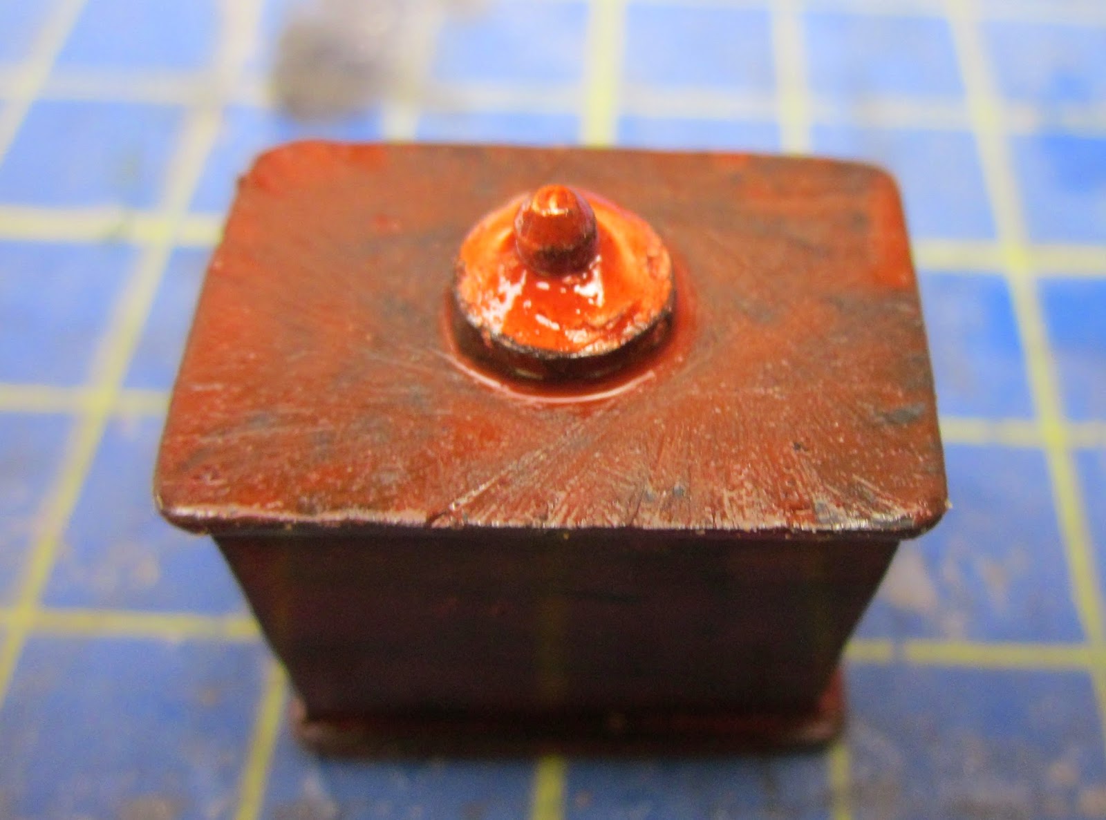
A whitemetal tank filler cap was purchased from Garden Railway Specialists (GRS) and attached to the middle of the saddle tank.
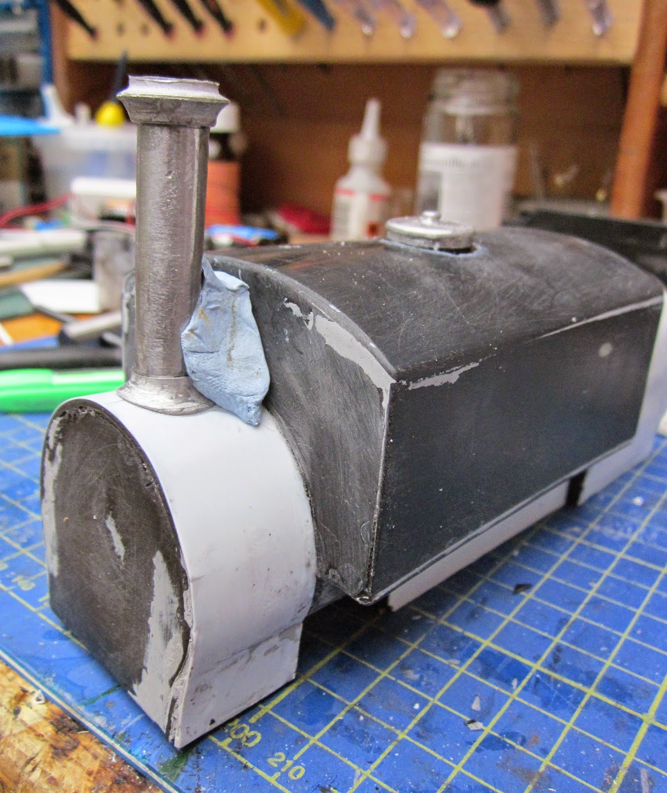
After searching for something suitable, a board-marker of the correct outside diameter (15.8mm) was found to form the basis for the steam tower over the firebox.
A 30mm length was cut - 22mm to form the tower and an additional 8mm to enable it to be secured to the top of the firebox.
After rejecting the idea of using plasticard tubes for the safety valves (largely because I had none of the correct diameter to hand), I chanced upon a plastic model motor cycle in my local 50p shop.
The hand-grips looked ideal and so were duly snipped off.
A 45mm x 25mm piece of 2mm thick plasticard was glued inside the top of the firebox to provide a firm foundation for the tower.
A 16mm diameter hole was then drilled into the top of the firebox and the tower glued into the hole.
A piece of 2mm thick plasticard was glued to the top of the tower and
then filed to form a flat-topped dome. The hand-grips were then glued to
this with the thread of a self-tap screw glued between to represent the
sprint. A small piece of brass strip was then glued across the top once
a slot had been sawn into the tops of the valves and the screw.
A whitemetal casting for the chimney was purchased from GRS and cut to a length of 44mm. The castings were filed and sanded to remove unwanted flash and to tidy up a couple of flaws.
Having used these castings before, I have discovered that the most reliable way of gluing them together is to slot the chimney into the upper rim and then apply superglue to the joints (making sure that as little as possible flows down on the the surface below - otherwise you need to prise it off when dry).
A 4mm pilot hole was then drilled into the top of the smokebox and reamed out to 7mm (I find this more reliable than trying to drill a large hole which seems to wander off centre).
The base of the chimney was then superglued into place, checking to make sure it was central.
Once the glue on the upper part of the chimney had set, it was superglued to the base, with a dollop of Bluetak to hold it vertical until the glue set.
To mount the whistle beside the steam tower, two 1.5mm and one 3mm holes were drilled in an off-cut of 1mm thick brass strip. The holes were roughly 5mm apart.
Into the smaller holes, two short pieces of 1.5mm diameter brass rod were soldered (they were pushed into holes drilled into a piece of ply beneath the brass strip to hold them steady - I haven't yet figured out how to create asbestos fingers!).
The brass strip was then trimmed to shape around the holes and pegs and the soldering tidied up with a file.
The bracket was then bent to shape and a couple of holes drilled in the front of the cab to take the pegs. The bracket was then superglued into the holes.
A Roundhouse brass whistle was then screwed to the bracket. Cast whitemetal spectacle surrounds (from GRS) were then superglued around the spectacles. I had considered filing out the windows so they could be inserted as I have done with previous models but, on this occasion, I left them proud.
With most of the superstructure now completed (I was still awaiting delivery of a smokebox door casting from GRS), I decided to turn my attention to the motion.
The chassis
The first job was to extend the chassis to match the length of the bodywork. A 65mm x 95mm piece of 0.7mm thick brass sheet was cut out and with two 15mm x 30mm rectangles were cut from two corners. The brass was then bent to shape, as shown below.
Two 4mm diameter holes were then drilled in the upper tail to coincide with the screws on the motor block, and the chassis extension was screwed on the motor block, as shown.
A similar piece (75mm x 95mm) was shaped and fixed to the rear end of the motor block.
The motion
The coupling rods were the most obvious place to start. Two pieces of 6mm wide x ??mm thick brass strip were marked out with centres at 57mm and 115mm with 5mm spare at each end. Parallel lines were also marked 1.5mm from each edge.
3mm diameter holes were drilled at the centre markings which were then made slightly oval with a file to allow for any minor discrepancies in my marking-out and drilling.
After being tested on the chassis to ensure they would work, the sides of the rods were filed to shape, leaving bosses at each of the bearings.
After some experimentation, I found that 3mm diameter bolts inserted behind the wheels would fit into the rather large holes for the coupling rods and a nut could be tightened to hold each in place. The coupling rods were then slid over these crank pins with plain washers either side and a nyloc nut screwed over the top, leaving some slack for movement..
To ensure the wheels were perfectly meshed on the gears, the chassis was then powered up at a slow speed, with the wheel covers removed. I find this enables the gears to float naturally into their appropriate places on the worms.
Two 12mm diameter top-feed straight copper plumbing pipe unions were purchased. The unions were placed on a piece of 1mm thick brass and drawn round with a scriber. These end-pieces were then roughly trimmed to shape ........
...... and then soldered on to the copper unions.
The end-caps were then filed to shape.
Three 2mm diameter holes were drilled into the end-pieces - one in the centre and the other two 3.5mm out from the centre.
A piece of 2mm OD brass tube was then soldered into the middle hole and two lengths of 1.5mm square tube were soldered into the outer two holes on each cylinder. The centre tube was trimmed to leave 6mm protruding while the square tubes were trimmed flush with one end and then to a length of 40mm at the other end.
Two pieces of 1.5mm thick plasticard were superglued to the ends of the cylinders with holes drilled to match the slide rods and centre tube.
A strip of 0.5mm thick plasticard was wrapped around each cylinder and superglued into place.
To make the crosshead, two 10mm long pieces of brass were trimmed from a piece of 6mm wide and 1mm thick brass strip. A 6mm square was also cut out together with another from 0.5mm thick brass strip. Each piece had a 2mm diameter hole drilled in the centre (NB - the holes were drilled in the strips before the pieces were cut off to make holding the brass easier while the holes were being drilled). The pieces were all tinned with solder.
They were all threaded over a wooden cocktail stick inserted into an off-cut of plywood and head applied from the soldering iron to fuse the pieces together.
A 1mm diameter hole was then carefully drilled into one side of the crosshead and a length of 1mm diameter brass rod soldered into the hole taking care to apply the heat quickly to avoid unsoldering the crosshead. I did consider shaping the crosshead but decided to leave well alone.
Two connecting-rods were drilled, cut-out and shaped from 1.5mm thick and 6mm wide brass strip. The holes were 64mm apart and 5mm from each end - one hole was 3mm diameter and the other 2mm in diameter.
A 2mm countersunk screw and plain washer was soldered to the crosshead, acting as a pivot for the connecting rod.
The screw was then snipped off and filed flat.
Eight Cambrian cosmetic plastic bolt-heads were then glued on to the ends of each cylinders.
To mount the cylinders, I realised I needed to make a bracket to ensure they would give sufficient clearance for the wheels and the motion. A piece of 110mm x 105mm x 1.5mm thick brass sheet was marked and cut-out as shown
This was folded and screwed into place on the motor block in place of the previous extension piece (another example of my lack of forward planning).
The cylinders were then attached to the bracket with a self-tapping screw. The ends of the slide bars were soldered to the hangers which had been folded to provide a 2mm lip.
The connecting rod was then attached under the nyloc nut on the centre crankpin and the body positioned to check clearances. The batteries and receiver were temporarily installed to allow the motion to be test-run. A few tweaks were required to the slidebars and crosshead on one side to prevent binding but otherwise, the system worked well. At this stage the piston rods and crank pins were left over-length to allow for fine-tuning. Once the motion was checked, these were filed to a more appropriate length.
Two pieces of 1.5mm thick sheet were trimmed to 50mm x 12mm. Two slots were cut, 5mm deep and 15mm apart, 5mm from one end.
After scoring between the two cuts, the intervening section was worried and snapped off with a pair of pliers.
This new bracket was then bent over and soldered into place behind the slide-rod support. In hindsight, I should have included these pieces when shaping the main bracket to support the cylinders - but as already mentioned, forward planning has never been one of my strong-points.
At this point the motion and exposed parts of the chassis were given a coat of red primer and then the frames painted with black acrylic. The gaps between the ends of the chassis and the buffer beams were filled with 2mm thick rectangular off-cuts which were glued to the underside of the running plate behind the buffer beams.
At the rear, an additional layer of plasticard was added inside the spaces .....
.... to hold the chassis in place. At the front, a 4mm hole was drilled in the chassis and a self-tapping screw driven into the underside of the body beneath the smokebox to fix the chassis to the body.
The inside of the cab was painted in cream and dark brown
..... and then the two halves of the body were glued together.
This enabled the covers on either side of the firebox to be completed. Two pieces of 1.5mm thick plasticard were cut to 44mm x 15mm and 44mm x 20mm. The larger piece was trimmed to mirror the shape of the firebox sides. These pieces were glued together and a couple of strips of 2mm thick plasticard glued behind the joint.
The leading edge was then filed to form a curve.
End-caps were then cut and added to one end of each cover.
A strip of 0.5mm thick plasticard was then glued to the outside of the covers and when the glue had set, trimmed to shape.
The covers were then glued into place (and any gaps filled with White Putty).
A 120mm x 12mm strip of 1mm thick brass was cut and then bent to shape, at 10mm and 34mm from each end.
Two 10mm x 16mm strips of brass were cut and 2mm of each end bent upwards.
These were then soldered to the underside of each end of the longer strip and then tidied up with a file.
Two 4mm holes were drilled in the longer stretch and equivalent holes drilled and countersunk in the floor of the cab.
4mm countersunk bolts and nuts were then used to fix the steps into place .....
...... directly below the entrance to the cab.
3mm diameter holes were drilled 5mm from each edge at the corners of the saddle tank and short handrail knobs (from GRS) glued into place.
As the casting for the smokebox door still hadn't arrived, I searched from something domed of the right diameter. In my local pound shop I found a pack of four castors with domed wheels of exactly the correct diameter (38mm).
One wheel was removed from its axle ....
.... and carefully trimmed with a razor-saw to provide a domed smokebox door 2mm thick.
Two 25mm x 4mm strips of 1.5mm plasticard and a short length of 1.5mm diameter brass rod were attached to make the hinge, and the smokebox door was attached to the front of smokebox.
Mounting the couplings
I am still using LGB couplings for all my rolling stock, primarily because they work and are reliable - and also because it would be expensive to replace them. Three 24mm x 24mm blocks of stripwood were glued behind the rear buffer beam into which a slot had been cut at the appropriate height.
Some fine tuning was required (ie by filing the wooden block) to get the coupling at the right height before it was then screwed to the block.
For the front coupling, a bracket was bent up from an offcut of 1.5mm thick brass sheet (87mm x 35mm)
This was bolted to the chassis member to sit behind the front buffer beam. Again,, if I had planned ahead, this could have been incorporated into the front extension to the motor block.
Cambrian cosmetic rivet heads were then added to the buffer beams.
Painting
Before painting, any obvious cracks and crevices were filled with White Putty filler and then sanded smooth.
The inside of the cab was then masked with masking tape .......
....... and the body was given a couple of coats of Halfords grey primer from an aerosol rattle can.
Once the primer had dried, the bodywork was mounted on the chassis and carefully studied.
I find that primer tends to show up any inconsistencies, for example, in this case the Revell filler had cracked and peeled and needed replacement.
The dint, cracks and crevices were filled and then the whole body was rubbed down again with fine wet and dry emery paper and the body given another two coats of primer.
This was then gently rubbed down again, before the body was given three coats of Halfords Rover Brooklands Green from a touch-up spray aerosol and once dry, the masking was removed.
The running plate was given a couple of coats of black acrylic, as were the footplate steps .......
....... chimney and smokebox.
The cylinders were also painted Brooklands Green and the coupling rods and connecting rods were hand-painted red with Plasticote Insignia Red. The buffer beams were also given a couple of coats of Insignia Red.
After the bodywork had been lightly rubbed down, the cab, running plate and smokebox was then masked again and the body given a couple of coats of gloss varnish.
Detailing
Two lengths of brass rod were inserted in the handrail knobs on top of the saddle tank and fixed in place with superglue.
The front handrail was bent from a piece of 1.5mm diameter brass rod, with two small pieces of brass tubing and two 10BA washers threaded on to the ends ......
...... before a couple of holes were drilled into the front of the tank and the handrail was superglued into place.
Four handrail knob castings (from GRS) were primed and painted green before being attached to the sides of the cab with 1.5mm holes drilled to take the tabs.
Four
lengths of 1.5mm diameter brass rod were cut and bent to shape,
....before
being inserted into the handrail knobs and holes drilled in the
footplate.
The 70mm long reversing rod was cut to shape from a piece of 1mm thick brass strip - 4mm wide at one end, tapering to 2mm wide at the other. A 1mm diameter hole was drilled in narrower end, 1.5mm from the end. Another piece of 1mm brass strip was cut to length, 10mm long, 3mm wide, tapering to 2mm wide at the other end. A 1mm hole was drilled 1.5mm from the narrow end. A domed brass pin was then soldered into the two holes to join the two pieces together. The assembly was then primed with red oxide primer and then given a couple of coats of Plasticote Insignia Red.
The assembly was then fitted into place beneath the tank.
To make the sander operating linkage, two pieces of 1.5mm square tube were cut to 130mm and 35mm. 1mm slots were cut into one end of the longer piece and both ends of the shorter piece. A bell-crank was cut from 1mm thick brass strip, 6mm x 4mm, with 1mm holes drilled into the ends and middle, 1mm holes were also drilled into the ends of the tubes.
The bell-crank was then soldered to the two square tubes with dome headed brass pins through the holes.
Another piece of 1mm brass strip was cut to 4mm x 1.5mm and slotted into the other end of the shorter piece of square tube and soldered into place with a brass pin. The whole assembly was then given a coat of primer and a couple of coats of Rover Brooklands Green ........
.......... and once dry, fitted into place along the side of the tank.
The pipework for the injectors was made up from lengths of 13 amp copper wire stripped of insulation and various pieces of brass tube and brass rod. A 1.5mm diameter hole was drilled into the a piece of 2.2mm OD brass tube approximately 2mm from the end (I found filing a notch with a triangular file first helped to start the drill).
The tube was then cut to a length of 4mm and a piece of copper wire was then threaded through the hole.
Two 'collars' were cut from the tube - one 2mm long and the other 3mm long. These were threaded on to the wire and two 10BA washers were then threaded on top of the longer collar,
A 4mm length of 1.5mm OD brass tube was cut and a length of 1mm diameter brass rod inserted into it.
The various pieces were then threaded together and flooded with superglue. I had tried soldering but my skills were not sufficient to achieve the job neatly. I found that doing the gluing on a piece of paper meant that once the glue had set, the paper could be peeled off and the assembly tidied up with a file.
Once this assembly had dried a 3mm length of 2.2mm OD brass tube with a 1.5mm hole drilled through it was then threaded on to the 1.5mm OD tube and glued into place with an 8BA washer placed beneath. This again was flooded with superglue.
Once dry, the assemblies were then bent to shape and fitted on to the sides of the loco. A brass clack valve casting from GRS was glued to the boiler and connected to the system.
A small coil of 1mm brass rod was made by wrapping it around a nail, then removing and this was mounted beneath the whistle.
A piece of 1.5mm thick plasticard was cut to shape and glued into the bunker over the lead weights. This was then liberally coated with PVA and crushed coal sprinkled over.
At present, the cab detailing has been left fairly sparse, but over time more details will be added to enhance its appearance.
Weights
I have found with battery operated models there is often a fight for space with the electrics and the need to add weight to an otherwise lightweight body shell. This model has proven to be the most difficult so far to find sufficient space for weights.
I mostly use a roll of lead flashing to provide most of the weights for my locos. This provides me with strips of lead which can be trimmed to fit into most nooks and crannies. Two pieces, 90mm x 30mm were glued into the sides of the saddle tank ......
.... and another two pieces (55mm x 90mm) were glued into the top of the saddle tank.
Five pieces, 80mm x 35mm, were glued into the coal bunker and to equalise this, around 150g of .22 airgun pellets were ladled into the smokebox.
These, along with the other weights, were held in place with liberal amounts of Evostik Contact adhesive.
WARNING - DO NOT USE EVOSTIK!!
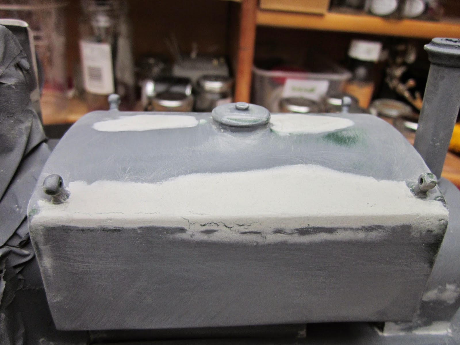
Previously, I have used Bostik Clear Adhesive to fix weights into place. I hadn't realised just how much stronger Evostik was as a solvent of styrene - until now! As can be seen - the weight of the airgun pellets on the solvent severely distorted the boiler and smokebox .........
.... and the solvent made a right mess of the saddle tank top.
So, once the Evostik had set - it was back to the paintshop for more filling, sanding and respraying. At least it has taught me a lesson which I will never wish to repeat - and hopefully will help you to avoid this costly mistake.
The undulations beneath the front of the boiler were roughly evened off with a knife and then covered with some thin brass shim attached with superglue. I figured it would be too difficult to fill and sand under there without taking the body apart. The smokebox sides will filled and then sanded down (it took about four goes before I felt it the profile had been properly restored).
The dints in the top of the water tank were filled, and sanded, filled again, etc. until that looked about right.
After the first couple of coats of primer, came more filling and sanding. Whilst I had the filler in hand, I also decided to reshape the RHS of the tank, which had originally featured a prominent dip in its centre. So some good came out of the tragedy.
Another couple of coats of primer and things were restored to normal.
I was asked how I felt when I saw the damage wreaked by the Evostik. Oddly enough, I was quite philosophical. It was just one of those things. I suppose I've now reached the stage where I can see how to sort out problems like this and so I just got on with it. There seemed no point in weeping and wailing - better to bite the bullet and sort out the problem!
Electrics
As space inside the body was tight, I opted for three 3100mAh 18650 Li-ion batteries, as these were about the only ones which would fit into the saddle tank. There are plenty of these batteries available on eBay experience has taught me to be careful. I initially bought some which were advertised as 5000mAh which proved to be only around 1500mAh once fully charged. I found it is worth paying a little more for branded batteries from a reputable supplier and so I bought tagged, unprotected Samsung batteries from Ecolux which seems to be a more reliable source, though not the cheapest.
As these batteries are not protected from short circuit or from over-discharge, I also invested in a 1.6A auto-reset fuse from Maplin ..........
As the batteries are unprotected, I also invested in a couple of 3S balance charge leads - one to be butchered to attach to the batteries and another for connecting to the balance charger.
Firstly, holes were drilled and cut into the underside of the running plate to take two sub-miniature slide switches - one for the soundcard which will be fitted later, and one for the on-off master switch
A 7.5mm mm hole was drilled beside the on-off switch hole for the power
socket .......
...... and a 5mm hole beside the sound card switch hole for the wires
leading to the balance charge socket which will also be used by the
battery monitor.
The battery tabs were soldered together (+ to -) and leads attached to each of the connections.
These were then connected to the balance charge lead, to the power switch and to the auto-reset fuse. The output from the switch and the fuse were then connected to a Deltang Rx65 receiver/controller and the leads from that were connected to sockets for attachment to the motor block.
In summary, here is the wiring diagram for this model.
In Conclusion
Once the loco had been wired-up she was ready for some testing in the garden. There are still some details which need to be added. The cab needs more detail, including a driver, and I intend to add brake blocks to the chassis.
I'm also considering adding some cosmetic covers to the crosshead to make them more reminiscent of the originals.
The smokebox door needs a handle which I might fashion from a press-stud unless I can find a source for something a little more realistic.
I found the combination of the Piko mechanism and the Deltang controller
to provide really responsive and smooth control. Fortunately, the
weight I had added was sufficient to give the loco enough adhesion to
pull maximum length goods trains up the gradients on the railway, with
ease.
She looks the part in charge of the line's coaches ........
...... or hauling a freight train around the line's main loop.