Showing posts with label Peckforton. Show all posts

Wednesday, July 01, 2026

Progress Report 102

 Although it has been six months since my last progress report, there have been only a few developments. The early part of the year is a slack period for garden railways in general as the weather isn't always conducive to getting outside. Once spring comes, there is the annual battle with cutting back the undergrowth and keeping the tracks clear. This year, plant growth has been even more vigorous than usual, with what seems like just the right combination of rain and sunshine. 

However, there have been a few developments. In terms of motive power, another loco has joined the fleet - a 3D printed Manning Wardle 0-4-0T loco. I have converted a few locos from track power to battery powered radio control. Beeston Market station has undergone a makeover and various other cosmetic enhancements have appeared on the railway.


Rolling Stock

 Manning Wardle 0-4-0T

 After seeing an illustration of a charming little three-foot gauge Manning Wardle loco in "Stone and Steam in the Black Mountains" by David Tipper .....

..... I tracked down (with help) a couple of photos of the original loco and set to work designing and 3D printing out the parts needed to construct it.

 The gearing on the Bachmann chassis block I hoped to use for it proved unreliable and so I had to resort to my now favoured approach to motorising my locos, using a GA25-370 geared motor and bevel gears.

It has now entered service as loco #29, ENZO.....

..... and seems to be working reliably.

 More information on the design process and construction can be found here:

There seems to be some scepticism among fellow modellers as to the efficacy of using such a simple tool as Tinkercad for 3D model construction but, to be honest, I find it does what I need to do reliably and easily. If it ain't broke .....


Battery / RC conversions

 I have also carried out a few battery/RC conversions for other people. 

Most recently, I have converted an 0 gauge Bachmann / EFE Hudswell Clarke 0-6-0T loco using three lipo cells and a Micron MR601 receiver controller.


(see How I converted a Bachmann/EFE Hudswell Clarke 0-6-0T loco to battery/RC)

In addition, I converted three G Scale Bachmann Big Hauler 4-6-0 "ten wheelers" to battery/RC, using Micron MR603c receiver/controllers with Micron MSND01 soundcards and 18650 li-ion 3S battery packs.


 For more information see How I converted Bachmann 4-6-0 Big Haulers to battery/RC


There haven't been any further developments in terms of rolling stock, though over the summer, I might continue to slowly replace some of my older early bashed freelance goods rolling stock with more recent 3D printed models based on actual prototypes from, for example, the Southwold Railway.


 Lineside and infrastructure

 Detailing the approach to Beeston Market station

 When I rebuilt Beeston Market station and the Copper Mine last year, (see How I replaced the baseboards at Beeston Market Station), I reorganised the track layout to gain a bit more space in the sidings. Unfortunately, this sacrificed the forecourt of the station where the café stood.

After some quick measurements, I realised I could just squeeze in an extra foot or so of baseboard at the end of the station without interfering with wheelbarrow access to the rear of the garage. And so work commenced.


I found sufficient offcuts of fence rails and heavy-duty roofing felt to complete the job (I have whole heaps of stuff which might one day come in handy). The café has now been re-instated and faces forward, so its facade is much more evident.
 

In addition, 3D printed fencing and gates have been added, together with the goods office.

I feel the changes have now much improved the look of this end of the station.


 Relocating the signal cabin at Beeston Market

At the same time, I rehoused the signal cabin at the other end of the station which too had lost its original location owing to the changes in track formation.


Repainting the station buildings 

 I had noticed in various videos of the line I made last year that most of the station buildings around the line were looking decidedly tired and unloved. 


As they were cast in resin, I leave most of my station buildings out all year. The only one I do take in is Beeston Market Station building. It took a good two or three days of painstaking cleaning, rubbing down and repainting before the buildings took on a much fresher and cared-for appearance.


I have now decided to only deploy almost all my station buildings only during running sessions. The exception being Beeston Castle where the station building is bedded in concrete and so is not removable (without the risk of cracking the resin).


Operation 

 I have been experimenting with making my own sound cards - but with mixed success. I did manage to create a very basic steam sound card using a ESP32 microprocessor and code created by ChatGPT, however it was extremely rudimentary with an intermittent white noise generated hiss.

Experiments to program a more sophisticated sound system using digitised chuffs from real locomotives has proven to be very elusive. The ChatGPT code simply did not work, despite several tweaks and iterations.

However, I have gone back to very simple sound systems designed for use in greetings cards for some of my smaller diesel locos and have found they are quite satisfactory.


Operating sessions

 The majority of videos I've made and posted on YouTube since my last Progress Report have been to test locos and conversions. However, in March, I did manage to find sufficient dry weather to have a running session which included a special sawmill train.

 In addition, I took the opportunity to give my most recent loco a role in a full operating session (as seen above) and create a retrospective of how freight traffic has been handled over the years on the PLR

<<<< Previous Progress Report           Next Progress Report >>>>


Monday, May 26, 2025

How I made loading hoppers for the sand quarry

 The sand quarry is a relatively recent addition to the lineside industries on Peckforton Light Railway. At first, it was simply a short spur siding on the approach to Bickerton Station (see Progress Report 75).


 I decided that the siding really needed to include some way of loading sand into the Snailbeach style hopper wagons I had constructed to handle the quarry traffic (see How I constructed a rake of Snailbeach hopper wagons)..

And so, I set about searching the internet for images of loading apparatus on which I could base my model. Unfortunately, I drew a blank; nothing suitable was found. In the vast majority of images, the equipment was far too modern or the photos were too indistinct.
 
Source: https://thesandmuseum.org/transport.html#road

 So, I felt there was no alternative but to design and construct my own. I sketched a rough design in my notebook, ......
.... and then started work.

I decided to start with the main component, the hopper.

 Seven parts were needed for each hopper - their dimensions are shown in millimetres. These were cut from 3mm thick PVC foamboard which I acquired in A3 sheets from Simply Plastics.

10mm wide planking was then scribed on each piece with a flat-bladed screwdriver.

A razor saw blade was then scraped over each piece a few times to give the effect of wood grain

 The ends which I knew would be exposed were also scribed.

The ends which would be glued together were bevelled using a craft knife.

A 20mm x 23mm aperture was cut into the base of the largest piece for the hopper doorway

The pieces were then glued together using high viscosity superglue from Tool Station. I used the markings on the cutting-mat to ensure the corners were square.


 Once aligned, the parts were given a spray of superglue activator to speed up the gluing process. Four square(ish) holes were then cut in the corners of the hopper for the legs. Although the legs will be 10mm square in section, the holes needed to be 10mm x 12mm at the front and 10mm x 11mm at the rear as the base is sloping. It might have been easier to cut these holes before the hopper was glued together but the exact geometry of the holes was hard to work out.


Next, the legs were made. I used two layers of 5mm thick foamboard, but it is possible to buy 10mm thick foamboard from Simply Plastics. The front legs were 260mm long and the rear legs 297mm long (ie the width of an A3 sheet of foamboard).

 The legs were then glued into the holes in the hopper, with 180mm from the bottom of each leg to the base of the hopper.


Cross bracing was then cut from 3mm thick foamboard and glued into place: 10mm wide strips for the horizontal braces and 6mm wide strips for the diagonals. The central horizontal bracing was 120mm from the base.


 2mm half-round nail art gems were glued to the planking and struts to simulate bolt heads.


19mm wide strips of 1.5mm thick plasticard with then glued to the angled edges of the hopper as reinforcement plates.

Nail art bolt heads were then glued to these in line with the planking.

 10mm x 3mm roof supports were then cut (210mm long) and glued into place on top of the legs. The tops of the legs were then angled with a razor saw to match the slope of the roof trusses.

108mm long struts were then glued to the bottom of the roof supports

Cross members to support the roof were then glued across the top, bottom and middle of the roof supports.

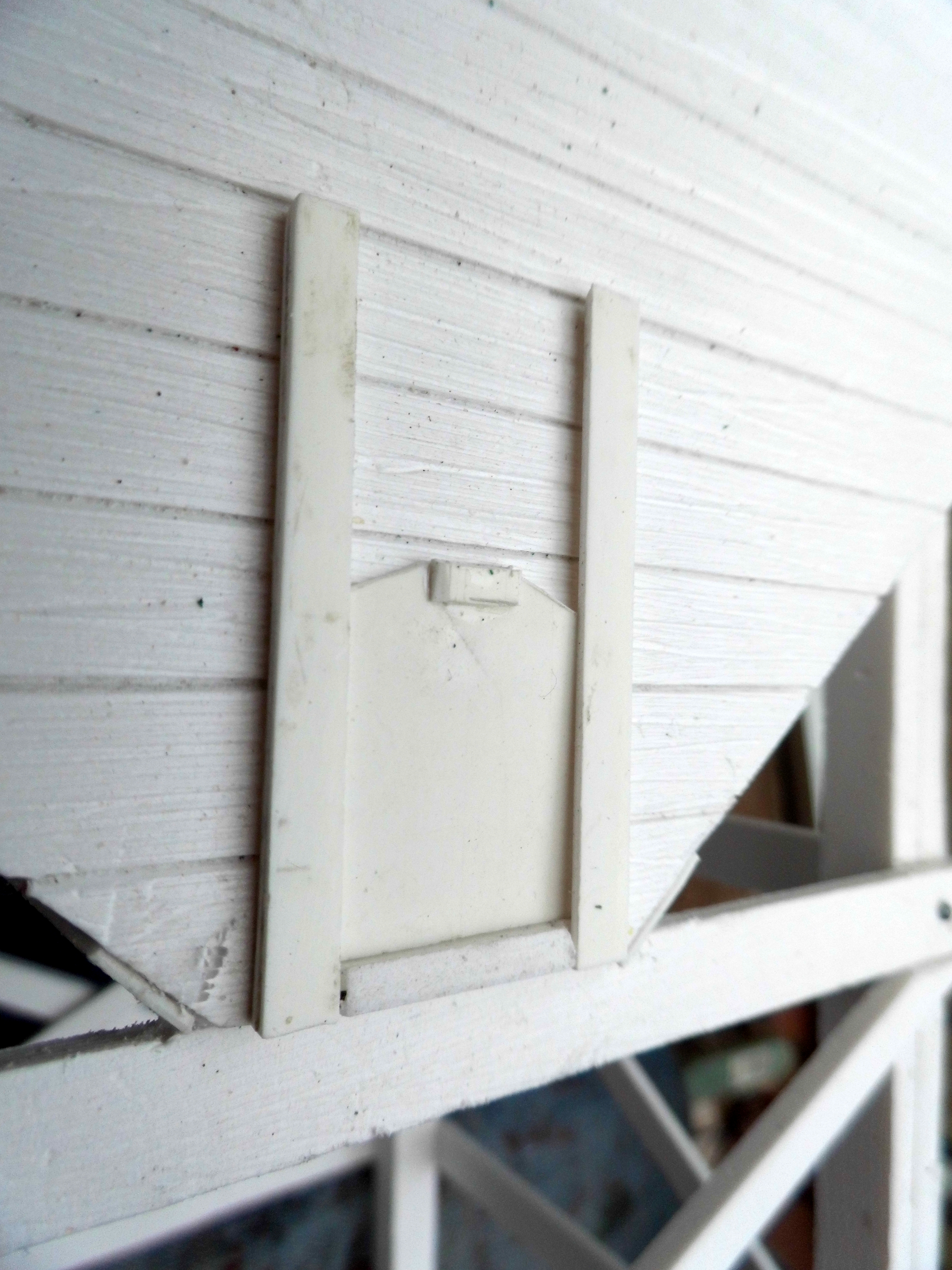
The loading chute was then tackled. A 26mm x 25mm piece of plasticard was cut for the sliding door.

Two 50mm long pieces of 1.5mm plasticard were cut for each channel for the sliding door on either side of the doorway: one piece was 3mm wide and the other 5mm wide.

 The chute was made from a piece of 40mm x 31mm 1.5mm thick plasticard, with a 40mm x 5mm strip each side.

The door was slotted into its guides and a small piece of plasticard glued on as a handle.

Hinges for the chute were made from a couple of pieces of 1.5mm thick plasticard: 5mm x 10mm

These were glued either side of the door and 1mm diameter bolts and nuts inserted to provide pivots.


15mm brass sheaves or pulley wheels were bought from Cornwall Model Boats. These were mounted on offcuts of plasticard.


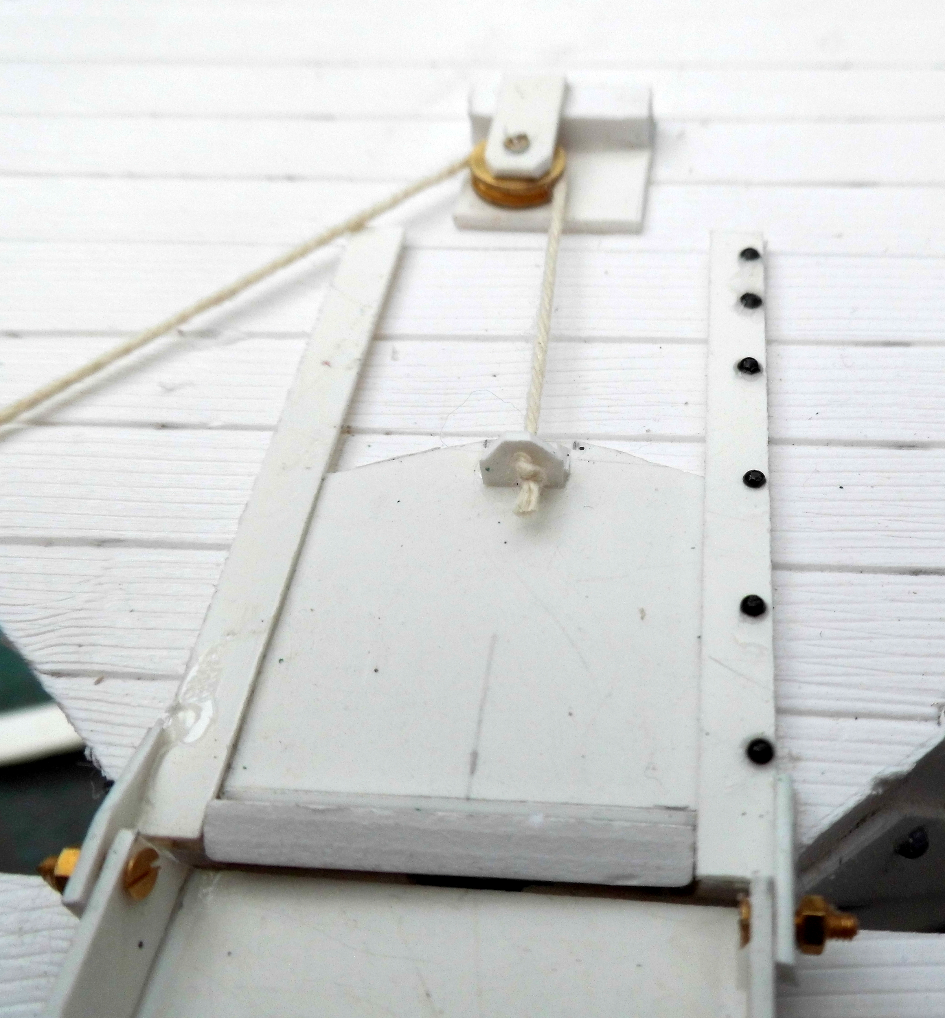
A single pulley block was mounted above the sliding door......

...... and a double pulley block on one of the front legs


 A length of linen book-binding thread was attached to the sliding door handle ........

 ..... and passed through the two pulley blocks.


A cleat was made from a few offcuts of plasticard ......

..... and glued to the leg below the double pulley block. The end of the thread was wrapped around it.

Various strengthening plates were cut from 1.5mm plasticard and glued to strategic points on the framework, ......

....... with nail art gems applied to simulate bolt heads

 Above processes were repeated until three identical loading hoppers had been made.


 The hoppers were given a couple of coats of Halford's grey primer from a rattle can aerosol.


 The planking was given a thin wash of black acrylic to highlight the grain and the divisions between the planks.


 The metalwork was picked out in black acrylic.

And then spots of rust (orange and burnt sienna) were applied.


A piece of 5mm ply was cut to fit into the hopper.

A piece of foam packaging was stapled to it, leaving one side unstapled, .....

 ...... so it could be stuffed with offcuts of foam.

Some ply spacers were put into the hopper.


The foam covered insert was then put inside and covered with PVA adhesive.

It was then sprinkled with Play Sand. I could have used Cheshire Red builders' sand but decided that a contrasting seam of silver sand had been uncovered along the foot of the Peckforton Hills.

A foil baking tray was acquired (one for each loading hopper) ......

..... and but into 120mm wide strips.

These were passed through a paper corrugator to create corrugated iron sheets.


 The sheets were painted with red oxide primer and then glued and pinned to the roof supports.


 The roofs were then weathered with acrylics.


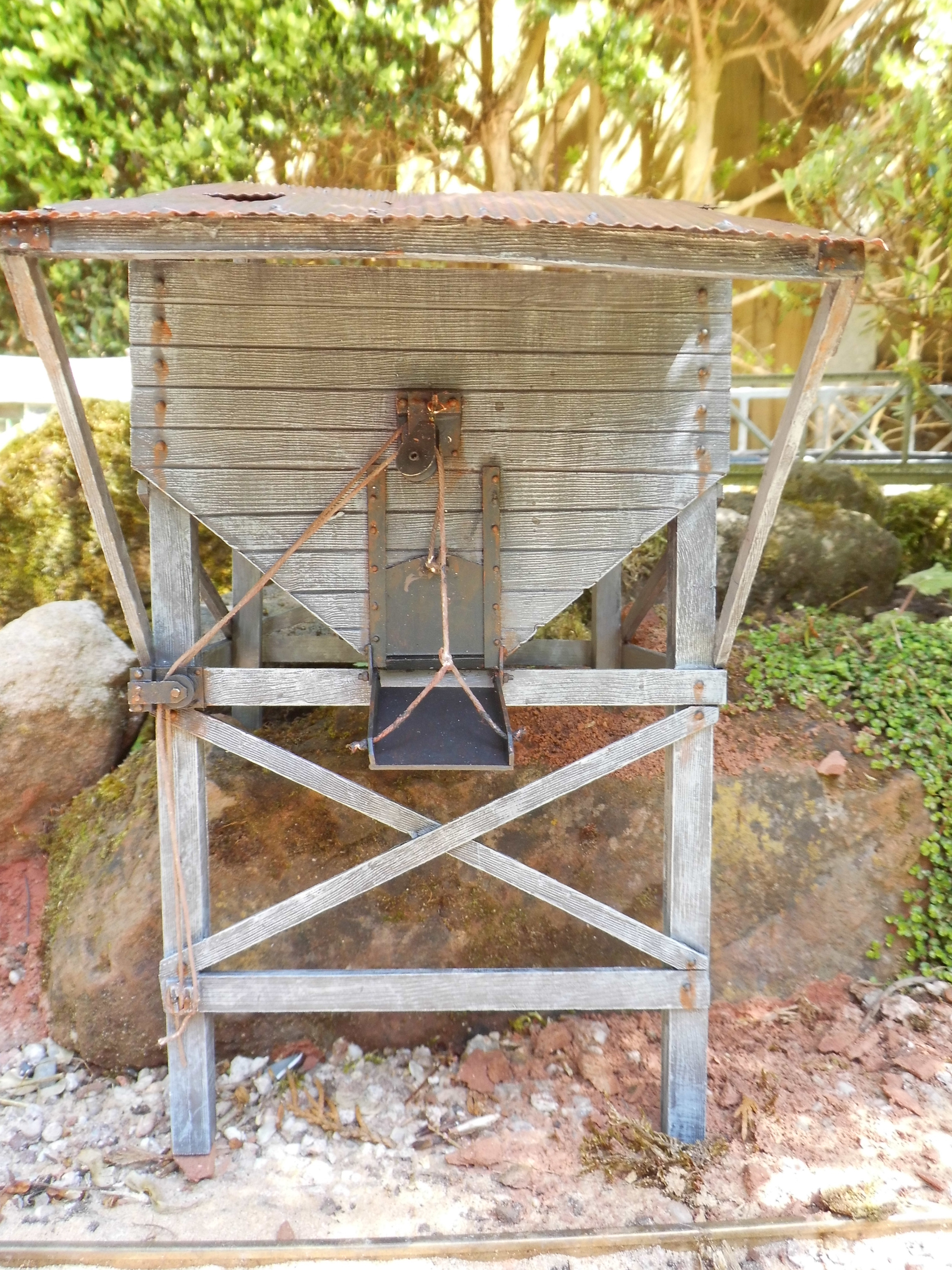
Another single pulley was attached above the sliding door pulley and a thread tied to the chute.


Various other parts of the hoppers were then subtly weathered before they were installed below the two foot gauge feeder railway running along the embankment on the quarry siding (see How I created a concrete embankment for the sand quarry).


Since completing the hoppers, the sand quarry siding has now been extended. So far, I haven't decided exactly where the hoppers will be located and how they will then be replenished.

There's always a list of jobs on the ToDo list - and this is yet another.