Showing posts with label point motors. Show all posts

Tuesday, August 17, 2021

Progress Report 92

 July has been an extremely busy month family-wise and so very little has been done on the railway. A pity, really, as there have been some good spells of weather. However, I've been told that there are times when the family must take precedence and who am I to argue?

I have managed to complete three projects - a new siding was added to Bickerton Station, scratchbuilt manual point levers and I have found a way of controlling points with servos using cheap servo testers. Apart from those projects, the railway and workshop have lain dormant for a few weeks.


Permanent Way

New siding at Bickerton

Over the years, I have been steadily constructing, adapting and acquiring goods rolling stock because I really enjoy the operational aspects of running my railway. I have developed several computer based freight management systems to make the handling of goods traffic more interesting (see Computerised freight management and Managing freight with my Psion pocket computer).

There are five stations on the Peckforton Light Railway, each with sidings, and three additional lineside industries served by their own branchline or sidings. Over the years I have steadily expanded the number of sidings at each of my stations, apart from one - Bickerton where, until now, I have always thought there was insufficient space for expansion.

I created room for another siding simply by adding a plank to the front of the station which is mounted on a couple of paving slabs.


 I took the opportunity to improve the appearance of the rear of the platform - using PVC foamboard and 3D printed fencing.

Owing to a combination of family ties and poor weather, I've not yet had a chance to run trains since this modification was completed, but I'm hoping the weather will improve before August is over.

For more information see - How I added a new siding to Bickerton Station


Scratchbuilt point levers

Although LGB point levers are spring-loaded and are fairly robust (the can withstand being stepped on) they are not particularly realistic when compared with the weighted point levers found on most UK based narrow gauge railways. I therefore decided to construct my own. After a few experiments, I have perfected the design which makes use of a couple of sleepers from a plastic sleeper strip, a few bits of brass, some brass disks and some brass M2 screws.

They allow stock to trail through the point against the route set but, unlike LGB point levers, the blades don't swing back. It might be possible to achieve this by altering the distance between the pivot and the linkage on the lever, but I've not yet found a reliable means of achieving this and so, for now, I'm happy for the blades to be switched by the flanges on the wheels.

For more information see - How I construct point levers


Controlling points with servos and servo testers

The majority of points on the railway are operated manually with a mixture of LGB and scratchbuilt point levers (see below). However, some of the more inaccessible points are operated remotely using LGB point motors and a modified Deltang radio control system (see How I operate some of my points using Deltang equipment)

I have two sets of storage sidings at opposite ends of the railway (see How I made storage roads in the garage). Until now, I have resisted operating the points in the storage sidings remotely - after all, they are only ever used at the start and end of operating sessions. However, I got fed-up with trotting in and out of the garage and lean-to to change the points and so looked for ways of operating these points by remote control. The points in the lean-to are now operated using simple point rodding (see Operating points with simple point rodding) but this wasn't feasible for the points in the garage as space was much tighter and so I found a way of modifying cheap servo testers to operate them with servos.


The two points in the garage are now operated by servos ........

...... controlled by a couple of toggle switches mounted in a box which hangs from a hook beside the access flap to the sidings (the other switch is the on-off switch).

For more information, see How I operate points remotely using servos and servo testers


As I look out of the window while writing this update, the rain is starting once more. After the heatwave in June, the weather is now unseasonably cool and the weather each day is very unpredictable - certainly not conducive to running trains.

At least it's providing me with an opportunity to catch up with a few jobs in the workshop - see next month's progress report.....


<<< Previous Progress Report              Next Progress Report >>>


Tuesday, June 10, 2014

Progress Report 52

The weather has been very mixed since the previous update (See Progress Report 51). There have been a few days of sunshine but mostly the weather has been showery, which is the worst type of weather for playing trains - no sooner have I put out equipment than I have to gather it up, trying to decide if it will be a short sharp shower or a more prolonged downpour. Fortunately, with radio control and battery power, I have been able to run the odd train now and again. However, I have managed to get one full running session in, and the wet weather has given an opportunity for several indoor projects to get completed.


A Day in the Life of Peckforton Station

During the full operating session, I set up my video camera at Peckforton Station and, each time a train passed through, filmed its progress. The result is a video showing a typical day in the life of one station on the line. The video has condensed the day into a series of brief episodes, but the feedback from fellow modellers has been encouraging.

In addition, I took a series of stills from the video sequences, and produced a blog posting outlining the day's activities. (See A Day in the Life of Peckforton Station)

Track sweeper

Although track cleaning is no longer the pain in the butt which it used to be, locos and stock can still be derailed by the dreaded 'leaves on the line' and other debris.  I've discovered, for example, that from time to time, blackbirds and thrushes like to use the rails as anvils to crack open snail shells. Whilst, I still have to cut back the vegetation (on a weekly basis at the moment), it's still necessary to check the track before each running session - even one twig can have disastrous consequences. To help this tidying-up process, I have produced a simple track sweeper which can be sent around the track before a running session to remove the general detritus which the track seems to accumulate. (See How I constructed a track sweeper)

Take one HLW wagon chassis, a couple of pieces of brass rail, some brass strip, a motor, battery and a bottle brush and voila!


Trestle Bridge

In the previous Progress Report (see Progress Report 51), I gave an account of the building of the mill siding. The track crossing the stream had been left hanging in mid-air, awaiting the construction of a suitable bridge.This has now been completed (see How I constructed a small wooden trestle bridge), based (loosely) on the wooden trestle bridge which was situated on the Southwold Railway beside the water mill between Halesworth and Wenhaston.

At the moment, the bridge looks very new, but now it has taken up permanent residence, it will weather naturally.

Flat wagons

Adding details to the match truck

Following suggestions from fellow modellers on the G Scale Central forum, I've added a few more details to the match truck which will accompany the mobile crane whenever it ventures forth.

The detailing includes a couple of baulks of timber, a coil of rope, some chain and various other utilitarian objects such as a tool kit and re-railing jacks. I may distress and weather the wagon still further as it would be likely to suffer considerable abuse as it goes about its duties on the railway.

A new permanent way wagon

I decided that, rather than making the above wagon a general purpose Engineering Department wagon, I would make another flat wagon more specific to platelaying to be towed behind the IP Engineering Lollypop Railcar (see How I constructed an IP Engineering railcar) which I have designated as an platelayers' trolley.

The flat wagon uses an IP Engineering Hudson wagon chassis as its basis, with a coffee-stirrer body and tools provided by Bachmann. It needed to be small in size to match the dimensions of the railcar, and looks appropriate as it trundles around the railway (see How I constructed a small flat wagon).

Points controller

Having decided to move over from DCC controlled track-power to radio controlled battery power, one of the sacrifices was going to be the remote control of some of my pointwork from the DCC remote handset. Casting around for alternatives, I discovered the Deltang points and accessories controller which has seven outputs. As I had six turnouts which needed to be controlled remotely (owing to their awkward locations), this seemed to be the most appropriate solution. However, the controller is designed to work with r/c servos rather than LGB point motors and so I was faced with the dilemma of either replacing all the existing LGB point motors with servos, or finding some way of adapting the Deltang controller so it would operate the LGB point motors.

 Following the guidance of a fellow garden railway modeller (who, incidentally is based in Australia), I programmed a Picaxe microprocessor to respond to the Deltang receiver and generate a half second pulse of electricity to kick the relevant LGB points motor into operation.

It was surprisingly easy (and equally surprisingly inexpensive), to construct a system which would operate relays in response to the instructions generated by the microprocessor. I can now control my more inaccessible pointwork by the flick of a switch.

Wiring-up the most distant turnout

The most distant point (on the approach to the swing bridge) had not been hard-wired - it used a slot-in decoder connected directly to the track. This needed to be connected to the points controller, situated in the outhouse about 40m away. I happened to notice a couple of lengths of orange mains cable which my neighbours had thrown away in a skip which they no longer needed. This was pressed into service, routed around the outside of the garden and then buried.

Station Buildings

Until now, I have left my station buildings outside throughout the year and, even though they are constructed from resin castings or plastic (see How I constructed some station buildings and How I constructed a station building from a toy, they were beginning to show signs of wear and tear. Some of the epoxied joints had sprung apart and the paintwork was beginning to peel in places see Progress Report 50).

The buildings were brought inside and all the internal joints (regardless of whether they had failed) were reinforced with a strong instant-grab, flexible adhesive.

The representations of timber framing were repainted green and some of the roofs were touched-up but I decided to leave the cream clapperboard as it was as this was generally surviving well (it was watered-down masonry paint designed for outdoor use with a ten year guarantee). The posters and signs were all reprinted and re-applied (see How I made some period posters and enamel signs). Some posters were mounted on noticeboards, made from black plasticard (see How I made some noticeboards)


I have decided to bring my buildings inside during the winter months from now on to prolong their working lives (and to save myself unnecessary maintenance).
The station buildings and platform paraphernalia ready to be installed in the garden
Peckforton Station building in situ
Beeston Market Station building


Platform detailing

Whilst re-installing the buildings, I decided to assemble and paint various kits and general clutter of platform equipment which I had accumulated, such as trolleys, firebuckets, seating, luggage, etc.

These items had come from various sources including Trenarren Models, Garden Railway Specialists, Roundhouse, Modeltown and Back2Bay6.

These items were constructed and then given a couple of coats of primer, before being given a final coat of green or red, with detailing added with acrylics.

As time progresses, I will add more and more items of this sort as it seems to me that this type of detailing is what brings a railway to life.

Monday, May 01, 2006

How did I do the electrics?

Sections
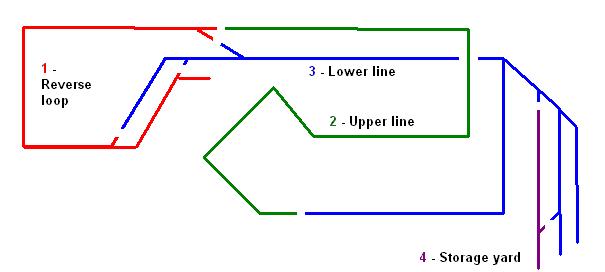
I have tried to keep the wiring as simple as possible, having only four sections:


  • The reverse loop and through station
  • The upper line from the crossover to the patio bridge
  • The lower line from the crossover to the patio bridge - also includes the terminus station
  • The storage yard
I will probably operate a simple service - no more than one or two locos 'in steam', hence having the option of being able to isolate one train while running another.
I thought long and hard about the reverse loop but decided it would be worth including it in the plan. I will thus be able to operate the layout as:
  • continuous loop
  • out-and-back (via the reverse loop)
  • and end-to end - using the through station as a terminus
The reverse loop will have a separate DPDT reverse switch to enable a train to run across the cross-over without causing a short circuit. However, this 'reversed' train will have to stop at the through station to have the polarity un-reversed.
I did contemplate using a diode bridge in the loop but as I will want trains to run in both directions around the loop had to reject it. For those who are unfamiliar with the diode bridge - four diodes are linked together:

This means that regardless of the polarity of the input from the controller, the output will remain unchanged. Thus, once the train is on the loop, the controller can be reversed and the train will continue in the same direction. If the controller is reversed quickly or via a reversing switch, the train will not appear to stop - though may hesitate slightly. As indicated above, because the polarity of the supply to the loop is fixed, dertermined by the diodes, trains can only travel in one direction around the loop.
Wiring
I have used domestic 1.5mm T/E (twin and earth) cable for the wiring. Once it situ, the cable will not be moved a great deal and hence does not need to be flexible. I also wanted something that would not lose to much voltage over the long runs in the garden. T/E cable has a single solid copper core rather than being multistranded; I felt solid cable would be less likely to deteriorate than multistrand over time.
Pointwork
I have opted for electrically operated points throughout. Initially, this decision was made for me as the LGB R3 points are only available as electrically operated versions. However, I decided that the extra wiring involved would ultimately be worthwhile as it will mean all points will be able to be operated centrally.

Where possible points are electrically linked. Hence, the two cross-over points are wired together so they will change simultaneously. This not only helps to prevent accidents, it saves on wiring - only one cable needs to be run from the control panel to the crossover.
Bonding
All rail-joints are bonded with soldered jumper leads.

A few years ago I invested in a 75 watt soldering iron and am very grateful for this decision. Once the iron has reached its operating temperature it is very easy to heat the rail to the right temperature. I intend to varnish all the soldered joints to prevent oxidisation.
From experience, I have two pieces of advice:
  • 1. Remember where you place the iron and try not to rest your hand on it!
  • 2. Make sure you pick up the iron by the handle !
I can testify (and show the scars) as to what happens if you ignore this guidance!
Control panel
The control panel has yet to be constructed - at present all wires end in an interesting cat's cradle in the lean-to. The intention is to create a switch-box which will control the four sections and the pointwork.