This Blog describes the ongoing development of a 16mm scale 45mm gauge garden railway situated in the North West of England, UK from 2004 to the present day.
Recently, I needed to reprogram a Micron MR603 receiver so it could be used to trigger all the sound effects on a Micron Mini Sound module (MSND01). As this module uses the same firmware as MyLocoSoundmodules, this reprogramming would also be appropriate for these.
The sound module has seven functions triggered by inputs on seven pads (or screw terminals):
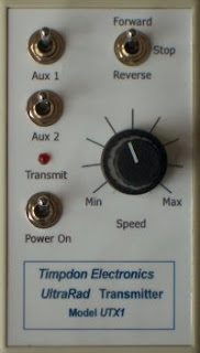
.... which has two two-way switches and two push-buttons for triggering outputs from the receiver, ....
S1 A - sends Channel 3 high
S1 B - sends Channel 3 low
S2 - sends Channel 4 low
S3 C - sends Channel 7 high
S4 D - sends Channel 7 low
Bind button - sends Channel 5 low
.... thus allowing all six of the additional sounds on the Micron or MyLocoSound modules to be triggered.
The Micron MR603 has ten output pads which, as delivered, provide the following outputs:
P1 - Front light / LED2
P2 - Rear light
P3 - 0v - 3.3v when Channel 3 is low
P4 - 0v - 3.3v when Channel 3 is high
P5 - 0v - 3.3v when Channel 5 is low
P6 - 3.3v - 0v when Channel 5 is low
A - Front light
B - Rear light
C - 0v - 3.3v when Channel 5 is low
D - 0v - Toggle 3.3v/0v when Channel 5 is low
The Micron Mini sound card inputs (and the MyLocoSound inputs) are trigged when they are connected to 0v and so, to make use of all the features, I needed to change some of the outputs from the pads to give 0v when the channels used by the buttons and switches on the Tx22X went high or low.
So, I decided to reprogram the receiver's output pads as follows:
P1 - Unchanged (i.e. Front light)
P2 - Unchanged (i.e. Rear light - not used)
P3 - 0v when Channel 3 is low (i.e. when S1 A is clicked on the Tx)
P4 - 0v when Channel 3 is high (i.e. when S1 B is clicked on the Tx)
P5 - 0v when Channel 4 is low (i.e. when S2 on the Tx is pressed)
P6 - Unchanged (i.e. 0v when Channel 5 is low (i.e. the bind button is pressed on the Tx))
A - Unchanged (i.e. Front light - not used)
B - Unchanged (i.e. Rear light - not used)
C - 0v when Channel 7 is low (i.e. when S3 C is clicked on the Tx)
D - 0v when Channel 7 is high (i.e. when S3 D is clicked on the Tx)
This is probably the part of the process which most people find confusing, so I will try to describe how it works as clearly as I can.
Let's take the changes needed for P3 as an example. The pad needs to be reprogrammed so that it provides a 0v output when the receiver detects that Channel 3 has gone low.
So, working our way across the section of the table shown above:
The first value we need to note down is 3 which tells the receiver we want to reprogram an on/off feature
Moving to the next column, we need to tell the receiver we want to reprogram pad 3. So 3 is our next value to be noted.
Moving to the third column, we want the output from the pad to be momentary - i.e. we only want the output to happen while the button or switch on the transmitters is being pressed or clicked. As soon as the button is released the output from the pad will revert to whatever it was doing when the receiver was switched on. So, our next value is 1.
The fourth column, specifies the Channel we will be using. In this case it is Channel 3 and so 3 is the next value to be noted.
The final column specifies what sort of output we want dependent on the state of the selected Channel. We want the output to start high (on) but switch to low (off) when the Channel goes low. So, we want this value to be 4 (i.e. When Channel 3 goes low, turn off the pad (i.e. it has 0v output))
So, the reprogramming code we need for this change is - 3, 3, 1, 3, 4
Let's skip to the last output in our list, Pad D. This needs to provide a 0v output when Channel 7 goes high.
Again, our first value is 3, indicating we want to reprogram an on/off setting
This time we want to reprogram Pad D - so we note down our next value as 10
Again, we want the output to be momentary, and so our third value is 1
We are using Channel 7, so our next value will be 7
And finally, as we want a 0v output when Channel 7 goes high, the value we need is 6
The coding for this change is therefore: 3, 10, 1, 7, 6
So, on this basis, the codes needed for each of the pads which need to be reprogrammed are:
P3 - 3, 3, 1, 3, 4 (for 0v when Channel 3 is low)
P4 - 3, 4, 1, 3, 6 (for 0v when Channel 3 is high)
P5 - 3, 5, 1, 4, 4 (for 0v when Channel 4 is low)
C - 3, 9, 1, 7, 4 (for 0v when Channel 7 is low)
D - 3, 10, 1, 7, 6 (for 0v when Channel 7 is high)
Putting the receiver into programming mode
To actually make these changes, we firstly need to make sure the MR603 receiver has been bound to a transmitter which has a reversing switch (i.e. which can give a high and low output on Channel 3). In the Micron range, this would include:
To put the receiver into reprogramming mode, the transmitter and receiver must be switched on. After a few seconds, the morse code for SOS (dot, dot, dot, dash, dash, dash, dot, dot, dot) has to be tapped out on the bind button. The dots must be less than a second in duration and the dashes more than a second but less than five seconds. The pauses between dots and dashes must be less than 5 seconds.
When the receiver has entered programming mode, its LED will flash once every second (referred to as 1-flash)
Reprogramming
We can now start the reprogramming process.
Taking our first set of values needed to reprogram Pad 3 (i.e. 3, 3, 1, 3, 4), we need to change that initial 1-flash to a 3-flash (i.e. three one second flashes, followed by a pause). To increment the number of flashes, the reversing switch on the transmitter need to be moved to the "reverse" or "down" position and then returned to the mid-position. Clicking it once will increase the flash-count by one. Clicking it again will increase the flash-count by another one. Thus, the LED should now be flashing three times before a pause. This is the value we need for the first code in our list (i.e. telling the receiver that we want to reprogram an on/off setting). To tell the receiver to "accept" that value, we move the reversing switch to "forward" or "up".
The LED will now start flashing once per second. We need to it flash three times, so we increment the number of flashes twice (by clicking the reverse switch twice in the "reverse" or "down" direction). Once it has reached 3-flash (three flashes then pausing), we "accept" this by clicking the reverse switch "forward" or "up". This tells the receiver we want to reprogram Pad 3.
LED should now flash 1-flash again (because Pad 3 is already set for momentary on/off). So we just click the reverse switch forward or up to accept this value.
The LED should now start flashing 3-flash, as P3 is already set to respond to Channel 3. So click the reverse switch to forward or up to accept this.
Finally, the LED should now start flashing 1-flash as the default for P3 is to give a 3.3v output (i.e. go high) when Channel 3 goes low. We need to change this to start high and go low when Ch3 goes low, so we need to change this value to 4-flash by incrementing the flashes by three reverse or down clicks and then accepting the 4-flash by clicking forward or up.
If you accidentally increment the number of flashes by too many, then keep incrementing until the LED reverts to 1-flash, then increment to the desired value.
After entering the final value in our list, the LED should stop flashing and revert to solidly on.
To program another pad, we need to re-enter programming mode with the SOS morse code sequence on the bind button.
All that might sound a bit daunting but, once you've done it a couple of times, it is really easy - albeit slightly tedious.
Here's proof that all that effort is worthwhile.
Deltang or RC Trains transmitters
Deltang or RC Trains receivers with reversing switches can also be used to reprogram Micron receivers provided they will bind with the receiver. Some of the very early Deltang receivers are unable to bind with Micron receivers and will need their transmitter boards replacing to enable them to do so. This is a job which can be done by Andy at Micronor by Phil at RC Trains. Alternative, if you are handy with a soldering-iron, it is a relatively straightforward job you can do yourself, once you have purchased the Micron transmitter module.
I have organised this post to, hopefully, cover various combinations of soundcards and Deltang / RC Trains receivers. I cannot cover all possible combinations but have focused on the soundcards and receivers which I have used on my own railway, ie:
Hopefully there will be something here which meets your needs - if not directly then maybe the information could enable you to apply the general principles shown here to other soundcard/receiver combinations.
How soundcard effects are triggered
The majority of soundcards require 0v inputs to trigger their special effects (apart from DCC interfaced soundcards). In essence, to trigger an effect (such as the whistle), the input terminal on the card needs to be connected to the negative (0v) terminal of its power supply. This could be done with a simple switch such as a push button, or a reed switch mounted under the loco and operated by a magnet placed on the track.
However, with radio control, it is possible to trigger the effects remotely at any time by pressing a button or flicking a joystick on the transmitter. The receiver in the loco interprets this signal and in some way connects the 0v (negative) supply to the relevant input on the soundcard.
For example, a servo connected to the receiver could be arranged to press a push-button switch. My friend in Australia (Greg Hunter - Sandstone and Termite Railway) uses servos to operate reversing switches in his locos .......
and servo operated push-button micro-switches for controlling accessories.
Alternatively, it is possible to buy switching units which can be connected to the pins of the receiver to carry out the switching.
By contrast, the great advantage of theDeltang / RC Trainsreceivers is that they have outputs which can deliver 0v without the need for any external circuitry.
Below are some examples of how various soundcards can be connected to Deltang receivers to trigger onboard effects such as a whistle.
The Deltang / RC Trains Rx65b receiver
The Deltang / RC Trains Rx65b receiver/controller has fifteen pads which provide outputs and can be used as inputs (eg for sensing when a reed switch has been activated by running over a magnet).
Pads 1- 12 provide outputs of 3.5v or 0v (ground) and are limited to a maximum of 20mA output (but lower is better!). Pads A, B and C are buffered and provide either 0v (ground) when on or are 'floating' (ie disconnected) when off. They can handle currents of up to 2 amps (but lower is better - remember the whole Rx is rated at 2A including the motor!).
The outputs respond to signals sent from various transmitter channels. The way each pad responds to signals can be reprogrammed (see How to reprogram Deltang receivers) but they are provided with a useful set of default values when they are initially purchased.
Since the Rx65b was released in 2014, the default outputs have changed. From November 2015 (version 611-11 - shown by two 11s in gold on the large chip on the circuit board), .........
This is an Rx65b v611-10
This is an Rx65b v611-11
.......... the default outputs on the Rx65b v611-11 suitable for controlling soundcards are:
Item
Setting
Details
P3
On/Off
Ch2, Idle high, 0v when channel is Low, Momentary action
P4
On/Off
Ch4, Idle high, 0v when channel is Low, Momentary action
P5
On/Off
Ch5, Start high, toggle when channel is Low, Latching action
P9
On/Off
Ch3, Idle high, 0v when channel is High, Momentary action
P10
On/Off
Ch3, Idle high, 0v when channel is Low, Momentary action
P11
On/Off
Ch3, Start high, toggle when channel is High, Latching action
P12
On/Off
Ch3, Start high, toggle when channel is Low, Latching action
P15 (C)
On/Off
Ch5, Start disconnected, 0v (on) when channel is Low, Momentary action
To some readers, the above table may look like gobbledegook initially, but with a little explanation, hopefully it will make more sense.
For example, the output from P3 (Pad 3) is normally high (ie gives 3.5v) but when the receiver gets a signal from the transmitter on channel 2, the output changes to 0v until it no longer receives that signal - ie it will deliver 0v while the button is being pressed on the transmitter.
The output from Pad 5 starts off high (3.5v) but changes to 0v when it receives a signal on Channel 5 (eg when the bind button is pressed on Deltang transmitters). It will stay at 0v until Channel 5 (the bind button) is activated again.
Because soundcards tend to operate with an internal voltage of 5v and Deltang receivers have an internal voltage of 3.3v or 3.5v, it is advisable to put a 1k ohm resistor in the leads connecting the output pads of the receiver to the input pads of the soundcard to help prevent excess current being passed from the soundcard to the receiver (see below).
Connecting the Rx65 to a MyLocoSound (MLS) Universal steam soundcard
The most recent version of the Universal MyLocoSound (MLS) soundcardhas five input triggers for:
Loco whistle
Bell
Guard's whistle
Safety valve
Airbrake pump
in addition to its digitally created steam or diesel engine sounds which can be either synchronised with the motor voltage or a wheel cam.
Any of the pads which deliver 0v can be used to trigger the MLS card. This is how I have wired-up a MyLocoSound sound card to one of my locos which is bound to a Deltang / RC Trains Tx20 transmitter:
Pad C (Channel 5 / Bind button) to soundcard F1 input (Whistle)
Pad 3 (Channel 2 / Function button on Tx20) to soundcard F2 input (Bell)
Pad 9 (Channel 3 / Direction switch fwd) to soundcard F3 input (Guard's whistle)
Pad 4 (Channel 4 / Function button on Tx20 or reprogrammed Inertia knob on Tx22 or Tx24) to soundcard F4 input (Safety valve)
Pad 10 (Channel 3 / Direction switch rev) to soundcard F5 input (Airbrake pump)
Here's a video of the set-up in action with my RC Trains Tx20transmitter which has buttons to energise Channels 2, 3 (direction switch), 4 and 5 (bind button).
Connecting the Rx65 to the MTroniks / Spoerer DigiSounds card
As the name suggests, the MTroniks / Peter Spoerer DigiSoundscard uses digitised sounds to emulate the sounds of a diesel loco. The one I use in my locos is the Small Diesel card. Originally intended for boats, it comes in a waterproof housing with standard JST spaced pins for connection. It has two inputs - one to trigger the horn and the other to trigger the engine start/stop effect so the wiring for this is much simpler.
As with the MLScard above, any of the pads which deliver 0v can be used to trigger the sounds but in my IP Engineering 'Jessie' loco, I use the bind button on my Tx22 to trigger the horn and the direction switch for starting and stopping the engine sound. I have therefore used Pad C to trigger the horn and Pad 12 to trigger the engine start/stopeffect.
A short video of the soundcard in action (Please note - in this video I had reprogrammed an Rx65b v611-10 to provide non latching 0v outputs on P12. On the Rx65b v611-11, a latching 0v output is provided by default on P12 and so there is no need to leave the direction switch in the 'on' position. Flicking it 'on' and then off will start the engine sound and then flicking it 'on' and off again will stop the engine sound - I must make another video!)
Connecting an Rx65b to a Dallee DC v3 soundcard
I have two Dallee sound cards installed in my locos, one for steam sounds and the other for a diesel railcar. The wiring is the same for both. This is the Dallee DC v3 steam card. This card has now been superseded by a more recent model but the wiring will be largely similar.
As with all the soundcards shown here, the Dallee DCv3 card needs to
be wired up to the battery supply and to the motor leads initially. Once
that has been achieved, then various triggers can be connected to the
0v outputs of the Deltang / RC Trains Rx65b receiver.
In my case, I connected the whistle trigger input to Pad C, the cylinder blow-down (or full revs) trigger to Pad 11 and the sounds off trigger to Pad 12.
On a Deltang / RC Trains Tx22 transmitter, this means the whistle sounds when I press the Bind Button (Channel 5 low), the cylinder blow-down sounds when I flick the Direction Switch to the forward position (Channel 3 Low) and the sounds are muted when I flick the Direction Switch to the reverse position (Channel 3 High).
Here's the soundcard in action in my 'Anglicised' LGB Stainz locomotive. Still some slight adjustment needed to sync the chuffs to the motor voltage but it does demonstrate the various sounds in operation.
Connecting an Rx65b to a Phoenix 2k2 soundcard
I was fortunate enough to pick up a secondhandPhoenix 2k2 sound card on eBay for a very reasonable price. It was fitted to a flat wagon with wheel contacts, presumably so it could be towed behind any track powered loco to provide 'portable' sound effects.
When I bought the card, it was programmed with USA diesel sound effects
which, of course, were quite inappropriate for my UK based narrow gauge
railway and so I sent it off to Phil Partridge who now owns and runs RC Trains. He has the equipment and the wherewithal to reprogram Phoenix sound cards and so he set it up for me with a European steam sound. The whistle sounds quite meaty but I am impressed by the range of additional sounds which this card provides.
It was wired-up to an Rx65b in the usual way but as there are several sound triggers, I set it up so it would work with a Deltang/RC Trains Tx20 transmitter, which has a couple of additional buttons which use Channel 2 and Channel 4.
As can be seen, Pad 3 (Channel 2) is connected to trigger input 13 (bell), Pad 4 (Channel 4) is connected to trigger input 10 (drifting), Pad 9 (Channel 3 High) is connected to trigger input 12 (coal loading) and Pad 10 (Channel 3 Low) is connected to trigger input 11 (water fill) and Pad C (Channel 5) is connected to trigger input 14 (whistle).
This means that when I press the F1 button on my Tx20 transmitter, the bell sounds; when I press the F2 button, the loco chuffs start drifting rather than labouring; when I press the bind button, the whistle sounds; when I flick the direction switch forwards the coal fill sound starts when the loco is stationary and which I flick the direction switch the other way, there is the sound of the loco's water tank being filled.
Here's a video of the loco in action demonstrating all its sounds ......
The Deltang Rx102 receiver
The Deltang Rx102 is a fairly standard DSM2 receiver which does not has an ESC incorporated on the same board in the same way as the Rx65b. It can be connected directly to servos to operate, for example, the regulator and reverser controls on a live steam locomotive, or can be connected to a third party ESC such as the Brian Jones Mac 5 or the MTroniks Viper Loco 10.
The default outputs from the pins of the Rx102 are for directional lighting (Pins 6 and 7) or servos (Pins 1-5 and 8).
Pins
Default setting
Pin1:
Ch1 Servo [Throttle]
Pin2:
Ch4 Servo
Pin3:
Ch3 Servo [Direction]
Pin4:
Ch2 Servo
Pin5:
Ch5 Servo
Pin6:
Front light
Pin7:
Rear light
Pin8 (side):
Ch6 Servo
However, to make the Rx102 more suitable for triggering sound card effects, it is possible to reprogram the pins to give 'on/off' (ie 3.1v / 0v) outputs. Unfortunately this cannot be done with a Deltang or RC Trains Tx20 transmitter which is by far the easiest way; the reprogramming has to be done with a Deltang Prog 3 or Deltang Prog 4 programmer module which can be tricky to set-up (for more information see How to reprogram Deltang receivers).
Connecting the Rx65b and an Rx102 to a Technobots Programmable soundcard
The Technobots programmable soundcardwas originally developed for use in model boats but is well suited to the production of sounds for small to medium sized narrow gauge diesel locos.
As suggested by its name, the twelve electronically generated default
engine sounds can be reprogrammed to create your own tailored versions.
It has two inputs, for engine speed and horn. Unlike other soundcards
which detect the motor voltage from the ESC, the engine speed is
determined by the servo signal from the receiver. As the Rx65b
integrates the receiver and ESC on one board, the connection between the
receiver and the ESC is internal to the board and not normally
accessible. However, Pad 8 mirrors the servo output from Channel 1 and,
theoretically, it should be possible to connect the Technobots
Progammable Soundcardto an Rx65b using Pad 8 for the engine speed input and, say, Pad C for triggering the horn with the bind buttonor Pad 12 to trigger the horn from the Direction Switchon the transmitter.
However, I experienced difficulties with this arrangement in my diesel loco. The engine sounds worked well when going forward but were erratic when in reverse. Alan Bond, who developed the Technobots card, found no difficulty in interfacing his soundcard with an Rx65b in this way and so I have included the wiring diagram here in case you have more success. I experimented with other ways to interface this soundcard - so these are shown below.
This approach is probably the most straightforward. A third party ESC (I used a Brian Jones Mac 3) is connected to an RCT/Deltang Rx102. The 'servo' signal from the receiver passes to both the ESC and the soundcard. Pin 5 of the Rx102 was reprogrammed with a Deltang Prog 3 programmer so that it was 'off' (ie 0v) when the bind button (Channel 5) was pressed on the transmitter (see How to reprogram Deltang receivers). This worked well but I was finding that the level of motor control I was getting from the ESC was not as precise as it is from an RC Trains/Deltang Rx65b, particularly at slow speeds. As you may know from various videos of the Peckforton Light Railway (eg , operation and control are very important to me.
Eventually I decided to use a hybrid circuit. An Rx65b and an Rx102are both bound to the same Selecta channel on my Tx22 - the Rx65bcontrols the motor while the servo signal from the Rx102 controls the soundcard. A 5v voltage regulator circuit provides power from the 12v supply for the Rx102. Not the most elegant solution, but it works!
Here is the arrangement in action. I used one of the twelve default sounds for this video but subsequently I have tinkered with the sounds in the programmable soundcard to devise an even more rattly, clanking diesel.
Interfacing an Rx65b with the sound module from a greetings card
After building and fitting radio control to the diminutive Plate Frame Simplex kit fromIP Engineering (see How I constructed a Plate Frame Simplex), I decided to rise to the challenge of fitting it with sound. The main difficulty was, of course, size. I couldn't find a commercially available railway soundcard which was small enough to fit inside. However, I noticed on eBay that the sound modules which are fitted into greetings cards (eg those which play 'Happy Birthday" when they are opened were available quite cheaply - in my case, £1.29 including postage.
In addition to the soundboard, there was a speaker, two push buttons (one to play the sounds and one to record) and a microphone. After recording a suitable diesel engine sound, I removed the batteries, speaker, mike and the record push button and soldered a wire from the mike input to the 'play' button input to make the sound repeat (for more information on the modifications to the module see - How I modified a greetings card module as a soundcard).
Rather than triggering the sound from the Rx65b which could have been done quite easily by connecting any of the pads which give a 0v momentary output to the play button input, I fixed the play button into the roof of the cab on the Simplex. The sound is not exactly high fidelity, but does give the impression of the Simplex motor.
I have not (as yet) found a way of overcoming a half-second pause every 60 seconds as the sound loops back to the start - but for £1.29, I'm not complaining.
As there was still sufficient space, I decided to add a second module with a recording of a klaxon horn. This was wired up to Pad C (Channel 5) of the Rx65b so the horn sounds when the bind button is pressed on the transmitter.
The engine sound diminishes when the horn is sounded which I could improve by adding a couple of resistors to the speaker output leads, but this would reduce the sound of the engine which is already quite soft and so it is another compromise with which I can live, given then overall cost of this sound system.
The Rx61b controller receiver
My Ford(ish) railmotor, bashed from two freelance Andel coaches, was constructed in 2012 and converted to Deltang radio control in 2013. This was before the Rx65 had been developed and so I equipped it with the most up-to-date and sophisticated receiver which Deltang produced at the time, the Rx61b. This had eight output pads in addition to the motor control pads.
Prior to my experiments with soundcards and Deltang's subsequent changes to the way output pads were configured by default, none of the pads provided a 0v output in response to transmitter signals. Those relevant to providing triggers for soundcards were P4 - P7.
Item
Setting
Details
P4
On/Off
Direction switch (Ch3)
Item being switched needs current limiting resistor
Switch right for ON (centre/left OFF)
P5
On/Off
Direction switch (Ch3)
Item being switched needs current limiting resistor
Switch left for ON (centre/right OFF)
P6
On/Off
Bind button (Ch5)
Item being switched needs current limiting resistor
ON while button pressed, OFF when released (momentary)
P7
On/Off
Bind button (Ch5)
Item being switched needs current limiting resistor
Toggle ON/OFF each time button is pressed (latching)
These were the settings I used to trigger the events on the MP3 player (see below).
Since 2013, there have been two further versions of the Rx61. The current model (Rx61d), still has eight Pads ......
........ some of which now provide 0v outputs which can be used for triggering soundcard effects directly.
Item
Setting
Details
P3
On/Off
Direction switch (Ch3)
On when channel is Low, Momentary action
P4
On/Off
Direction switch (Ch3)
On when channel is High, Momentary action
P5
On/Off
Bind button (Ch5)
Start off, toggle when channel is Low, Latching action
P6
On/Off
Ch3
Idle high (3.3v), 0v when channel is Low, Momentary action
P7
On/Off
Ch3
Idle high (3.3v), 0v when channel is High, Momentary action
P8
Servo
Ch5
If I was using the Rx61d, I would use Pads P6 and P7 for the sounds and P5 for the lighting (see below) .......
Interfacing the Rx61b with a cheap MP3 player for multiple effects
When I bought my MP3 player on eBay in 2014, it cost just under £5. I see similar ones can now be bought for around £6.50. What is attractive about these players is they include a reasonably powerful amplifier.
The player was dismantled and the sounds were edited in Audacity (a free sound editing program for PC and Mac) and then saved as four separate tracks on a Micro SD card inserted into the MP3 player (for more information see How I used an MP3 player as a soundcard).
The contacts for the buttons which control moving to the next or previous tracks (and volume) on the MP3 player circuit board were connected via transistor inverter switch circuits to Pad 4 and Pad 5 of the Rx61b. The inverter was required to change the 3.3v output from the pads to 0v (see How I constructed a transistor inverter switch). As there was no separate sound trigger needed for the hooter (it was edited into the tracks for the various engine sounds), Pad 7 was used to switch the interior lighting on and off.
If I used the latest version of the receiver (Rx61d), I would wire up the 'Next' and 'Previous' switch contacts to Pad 6 and Pad 7. There is now no need for the transistor inverter switch as these pads provide 0v outputs when energised. The lighting LEDs would now be connected to Pad 7 as this provides a latching 3.3v on/off output energised by Channel 5 (the bind button on the transmitter)
Whilst the MP3 player sound system is not the most elegant and suffers from a one second pause as the player changes tracks, for less the £10 it is quite versatile in the range of sounds it can produce and the sound quality is better than that provide by the greetings card module.
Conclusion
As most Deltang receivers now provide 0v outputs by default, they are ideally suited to triggering sound effects on most soundcards with a minimum of wiring.
You may have noticed that most of the circuits above include 1k resistors in the wiring between the receiver pads and the sound card input triggers. As Deltang receivers have an internal voltage of 3.5v and most sound cards have an internal voltage of 5v, it is possible that excess current could pass back from the sound card to the receiver. The resistor provides some protection from this potential problem.
This is, by no means, a comprehensive guide to interfacing all types of sound card to all types of Deltang receivers. However, the general principles demonstrated here should apply to most receivers and sound cards.
Although I have checked and double checked the information presented here, it is possible that some errors have crept in. Please let me know if you spot any 'deliberate' mistakes and please feel free to contact me if you have any queries which are not covered in this article.
This page is designed to be a fairly simple and straightforward
introduction to battery power for model trains. It is by no means a
comprehensive or definitive guide. Hopefully there will be enough here to get you started and answer some of your basic questions.
Cells, Batteries or Packs - what's the difference?
To be pedantic, a battery is a collection of individual cells wired together - ie a 'battery' is really a 'pack' of 'cells'. However, it has now become common parlance to refer to 'cells' as 'batteries' so, when we refer to an AA 'battery', we are really describing a single 'cell'.
In this posting, will use both 'cell' and 'battery' to refer to cells, but will use 'pack' to refer to an interconnected collection of cells.
Disposable or rechargeable?
Disposable (or Primary) batteries
This is the simplest way to power your locos - insert some batteries into a battery box, connect the box through a reversing switch to your motor and away you go!
To be able to reverse the direction the loco travels, the DPDT (Double Pole Double Throw) switch would need to be wired-up like this:
When the switch is moved to the right, the motor leads are connected directly to the battery leads
and when it is moved to the left, the motor leads are swapped over, thus reversing the motor.
Types of disposable battery
The most effective disposable batteries for use in model trains are alkaline batteries. They are now the most readily available and tend to last longer than zinc carbon batteries. However, with more recent developments in battery technology, disposable lithium batteries are now becoming more common, though their price makes them less competitive than alkaline.
Zinc-carbon,
also known as carbon-zinc or the Leclanché
battery. These are the earliest and least expensive sorts of primary batteries. They deliver 1.5 volts but their capacity tends to be lower than alkaline
batteries (ie they do not last as long before becoming depleted)
Alkaline. (Alkaline-manganese),
is an improved version of the zinc-carbon battery and also delivers
1.5 volts. Generally longer-lasting than zinc-carbon and less prone to
leakage.
Lithium (Lithium iron disulfide (Li-FeS2)) Normal lithium primary batteries deliver three or more volts, but Li-FeS2
batteries are usually rated at 1.5 volts to be compatible with AA and
AAA formats. They are most often found as button cells (eg for use in
hearing aids) but have a much longer life cycle than alkaline batteries
(eg a heart pacemaker battery can last up to ten years). They are becoming more readily available and are beginning to drop in price. Some airlines do not allow any type of lithium battery to be carried on board planes.
Rechargeable (secondary) batteries
Rechargeable batteries can be used directly in place of disposable batteries, using the same wiring diagram as above. However, the batteries would need to be removed from the battery box to be charged. Alternatively, the batteries can be left in the loco and charged in-situ. If the DPDT reversing switch does not have a 'centre off' position, an SPST (single pole, double throw) switch must be included in the circuit to switch between the motor circuit and a charging socket - to help ensure that the loco is not left on while it is being charged.
As an additional precautionary measure, I usually use 2.1mm DC power sockets for charging which include an isolation switch.
When a plug is inserted into the socket, the connection between the battery and the motor (the blue wire in the above diagram) is cut-off. There are four main types of rechargeable battery available 'over the counter - Nicad/NiCd (Nickel Cadmium), NiMh (Nickel Metal Hydride), Lithium and Lead Acid. Nicads have now largely been replaced by NiMh. Lithium batteries are available in an increasingly baffling range of sub-types but are becoming a lot safer and more reliable. Lead acid batteries, as the name suggests, tend to be quite heavy and bulky. I used to use NiMh batteries but now use lithium-ion batteries. These provide more power for their size than NiMh, but need to be handled with care.
NiCd (Nicad - Nickel Cadmium) batteries were once the recommended rechargeable battery for models but they have largely been superseded by NiMh (Nickel Metal Hydride) batteries.NiCads are becoming increasingly difficult to find. Each battery delivers 1.2 volts.
NiMh batteries do not suffer from the 'memory effect' which plagued NiCads - they can be recharged at any time, without the need to be fully discharged. As with NiCads, NiMh cells deliver 1.2 volts.
A major disadvantage of ordinary NiMh batteries is that they slowly become depleted when stored. It can be very frustrating to take your loco out into the garden only to find it needs recharging. Low Self Discharge (LSD) NiMh batteries (also known as Eneloop) overcome this problem. They tend to be slightly more expensive than ordinary NiMh batteries but, to my mind, they are well worth the extra expense.
Lithium-ion (Li-ion) and Lithium-Polymer (Lipo)are now being used more extensively but many modellers are cautious about using them as, if not handled correctly, they are more volatile and can burst into flames. Their main advantage over other sorts of rechargeable battery is their capacity. Whereas each NiMh cell delivers 1.2v, each lithium cell delivers 3.7v. Hence, li-ion and lipo batteries take up considerably less space inside a loco than NiMh batteries. Li-ion batteries are inherently more stable and reliable than Lipos because of their chemistry and their construction. They are available in a range of cylindrical styles:
By far the most popular is the 18650 sized battery (18mm diameter x 65.0mm long). Most laptop computer battery packs comprise three or six 18650 li-ion cells, giving 11.1 volts. 14500 batteries (14mm diameter x 50.0mm long) are the same size as AA cells.
Because of their durability, range of sizes and slower discharge rates, li-ions are better suited to battery powered locos than lipos.
Lipo batteries are generally favoured by model car and model plane enthusiasts because they are capable of delivering large bursts of power and can be recharged more quickly. However, these capabilities can make them less stable than cylindrical li-ion batteries. Lipos are generally constructed into flexible plastic pouches ........
.... though sometimes they can be further encased in rigid cardboard or plastic cases but generally retain their cuboid shape:
Small sealed lead acid batteries,
such as those used as back-up batteries for burglar alarms, can be used
inside large scale locomotives but their major disadvantage is weight
and size.
Their advantages are the ease with which they can be recharged and the relative simplicity of their wiring.
Battery capacity
The capacity of rechargeable batteries is measured in Amp Hours (Ah) or MilliAmp Hours (mAh). For example, this NiMh battery is rated at 2600mAh (or 2.6Ah).
In theory, roughly, this means that if the electric motor which powers your loco is drawing 1 amp, then a 2Ah (or 2000mAh) battery should be able to power it for two hours. However, many other factors will affect this rating and so it should be taken only as a guide. Furthermore, many of the cheap, 'bargain' batteries which are offered for sale on eBay exaggerate their capacities. For example, a set of li-ion batteries which I bought cheaply on eBay were advertised as having a capacity of 3200mAh. I discovered their actual capacities were closer to 1600mAh - and one of them ceased working after less than a year and only three charges. Ideally, you should choose the batteries with the highest Amp Hour rating you can squeeze into the available space in your loco. Larger batteries, as you would expect, tend to have higher capacities.
Battery packs
Ready-made battery packs can be purchased from specialist suppliers such as Strikalite, who will construct battery packs to your own specifications. However, it is possible to make your own.
Connecting batteries in series
When batteries are connected in series, the output voltage is increased in proportion to the number of cells in the pack. For example, three 1.2v NiMh batteries connected in series will give an output of
3 x 1.2v = 3.6v.
If the three cells are li-ion, then the voltage of the pack would be:
3 x 3.7v = 11.1v
If the cells were alkaline disposable batteries the the voltage of the pack would be:
3 x 1.5v = 4.5v
However, the capacity of the pack would be the same as for one of the cells. For example, if the pack was made from three 1500mAh NiMh cells then the capacity of the whole pack would also be 1500mAh
It
is not advisable to mix batteries with different Ah ratings in the same pack. You should
only connect batteries of the same type together into packs - and in
the case of Li-ion batteries, they should preferably be from the same manufactured
batch to ensure the charging and discharging characteristics are the same as these can vary with the age of the battery.
Connecting batteries in parallel
If batteries are connected in parallel, then the overall voltage of the pack will remain the same as for one cell, but the capacity of the pack will increase. For example, if three 1500mAh NiMh batteries are connected in parallel, then the voltage of the pack will be 1.2 volts but the pack's capacity will be:
3 x 1500mAh = 4500mAh
Just as the pack of three cells in series is designated as 3S, a pack of three cells in parallel is designed as 3P
Composite packs
A 3S2P pack would comprise of six cells - three pairs of parallel wired cells in series. In other words, pairs of cells are wired in parallel and then the three pairs are connected in series:
As you can see, a 2S3P pack would comprise two sets of three cells connected in parallel, wired together in series.
Let's assume that the each cell in the packs above are 1.2v, 1200mAhNiMh.
The output from the 3S2P pack would be 1.2v x 3 = 3.6v, 1200mAh x 2 = 2400mAh
and the output from the 2S3P pack would be 1.2v x 2 = 2.4v, 3 x 1200mAh = 3600mAh.
So, the 3S2P arrangement would be used for a higher voltage, lower current
motor and the 2S3P for a lower voltage, higher current motor.
It can be quite confusing trying to decide what size of battery pack you need for your loco. For example, most of my battery locos use commercial motor blocks designed for track-powered locos running off a maximum of 24v. However, because I don't require express train top speeds, I use 12v battery packs. My modelling mate in Australia also uses 24v motor blocks and most of his locos are happily powered by 9.6v packs and has some powered with 7.2v packs.
Before cramming every nook and cranny in your loco with batteries, try out a few different configurations of battery pack sizes to determine what sort of top speed you want for your loco. There is not point in having an excess of volts if you never use them.
Battery protection
It is very important that lithium cells are protected with electronic circuitry to ensure they are not short-circuited or are over-charged. Most importantly, lithium cells must not be overly discharged. If their voltage level falls below 3 volts then the cells can become permanently damaged. Some li-ion batteries include miniature protective circuity to prevent this and are sold as 'protected' batteries.
However, individual 'protected' cells cannot be connected in series to form larger battery packs, 'Unprotected' li-ion cells can be connected into packs but it is highly advisable that protection circuit boards are used.
The wiring for the board is fairly straightforward. The board needs to monitor the condition of each battery in the pack and so connections need to be made between the board and the ends of each battery.
Two further connections are then made from the board to the wiring and the charge socket in the rest of the loco as normal.
Although the convention is for a two way switch to be used in locos to switch between powering the loco and connecting the batteries to the charge socket for charging, it is not essential. A simple on-off switch will suffice, provided you remember to turn the loco off when charging. One advantage of having the charge socket 'live' at all times is that a meter can be plugged into it to monitor voltage flow when the loco is in motion.
Charging batteries and battery packs
It is vitally important that you use the correct type of charger for the batteries you are intending to charge. A charger designed for NiMh batteries shouldNEVER be used to charge li-ion batteries and vice versa.
If your batteries can be removed from the loco then a standard 'wall' charger can be used provided you ensure that it is compatible with the type of battery which you are charging.
If you are charging batteries and packs inside your loco then you need a charger which is specifically designed to charge the type of battery and the size of pack you are using. For example, if your loco is powered by a pack made up from three NiMh cells wired in series, then you need a charger capable of charging a 3.6v NiMh pack, such as this one which is designed to charge NiMh packs from 3.6v (3 cells) up to 12v (10 cells):
It is an 'intelligent' Delta charger which senses the state of charge of the cells and will automatically go into trickle charge mode when the batteries reach their full charge. As can be seen, it includes a range of connectors making it fairly universal.
Similar chargers can be bought for charging lithium-ion packs and lead acid batteries.
For maximum flexibility, I would recommend the iMax B6 charger. This is capable of intelligently charging NCad, NiMh, Li-ion and lead-acid batteries. It seems to have become the most popular smart charger available and as a consequence has dropped in price. Its disadvantage is that it looks very complicated to use when it is first taken out of the box, compounded by a largely incomprehensible handbook, but one its basic features have been grasped it is surprisingly easy to use and is very versatile. (see A Quick Introduction to the iMax B6 charger)
These can be purchased quite reasonably on eBay. I prefer the original version of the charger as Version 2 requires obligatory connection of a balance charge lead when charging li-ion batteries.
Balance Charging
Balance charging ensures that the level of charge in each cell in a pack is the same. If the charge becomes unbalanced then the efficiency of the pack is reduced. If the imbalance becomes too acute then the cells can become damaged beyond repair and so it is advisable to balance charge any pack from time to time. Again, the wiring for this is fairly logical - just as the protection board needs to be able to monitor the condition of each pack, the charger needs to do the same. Consequently, the connection to a charge plug - usually a JST multi-pin plug - is the same as that needed for the protection board.
The loco is then connected to the charger through an additional balance charge lead....
....connected to the balance charge sockets on the side of the charger.
Once in balance charge mode, the charger will automatically sense and manage the charging of each individual cell.
Controlling speed
Manual controllers
A manual speed controller uses a potentiometer to adjust the voltage supplied from the battery to the motor. You could use a wire wound potentiometer to adjust the voltage, but there are more elegant and efficient ways to control the speed. Speed controllers can be bought in kit form from online suppliers such as IP Engineering or Cambrian Models or, if you are competent with a soldering iron, then you can make your own using a potentiometer and a single component such as the IRF3205 MOSFET (Metal Oxide Semi-conductor Field Effect Transistor).
You may need to bolt the MOSFET to a heat-sink (eg a small piece of aluminium sheet) if the motor is put under a moderate load as it will generate heat which will need to be disipated.
Alternatively, you can buy a PWM (Pulse Width Modulated) motor controller circuit board quite reasonably on eBay, such as this:
The speed control knob can be disguised as a chimney, brake handle or wheel, or even a bucket.
Radio control
Radio control enabled you to control the speed and direction of your loco remotely from a distance. More sophisticated radio control systems allow you to control additional features such as lighting, sound and other gadgets such as remote uncoupling.
A traditional radio control system uses a transmitter, receiver and an electronic speed controller (ESC).
Most ESCs designed for model railway locos control speed and direction (eg Brian Jones' Mac5)
- but some of the less expensive ESCs control only speed and so a separate radio controlled direction switch is needed. If looking for low-cost ESCs, make sure you buy one advertised as controlling 'brushed' motors.
Any standard radio control system can be used to operate the loco. I have used a cheap transmitter designed for use with those tiny battery powered helicopters and a standard receiver, into which is plugged the ESC (in this case a Brian Jones Mac5)
These tend to be more compact and so will fit into smaller locos (eg the IP Engineering Plate Frame Simplex) and. of course, the wiring is simplified.
Radio control systems designed for use with model trains
The disadvantage of standard radio control systems is that they are primarily designed for use with model planes, boats or cars and so tend to have joysticks or levers to control speed. If the joystick is sprung-loaded then a finger or thumb has to be held on the joystick continuously while the loco is in motion. Fortunately, there is a range of radio control systems available designed specifically for model trains. Here is a small selection:
I have only had direct experience with Deltang and RC Trains equipment and also, as I used to construct and sell RC Trains transmitters, it would be unfair of me to offer opinions on the relative merits of each system. Over the years (well before I set up RC Trains), I have accumulated considerable knowledge of the Deltang system - just enter Deltang into the search box at the top of the page or browse through the radio control section in the blog contents for more information.
 Recently, I needed to reprogram a Micron MR603 receiver so it could be used to trigger all the sound effects on a Micron Mini Sound module (MSND01). As this module uses the same firmware as MyLocoSound modules, this reprogramming would also be appropriate for these.