The weather this August in the North West of England has been mostly wet, cold and windy - not the best conditions for running trains in the garden. However, it has provided plenty of opportunity for work to be carried out on projects in the workshop.

The concrete base on which will sit has been cast ......

..... and the walls have been scribed with brickwork.

The roof has been tiled .......

..... and the window frames and ridge tiles have been drawn in TinkerCAD (see How I drew window frames for 3D printing with TinkerCAD) .......

....... and printed out.

The next stage will be painting and final assembly. Hopefully, not far to go now.

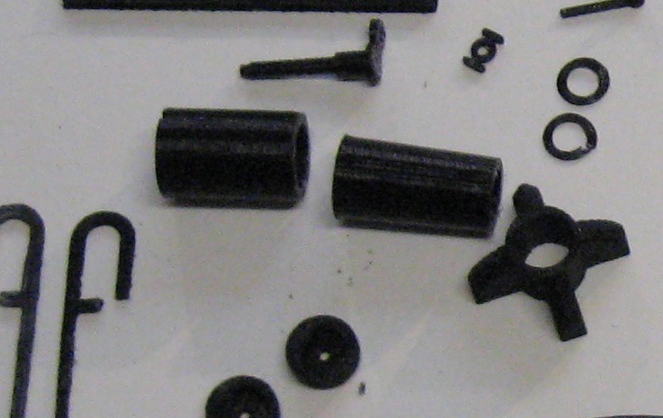
There were 54 different parts, some of which needed to be printed more than once ( eg two halves of the flywheel, the beam, the bearings, etc.) and so I worked out my printer was in action for 47 hours 1min. However, I am very pleased with the outcome.

The beam engine will be situated inside the engine house of the boneworks, which has a very large window and so will be highly visible.
For more information, see How I assembled a 3D printed beam engine

Once I started tinkering with it, I couldn't stop and after a couple of days the transportation for Lord Tollemache's eldest daughter was born.

For more information see How I made a car railcar.

I drew a side and an end for a luggage van to tow behind my recently finished County Donegal railcar - See How I constructed a CDR railcar - pending
The sides were printed out and some additional details added with plasticard and offcuts of brass section


The couplings have now been installed .......

..... and at the same time I tidied up the paintwork and added PLR emblems.

Z axis problem
A problem which surfaced when printing out parts for the beam engine is that there seems to be a bug in the firmware for the Z-axis. It's not insurmountable but somewhat irritating. The printhead seems unable to print anything taller than 36mm. I have tried several approaches to sort out the problem following suggestions on various 3D forums, all to no avail. Eventually, I may have to update the firmware but this might be difficult as I cannot get the printer to communicate directly with my laptop. In the meantime, I have been chopping taller parts into sections shorter than 36mm, printing out the sections and then gluing them back together again, such as the pillar for the beam engine.

I see this as an inconvenience rather than a major problem - after all, the printer only cost me £80, so I must expect some teething problems.

Lineside
Boneworks
Work has been progressing steadily on the boneworks which will be situated on the new siding at Bulkeley station. The model is based on the Bone and Flint Mill at Etruria in Stoke on Trent.
The concrete base on which will sit has been cast ......

..... and the walls have been scribed with brickwork.

The roof has been tiled .......

..... and the window frames and ridge tiles have been drawn in TinkerCAD (see How I drew window frames for 3D printing with TinkerCAD) .......

....... and printed out.

The next stage will be painting and final assembly. Hopefully, not far to go now.

Beam engine
In the meantime, I downloaded and printed out the parts needed to make a beam engine from the Thingiverse website.There were 54 different parts, some of which needed to be printed more than once ( eg two halves of the flywheel, the beam, the bearings, etc.) and so I worked out my printer was in action for 47 hours 1min. However, I am very pleased with the outcome.

The beam engine will be situated inside the engine house of the boneworks, which has a very large window and so will be highly visible.
For more information, see How I assembled a 3D printed beam engine
Rolling stock
With over 70 items of good rolling stock, six coaches and 18 locos, the Peckforton Light Railway has probably reached maximum capacity, however I find it difficult to resist the temptation to add another item of stock when something takes my fancy.Car railcar
When tidying my shelves I came across a dismembered car railcar which I had picked up on eBay a couple or more years ago. As bought, it was mounted very high above the track with an over-sized bogie supporting the front end. I had shelved it with the intention of finding a way of modifying it to sit lower on the track.
Once I started tinkering with it, I couldn't stop and after a couple of days the transportation for Lord Tollemache's eldest daughter was born.

For more information see How I made a car railcar.
Luggage van
Having got to grips with creating my own 3D drawings with TinkerCAD, I decided to try drawing something a bit more ambitious.
I drew a side and an end for a luggage van to tow behind my recently finished County Donegal railcar - See How I constructed a CDR railcar - pending
The sides were printed out and some additional details added with plasticard and offcuts of brass section

Couplings for Maddison coaches
For the past two years I have been steadily replacing LGB plastic couplings on all my rolling stock with my own slimline wire and brass rod versions. The last three items of rolling stock to be converted were the Maddison coaches. In addition to adding couplings, I needed to mount buffers on swivelling arms attached to the bogies. At the same time, I increased the distance between the coaches to enable them to negotiate the tightest curves on my railway as previously the coach roofs touched.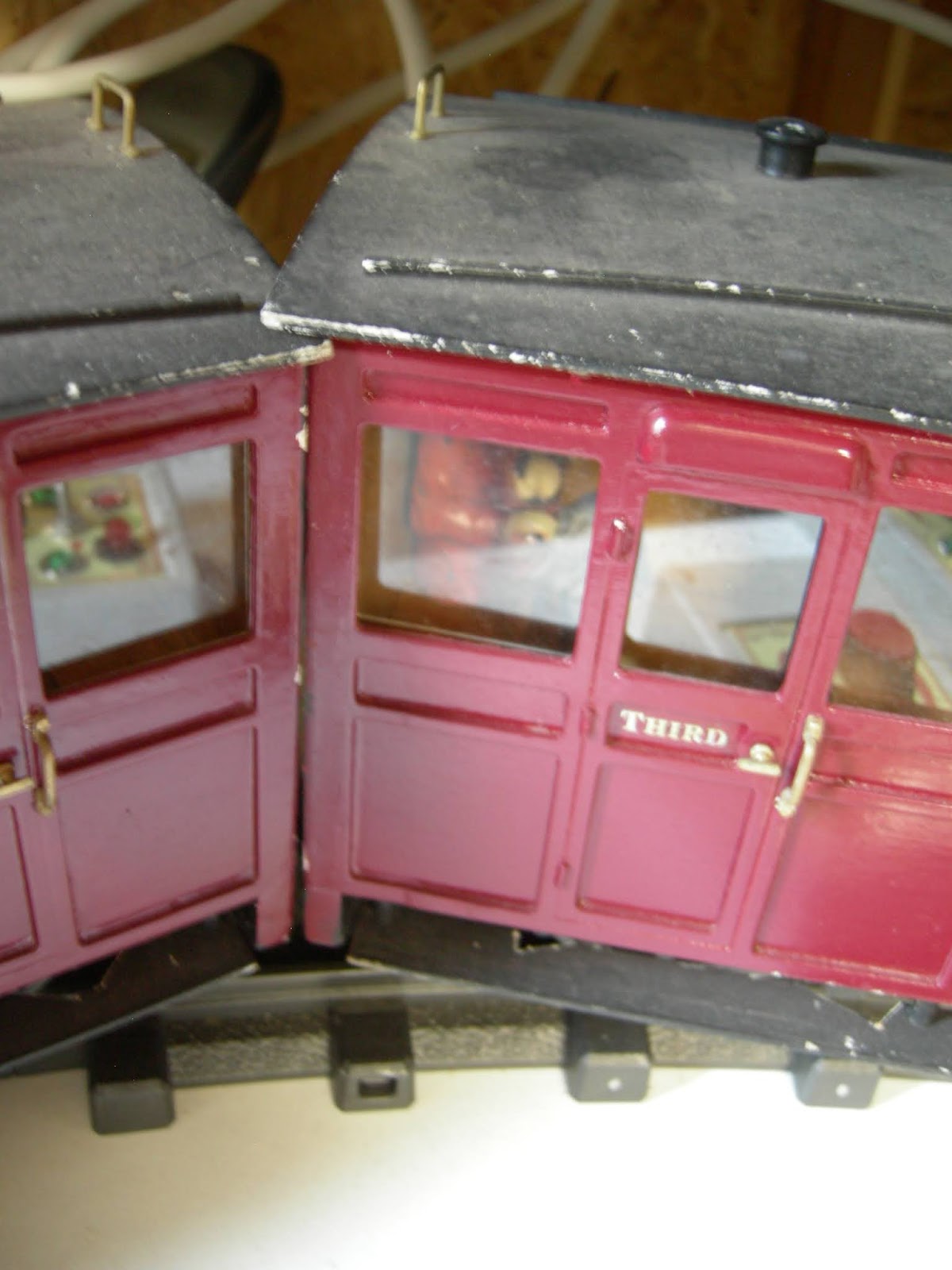
The couplings have now been installed .......

..... and at the same time I tidied up the paintwork and added PLR emblems.

Other
3D printer
As indicated above, I have been pressing my 3D printer into service on a range of projects. I have also been steadily adding enhancements such as a Y-belt tensioner, a cooling duct for the printhead and a glass print-bed.
[Awaiting photo]
Z axis problem
A problem which surfaced when printing out parts for the beam engine is that there seems to be a bug in the firmware for the Z-axis. It's not insurmountable but somewhat irritating. The printhead seems unable to print anything taller than 36mm. I have tried several approaches to sort out the problem following suggestions on various 3D forums, all to no avail. Eventually, I may have to update the firmware but this might be difficult as I cannot get the printer to communicate directly with my laptop. In the meantime, I have been chopping taller parts into sections shorter than 36mm, printing out the sections and then gluing them back together again, such as the pillar for the beam engine.
I see this as an inconvenience rather than a major problem - after all, the printer only cost me £80, so I must expect some teething problems.


