However, I have been able to take time out from my commitments to work on various projects:
Rolling Stock
I have been tempted to acquire or construct new items of goods or passenger rolling stock, but the storage roads in the garage (see How I constructed storage sidings) ........

...... are now full to capacity and so it is more likely that, in the future, I will start super-detailing wagons and coaches and maybe replace some items with better alternatives.
As my locos are stored in the house, I have been able to add a couple more locos and, as part of my RC Trains activities, I have converted a range of locos to battery power for various customers.
Regner Chaloner
Probably the most significant development is the acquisition of my first live steam locomotive. As slow-running and controllability are important considerations for my approach to operation, I decided a geared loco would be more appropriate. I was fortunate that a fellow modeller on one of the forums which I frequent offered me a Regner vertical boilered 'Chaloner' loco at a reasonable price.

She has so far had two outings on my railway and I am slowly getting to grips with the demands of a loco which requires fuel and water at regular intervals. My next plan is to install radio control so that she can be better integrated into my usual operating sessions. I appreciate that she is substantially over-scale (being nearer to 7/8ths scale), but have never been a rivet-counter often exercise the gentle art of compromise.
Angliscisation of Stainz
This project has been ongoing since the Summer. Although I could quite legitimately justified the running of a loco with German origins on my 1930s fictional rural narrow gauge railway (see A History of the Railway and its Locality), I decided to indulge in a bit of kit-bashing to turn her into something more Anglicised (see How I Anglicised my LGB Stainz loco).
 |
| LGB Stainz conversion - work in progress |
I have described previously how I converted her to battery power using a trail car (see How I converted an LGB Stainz loco to battery power with a trail car and How I converted an LGB Stainz loco to battery power without a trail car). In addition to changing her appearance, I replaced the large head and tail lights with more appropriate loco lamps (see How I made some loco lamps) and stripped out the circuit board to use the directional lighting outputs from the Deltang/RC Trains Rx65b receiver instead. I also replaced the simulated sandpaper-rasping default soundcard with a more sophisticated Dallee soundcard (see How I interfaced a Dallee soundcard with a Deltang / RC Trains Rx65b receiver/controller).
ToyTrain Diesel
Quite a few of my locos were constructed using LGB ToyTrain 0-4-0 motor blocks (eg see How I constructed a Hunslet loco from a GRS kit). I like to have at least one motor block 'in stock' as a spare or in case I have an urge to construct another locomotive. To this end, I bought a brand new LGB ToyTrain diesel loco for a reasonable price on eBay.
I am considering using this as the basis for another diesel outline loco - watch this space!
Soundcards
I must confess to being fascinated by soundcards and whenever one comes up on eBay I tend to place a tentative bid and then forget about it. In this way, I have recently acquired three soundcards - a couple of older versions of Dallee soundcards (one diesel and one steam) and a Phoenix BigSound 2k2 soundcard.

I am also working with Alan Bond on developing a small soundcard for diesel locos, though this project has been on the back-burner since the summer. Maybe, now I have a little more free time, I can resurrect it.


Battery conversions
As indicated above, through my work with RC Trains, I was commissioned to convert customers' locos to battery power and/or radio control. For example:Piko loco
I converted a G Scale Piko DB BR80 loco so it could run either on battery power and radio control or from conventional DC track power - see How I converted a Piko DB BR80 loco to battery power.

I tried to make this loco uncomplicated and self-contained by using three 18650 li-ion batteries and an iMax B3 charger. However, one of the greatest problems was finding a suitable panel mounted four-way socket to link the charger to the loco.

I used a 3.5mm four-pole jack socket and plug but was not entirely happy about it as, if it is not inserted fully, it could cause problems with the charger connections. It was therefore never intended to be more than a one-off experiment.
PLine diesel loco
The greatest problem with this loco was finding space for the batteries. Some 'flat' li-ion phone batteries were a perfect fit but proved reluctant to have leads soldered to their contacts and so two14650 li-ion batteries were squeezed in under the bonnet together with a Deltang/RC Trains Rx65b receiver/controller.

She responded well to the receiver and seemed quite happy trundling around my SM32 copper mine tramway see - How I converted a manually controlled PLine Lister to radio control)

Dapol 0 Gauge Terrier Tank
This was a complete departure from my usual loco conversions and proved to be quite a challenge, as space was very limited inside the body. I did, however, manage to squeeze four 10440 (AAA sized) li-ion batteries into the side tanks (wired as two parallel pairs - 2S2P) and a Deltang Rx60b receiver/controller into the smokebox.

With her flywheel and superior motor and gearbox, she proved to be a very smooth runner - quite a tempting proposition if ever I decide to venture into 0 gauge ...... (get thee behind me Satan!).

Permanent Way
The layout of my railway is now quite firmly fixed and so developments with permanent way tend these days to be more associated with maintenance than track laying. However, there is always room for improvement and so there have been a few developments.Peckforton re-alignment
After widening Peckforton Station and laying a new siding (see How I enlarged Peckforton Station), I decided it was time I sorted out a long-standing problem with the main tracks passing through the station. Since creating the station (see How I added a new station at Peckforton), the concrete blocks on which the track was laid, have settled - causing an unwelcome dip. This has meant that pulling in and out the station is a bit of a challenge, particularly when using inertia control on the RC Trains/ Deltang transmitters and even more so with visiting live steam locos. Rather than lifting all the track and re-positioning the blocks, I opted for a less intrusive approach which I've used before - I removed the screws holding the track and replaced them with longer ones. The track was then temporarily raised on various pieces of slate, tile and stones ........
.......and the space beneath the track filled with concrete.

The dip has now been removed and it is a lot easier to control the stopping and starting of trains. Though the platform now also needs to be raised to allow the poor passengers to reach the steps up into the coaches.

Level crossing
Having acquired a level crossing kit from North Pilton Works, I installed one of the crossings on the approach to Peckforton Station.
As with all railways built under the Light Railways Act of 1896, the Peckforton Light Railway was constructed in the cheapest way possible. Instead of expensive over- and under-bridges, most of the road crossings would have been on the level. As a consequence, I have to find space for three more level crossings. Each North Pilton kit provides me with sufficient parts for two single track level crossings and so is proving to be a cost effective approach to solving this problem. All I need to do now, is find suitable locations for the remaining crossings. (see How I installed a level crossing)
Lineside
Picket fencing
In addition to the level crossing kit, I also invested in some picket fencing from the same supplier. Having tried (and failed) to make realistic picket fencing myself, I decided this laser-cut fencing was a cost effective solution. The kits come with a variety of different fittings, large gates. small gates, corner posts etc. and so I opted for a couple of kits with gates and an additional fencing pack. So far I have installed fencing around the forecourt of Beeston Market station (see How I installed some picket fencing ).......
People
Having set my fictional railway in a real life setting (rural Cheshire) and a specific time period (the early 1930s, I realised that I could actually give the passengers and railway staff real identities, based on the names and occupations of local inhabitants drawn from census returns. Unfortunately, as census data is only released on the 100th anniversary of a particular census, I shall have to wait another fourteen years until the 1931 census records are made available and so I have had to use some artistic/modellers'/historical/genealogical licence to use the returns from 1911 to give identities to the figures which populate the platforms, station yards and carriages (see How I created identities for my populace). For example, this chap is John Boote, the foreman of the sandstone quarry in Bickerton.
..... and this young lady ....

.... is Ann Kirby, the cook at Bulkeley Hall.
In addition, I have also acquired a clutch of new characters for my railway.

These will eventually be assigned names and personalities as they take up their places on the railway. My next aim is to search local newspaper archives to identify specific events which occurred at the time and then create life stories for some of the characters. Who says this hobby is uninteresting?
Operations
Operating sessions
I have managed a few operating sessions since the last Progress Report, but they have been few and far between. Mostly, operations have been restricted to testing converted locos or running a few unscheduled trains when visitors have arrived (see below). I did squeeze in a couple of timetable-led sessions during August and October, however - here are a few photos from one of them them. |
| Diesel loco No.8, Wynford on the first Down ore train of the day |
 |
| Manning Wardle 0-6-0T No.6 Harthill eases out of Beeston Market with the Down afternoon mixed |
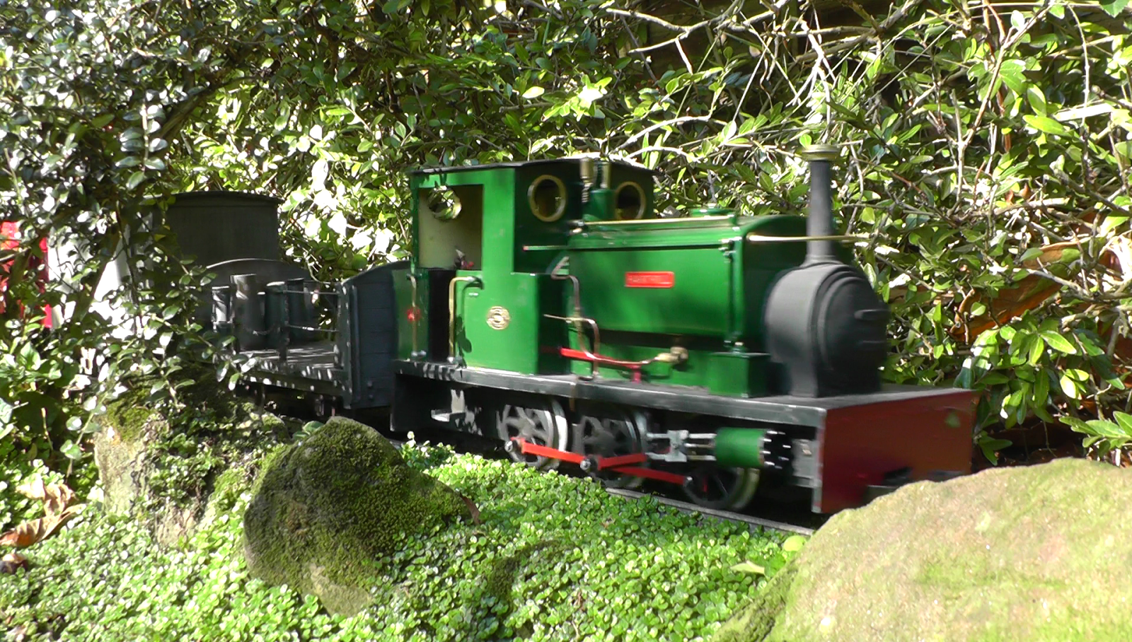 |
| No. 6 Harthill approaching Beeston Castle station with the Down mixed |
 |
| The Down afternoon mixed pauses at Bulkeley station to allow an Up ore train to pass, hauled by diesel mechanical Fowler loco No. 7 Tollemache |
 |
| Peckett 0-4-0 loco No.1 Peckforton taking the Up pick-up goods out of Bulkeley station across the swing bridge |
 |
| No.8 Wynford on an Up 'special' (taking stock back to the storage sidings) |
Visitors and visitations
 |
| Peter and his friend, Mike, preparing one of the Emett trains at Brockhampton Station |
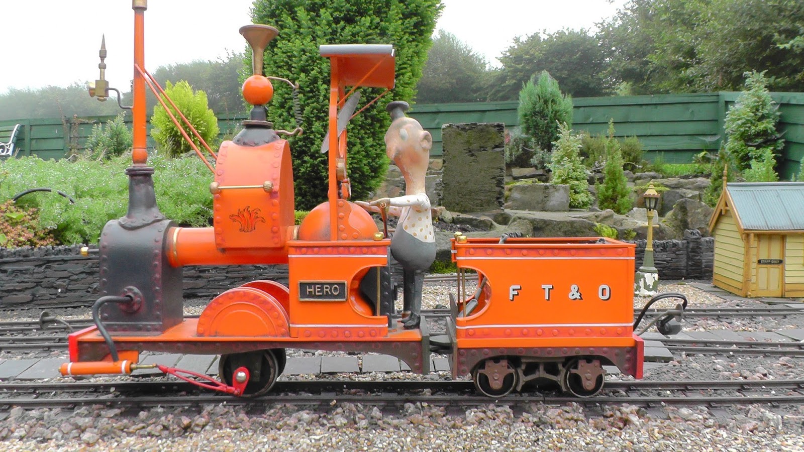 |
| 0-2-0 loco Hero |
 |
| 2-2-2 loco, Neptune |
 |
| 0-4-0 Steam Railmotor |
 |
| 0-4-0 loco No.5, Nellie, hauling the milk train |
During August, Zach Bond made what is becoming an annual visit, this time bringing his trusty Accucraft Excelsior (River Butley).

..... together with his 'momentum van'.

More recently, Phil Partridge's freelance battery powered diesel loco with a small collection of mineral wagons paid the line a visit.


It's always pleasant to welcome visitors and also to gain inspiration by visiting other people's railways.
Developments
Canal basin extension
I have been steadily accumulating lengths of track and pointwork in preparation for constructing an extended siding from Beeston Market station to reach the canal basin where, it is envisaged, there will be a run-round loop and a siding for transhipment of goods between canal boats and the railway.
RC Trains
After much deliberation, at the beginning of this month, I decided to hand over my online business supplying radio control equipment for trains to a fellow modeller and electronics enthusiast, Phil Partridge. With members of my family undergoing various medical procedures, I decided I could no longer care for them and keep the business going. I am confident that Phil will continue to develop the business and I can refocus my attention on my own railway and this blog (oh, and my family, of course!).


