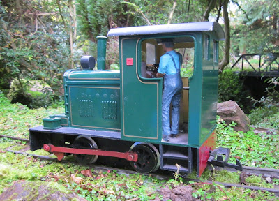
Since converting my semi-scratchbuilt Fowler diesel loco from track power to battery powered radio control (see How I converted my Fowler from track to battery power), I have been trying to decide which sound system to install.

I have previously used the rather fine MTroniks DigiSounds module from Peter Spoerer, which uses genuine digitised diesel sounds (see Adding a soundcard to a diesel loco), but I really wanted my two diesel locos to sound a bit different. I then stumbled across the Alan Bond / Technobots programmable soundcard. Although this doesn't use real digitised sounds, I was impressed by the realism of the synthesised sounds it creates in the videos which I found online (eg https://www.youtube.com/watch?v=vsIhu18zT_E ).
The card is neatly housed in a splashproof case as it was originally designed for use in boats.

However, the circuit board was easily removed by undoing four screws.

Although the card has a fairly small footprint, space was tight in my Fowler loco so the first task was to decide where the card could be located. I toyed with the idea of placing two of the 18650 li-ion batteries in the cab as I had done on a previous conversion (see How I converted my Peckett loco to battery power), however, they would have been more visible in this loco's cab unless I opted for the smaller 14500 batteries - which, of course, would have less capacity and hence would give shorter running times.
Eventually, I decided to install the card in the roof of the cab, where it fitted quite snugly.

The strange protuberances from the ceiling were actually not that noticeable and so I felt I could live with it.

Normally, I locate the speaker under the roof of the cab, to allow the sound to escape easily, but this option was now not available. Fortunately, when I constructed the loco, it was originally equipped with an inexpensive sound decoder and the speaker for this was mounted behind the radiator grille. A suitable 8 ohm speaker was purchased from Maplin (Code L68AA0 and squeezed into the space.

The next decision was how to trigger the soundcard. The Technobots card was designed to fit between a receiver and the ESC (Electronic Speed Controller), the lead from the receiver being plugged into the unit and then another lead (provided) connecting the soundcard to the ESC. The Deltang Rx65b, which is now my preferred receiver, has a combined receiver/ESC on a single circuit board and so the interface between the receiver and the ESC is not accessible. I figured I had four alternative approaches, three of which I tried and one I considered and rejected:
In addition to the basic wiring, The Rx102 was reprogrammed using a Deltang Prog 3 programmer to that Pin 5 produced a momentary 'off' output (ie 0v) in response to Channel 5 (ie the bind button on the transmitter) (see How to program Deltang receivers). A wire was then soldered to Pin 5 of the Rx102 and soldered to the Aux input pin of the soundcard.
 However, although the soundcard operated well, I was very disappointed with the level of control provided by the ESC. It was nowhere near as precise and controllable as the Deltang Rx65b, particularly at low speed. As I really enjoy slow running and shunting operations, this was not really something I could live with. I did consider buying another ESC to see if it provided more precise control, but that would risk shelling out more money and still maybe being disappointed with the outcome.

However, in practice I ran into a difficulty. While the output from the pad was sufficient to control the sound when the loco was running forwards, in reverse the card emitted a monotone sound unrelated to the speed of the loco. It looked as if, maybe, the 3.3v output from the receiver was insufficient to be detected by the card when running in reverse.


The sound synthesiser section of the soundcard normally uses the BEC input from the ESC to power its electronics and so, as I was not connecting it to a standalone ESC, I needed to provide the card with an alternative 5 volt supply. I constructed a simple circuit using an LM7805 voltage regulator and a capacitor following guidance provided online. Greg suggested adding a diode to the 5v output and then inserting a 1000uF capacitor in place of the 0.1uF ceramic capacitor for additional protection, but I didn't have a suitable capacitor to hand.
The components were soldered to a small piece of Vero board, together with the wires for connections (red = 12v input, black = 0v (negative), yellow = 5v output).

The board was then shrouded in heatshrink sleeve to avoid accidental short circuits.

The yellow wire from the regulator board was then soldered to the middle pin marked Ch1 on the soundcard board and the black wire inserted into the -ve terminal on the board. Another black wire was also taken from the -ve terminal and soldered to the outermost pin marked Ch1. The JST servo lead provided with the card was inserted into the other Ch1 socket on the circuit board .......

..... and connected to the Ch1 pins on the Rx102 receiver board. A wire was also soldered to the uppermost (signal) pin for Ch5 (ie pin 5) on the Rx102 board and the other end soldered to the innermost (signal) pin nearest the DIP switch block. This carries the signal from the Bind Button (Channel 5) on my DeltangTx22 transmitter to trigger the horn on the soundcard.

The red wire from the regulator board was inserted into the +ve terminal on the board, together with a red wire leading to the on/off switch on the loco. Another black wire from the loco battery negative supply was squeezed into the -ve terminal on the soundcard alongside the other two wires. The pink and purple wires (I like to colour code my wiring) from the speaker were inserted into the speaker terminals on the board.
The wiring to the speakers and the battery were taped to the back of the cab, the regulator and Rx102 receiver were tucked into the cavity in front of the driver and the board was positioned beneath the cab roof.

After checking that the card and loco were reliably operational, the loco was reassembled, and then taken out into the garden for a test run.
From some angles the soundcard and its wiring are barely visible (I've just noticed that the nameplate has fallen off ...... must be lurking in the undergrowth somewhere).

The wiring was a little more obvious from another angle ..... so maybe I will site the batteries in the cab after all.

Yes, the spaghetti is somewhat in your face (well the driver's) while a couple of 14500 batteries will be barely visible.

But, for the time being, ...... the proof of the pudding ..........
I turned the volume on the card down to about a quarter of its full setting in the video. The unit is designed to be heard across a large boating pond and so the sound does carry quite well across the garden (and into the neighbours'). Technobots market a smaller unit (at about half the price), which doesn't have the full programming features but does seem to have a similar sound to the one I selected on this unit. It also can be tailored to have 2-6 cylinders, which makes it sound (sorry) quite attractive should I decide to build another diesel loco (I have another motor block sitting on the shelf....).
In the meantime, I am more than pleased with the way this unit behaves. And if ever I get tired of this particular engine sound, I can always reprogram it at no extra cost!
UPDATE - 20/10/15
I decided that the clutter in the cab was unacceptable and so re-positioned the card and associated electronics in the engine compartment. I left one of the batteries in the compartment .....

...... and placed the other two in the front corners of the cab, painted dark brown to match the console.

The batteries are hardly noticeable .......

..... a lot less obtrusive than the electronics and wiring were. (Still not found the missing nameplate!).

I have previously used the rather fine MTroniks DigiSounds module from Peter Spoerer, which uses genuine digitised diesel sounds (see Adding a soundcard to a diesel loco), but I really wanted my two diesel locos to sound a bit different. I then stumbled across the Alan Bond / Technobots programmable soundcard. Although this doesn't use real digitised sounds, I was impressed by the realism of the synthesised sounds it creates in the videos which I found online (eg https://www.youtube.com/watch?v=vsIhu18zT_E ).
The card is neatly housed in a splashproof case as it was originally designed for use in boats.

However, the circuit board was easily removed by undoing four screws.

Although the card has a fairly small footprint, space was tight in my Fowler loco so the first task was to decide where the card could be located. I toyed with the idea of placing two of the 18650 li-ion batteries in the cab as I had done on a previous conversion (see How I converted my Peckett loco to battery power), however, they would have been more visible in this loco's cab unless I opted for the smaller 14500 batteries - which, of course, would have less capacity and hence would give shorter running times.
Eventually, I decided to install the card in the roof of the cab, where it fitted quite snugly.

The strange protuberances from the ceiling were actually not that noticeable and so I felt I could live with it.

Normally, I locate the speaker under the roof of the cab, to allow the sound to escape easily, but this option was now not available. Fortunately, when I constructed the loco, it was originally equipped with an inexpensive sound decoder and the speaker for this was mounted behind the radiator grille. A suitable 8 ohm speaker was purchased from Maplin (Code L68AA0 and squeezed into the space.

The next decision was how to trigger the soundcard. The Technobots card was designed to fit between a receiver and the ESC (Electronic Speed Controller), the lead from the receiver being plugged into the unit and then another lead (provided) connecting the soundcard to the ESC. The Deltang Rx65b, which is now my preferred receiver, has a combined receiver/ESC on a single circuit board and so the interface between the receiver and the ESC is not accessible. I figured I had four alternative approaches, three of which I tried and one I considered and rejected:
- Use a Deltang Rx102 receiver and a third party ESC (I had a spare ESC to hand) and connect the card between the two as per the design
- Find some way of dynamically outputting the motor settings from the Deltang Rx65b to the card
- Find some way of inputting the PWM signal for the motor from the Deltang Rx65b to the soundcard
- Use a Deltang Rx102 receiver to control the soundcard and the Deltang Rx65b receiver/ESC to control the loco motor, making sure both were bound to the transmitter.
1. Using a Deltang Rx102 and a separate ESC
This was by far the easiest option. The Rx102 was bound to the transmitter and a standard servo connector taken from it to the soundcard. The ESC was wired into the system and connected to the battery and the motor. The soundcard drew its power from the ESC and so everything was installed quite quickly.In addition to the basic wiring, The Rx102 was reprogrammed using a Deltang Prog 3 programmer to that Pin 5 produced a momentary 'off' output (ie 0v) in response to Channel 5 (ie the bind button on the transmitter) (see How to program Deltang receivers). A wire was then soldered to Pin 5 of the Rx102 and soldered to the Aux input pin of the soundcard.

2. Outputting the motor settings from a Deltang Rx65b to the card
As well as its controllability, another great virtue of the Deltang Rx65 is the number of output pads it provides (12), all of which can be re-programmed. Pad 8 on the Rx65b comes ready-programmed to output Channel 1's servo settings. This was therefore ideal, as Channel 1 is used to control the motor speed. Pad 12 was reprogrammed with my Tx20 transmitter to provide 0v momentary output in response the Channel 5.
However, in practice I ran into a difficulty. While the output from the pad was sufficient to control the sound when the loco was running forwards, in reverse the card emitted a monotone sound unrelated to the speed of the loco. It looked as if, maybe, the 3.3v output from the receiver was insufficient to be detected by the card when running in reverse.
3. Finding some way of inputting the PWM signal for the motor from the Deltang Rx65b to the soundcard
This solution was feasible. The soundcard is designed to receive input from a potentiometer and so an electronic circuit could be designed to take the PWM (Pulse Width Modulated) output for the motor from the Deltang Rx65b and convert it into something which the soundcard could recognise. However, whilst I had access to expertise (Alan Bond (the soundcard developer) and Greg Hunter (of the Sandstone and Termite Railway)) both of whom volunteered to advise, I felt this was making the project too complicated for replication by others. It would also require a separate battery supply (unless I made the circuit even more complicated) and with space at a premium, it looked as if this approach was going to create more problems than it solved.
4. Using a Deltang Rx102 to control the soundcard and a Deltang Rx65b to control the loco motor
In the end, this is the approach I adopted. I get the best of both worlds - the precise control and the host of features which the Deltang Rx65b brings, together with the ease of installation which the Deltang Rx102 provides. Both receivers are bound to the same Selecta channel on my Deltang Tx22 transmitter and so the Tx simultaneously controls both receivers. A 5v regulator circuit (see below) was needed to provide power for the synthesiser part of the soundcard, but this was a lot less complicated to construct than the circuit needed for option 3 above.
Installation
As indicated above, the card fitted neatly into the roof of the cab and the speaker sat snugly behind the radiator grille. All I needed to do now was wire everything up. |
| Source: http://www3.nd.edu/~lemmon/courses/ee224/web-manual/web-manual/lab8b/node6.html |

The board was then shrouded in heatshrink sleeve to avoid accidental short circuits.

The yellow wire from the regulator board was then soldered to the middle pin marked Ch1 on the soundcard board and the black wire inserted into the -ve terminal on the board. Another black wire was also taken from the -ve terminal and soldered to the outermost pin marked Ch1. The JST servo lead provided with the card was inserted into the other Ch1 socket on the circuit board .......

..... and connected to the Ch1 pins on the Rx102 receiver board. A wire was also soldered to the uppermost (signal) pin for Ch5 (ie pin 5) on the Rx102 board and the other end soldered to the innermost (signal) pin nearest the DIP switch block. This carries the signal from the Bind Button (Channel 5) on my DeltangTx22 transmitter to trigger the horn on the soundcard.

The red wire from the regulator board was inserted into the +ve terminal on the board, together with a red wire leading to the on/off switch on the loco. Another black wire from the loco battery negative supply was squeezed into the -ve terminal on the soundcard alongside the other two wires. The pink and purple wires (I like to colour code my wiring) from the speaker were inserted into the speaker terminals on the board.
The wiring to the speakers and the battery were taped to the back of the cab, the regulator and Rx102 receiver were tucked into the cavity in front of the driver and the board was positioned beneath the cab roof.

After checking that the card and loco were reliably operational, the loco was reassembled, and then taken out into the garden for a test run.
From some angles the soundcard and its wiring are barely visible (I've just noticed that the nameplate has fallen off ...... must be lurking in the undergrowth somewhere).

The wiring was a little more obvious from another angle ..... so maybe I will site the batteries in the cab after all.

Yes, the spaghetti is somewhat in your face (well the driver's) while a couple of 14500 batteries will be barely visible.

But, for the time being, ...... the proof of the pudding ..........
I turned the volume on the card down to about a quarter of its full setting in the video. The unit is designed to be heard across a large boating pond and so the sound does carry quite well across the garden (and into the neighbours'). Technobots market a smaller unit (at about half the price), which doesn't have the full programming features but does seem to have a similar sound to the one I selected on this unit. It also can be tailored to have 2-6 cylinders, which makes it sound (sorry) quite attractive should I decide to build another diesel loco (I have another motor block sitting on the shelf....).
In the meantime, I am more than pleased with the way this unit behaves. And if ever I get tired of this particular engine sound, I can always reprogram it at no extra cost!
UPDATE - 20/10/15
I decided that the clutter in the cab was unacceptable and so re-positioned the card and associated electronics in the engine compartment. I left one of the batteries in the compartment .....

...... and placed the other two in the front corners of the cab, painted dark brown to match the console.

The batteries are hardly noticeable .......

..... a lot less obtrusive than the electronics and wiring were. (Still not found the missing nameplate!).


