Showing posts with label Fowler diesel loco. Show all posts

Monday, September 21, 2015

How I converted my Fowler diesel to battery radio control

My first scratchbuilt loco was a diesel mechanical loco based on a cross between a standard gauge and a 2' gauge Fowler loco (see How I constructed an early Fowler diesel locomotive). I had been unable to find a 3' gauge Fowler and so surmised it would look similar to their standard gauge locos - albeit smaller.

 When I changed from DCC track power to battery powered radio control, I constructed several locos to be purely battery powered and slowly converted my previously track powered locos to battery power. This particular loco had been sitting on the shelf, awaiting conversion to battery power, for around two years. Her duties were being discharged by my IP Engineering Jessie (Loco No. 8, Wynford) and so there was no immediate need for Tollemache's conversion. I kept putting it off as I knew I'd have to sort out the flycranks which had been a problem during construction. Ultimately, the solution of this problem was a lot easier than I expected (see How I increased the offset of some GRS whitemetal flycranks).

With this problem solved, the path was paved for the loco's conversion to battery power.

 The LGB ToyTrain 0-4-0 motor block was separated from the body and taken apart to remove the wheel and track electrical pickups. I have described this process previously (see How I converted my GRS Peckett to battery power).

 To create space in the engine compartment of the loco, I had to remove the lead flashing to accommodate the three tagged 18650 li-ion batteries which were soldered together in series to provide the 11.1 volts power supply.
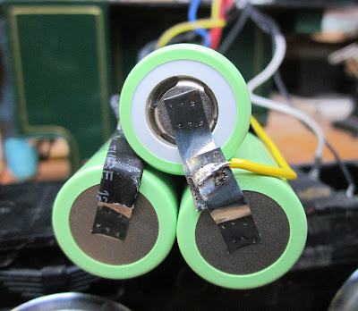
This battery pack was then connected to a li-ion battery protection board (see circuit diagram below) which had been bought from China via eBay  ......

 A 3S balance charge socket was also soldered into the circuit to allow the charge levels in the individual cells to be measured.
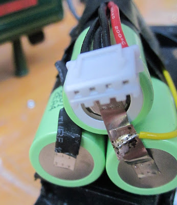
The charge socket and two-way switch were wired-up with connections to the output terminals on the protection board.

 The switch and socket were then installed in holes drilled in the instrument panel of the loco cab.

 The positive input lead to the Deltang Rx65a was then connected to the switch and the negative lead to the supply contact on the protection board. A lead was also soldered to Pad 2 on the receiver board. This is the output for the rear directional light (my locos are all reverse wired for directional lighting because the first locos I wired-up were all accidentally reverse wired). This lead was then connected to the headlamp LED.

 The incandescent bulb in the headlamp was removed and a bright white LED inserted into the socket (this was actually the most difficult and time consuming stage of the conversion). A 470ohm resistor was then wired into the supply lead for the LED before being connected to the output from the board. The other lead from the LED was connected to the negative terminal on the protection board.

The wiring was then tested by turning on the power switch and binding the receiver to the Tx22 transmitter. The circuit boards and batteries were then insulated with insulation tape to avoid accidental short circuits when the components were squeezed into the engine compartment.

After test-fitting the components, I realised there was some available space to re-instal some of the lead flashing. This was trimmed to size and glued to the sides and roof of the engine compartment with clear Bostik adhesive.

To summarise, the circuit diagram for the conversion indicates how the components were connected. The four leads for the balance charge socket were soldered to the four connections for the batteries on the protection board making sure the order of connections to the batteries was preserved (from positive (red lead) to negative (final black lead)).

The loco was reassembled ..........

...... and then given a few test runs.

Although she has quite good hauling power (as can be seen from the video), I would like to install a little more weight as there is some wheel spin on my 1:40 gradients when hauling a full load. It might be possible to install a couple more pieces of lead flashing in the engine compartment but I will probably also find a few nooks and crannies to add a few more pieces of lead.

Overall, I am delighted to have this loco back in service. She has now been fully recharged and seems to be very controllable. For now, I feel I have sufficient locos to run services on my railway - but who knows whether I might see another prototype which seizes my attention??

How I increased the offset of my GRS whitemetal flycranks

Recently, I converted the last of my track powered locomotives to battery power (see How I converted my Fowler diesel to battery r/c). Fowler(ish) Loco No. 7, Tollemache, was the first loco which I scratchbuilt and so has particular poignancy for me (see How I constructed an early Fowler diesel locomotive).

During the build, I had a major problem with the layshaft. The only flycranks I could find (from Garden Railway Specialists - GRS), had 8mm offsets but the cranks on Tollemache's drivers had 10mm offsets. I solved the problem at the time by slotting the connecting rod to compensate for the 2mm differences at each end of the rotation.

This, of course, meant the motion was very sloppy which was especially notable when the loco was running at low speed. I don't have any video of this - I wonder why.....?

 I searched websites of various suppliers (eg GRS, Essel, Roundhouse, Brandbright) to see if anyone was marketing flycranks with 10mm centres, but to no avail. I considered making my own from brass, but precision metalworking is not one of my strengths. Then, inspirationally, I remembered that I had recently acquired skills in soldering whitemetal (see How I constructed an IP Engineering Plate Frame Simplex). The GRS flycranks were whitemetal.

The head of the crank was excised with a razor saw.

The ends of the two pieces were coated in flux, tinned with low-melt solder and then joined together with a 2.5mm fillet of solder (0.5mm to allow for the width of the saw blade).

The solder was then filed to shape - et voila, one fly crank with 10mm centres!

The slotted connecting rods were discarded and two more connecting rods cut from brass strip. These were then bolted on to the wheels and to the new flycranks which had been quartered and fixed on to the layshaft with cyano gel.

 The motion is now a lot smoother and so I am more than happy to video the loco moving slowly while, for example, shunting in the Copper Mine sidings.


Tuesday, April 10, 2012

Progress Report 40

For me, Easter has always heralded the start of the running season. This is largely because of the weather but also because until recently I had a fairly time-consuming job and hence any garden railway modelling had to fit into whatever daylight hours were available to me - which of course are fewer during the winter months. Although I am now semi-retired, a combination of family, household and work-related events have conspired to prevent me from spending as much time on the railway as I would have liked over the winter period and through the Easter vacation. However, there have been some developments on which I can report.

Into Print!


Following an editorial plea from, Tag Gorton, the former editor of Garden Rail for articles on 45mm gauge garden railways, I produced s story outlining the development of my railway. This was published in the March edition of the magazine.

The title for the article, Timetabled to Peckforton, was devised by the editor who enjoys wordplay (Timetabled to Perfection?). I provided the editor with far more pictures of the railway than would be needed and am very pleased with the selection which was made.
 This was the second article I have had published in GR, the first appearing in April 2011. This focused on the construction of the swing bridge, based on the original bridge over the River Blyth at Southwold.

I have posted an explanation of the construction techniques on this blog and also created a short Youtube video showing how I used uPVC trim and superglue to create the model.

I have another article on timetabling  and freight handling which is presently being considered by GR for publication and am considering writing further articles.

The Railmotor
It has taken quite a while but I have very nearly completed the construction of the railmotor and trailer. Unlike my other locos, which are track-powered, this is battery powered and controlled with a wireless keyfob controller. (See Youtube video) This was bought over the internet and was designed to fade 12v LED lighting systems. Whilst control using the unit is not high fidelity, for the price (around £15ukp), I am very pleased with the outcome.


Clearly, the models are not quite finished; they require a paint-job and I need to improve the internal lighting system. But the models look quite effective pottering around on the railway and provide me with something I can run at a moment's notice without the hassle of arduous track cleaning.

The Garden
One of the non railway developments which has been occupying my time over the past few months has indirectly affected the railway. We have had a garage built on what was formerly the front garden and as a consequence the back garden has now been extended.  Whereas previously, Beeston Market station was constructed adjacent to the fence dividing the front and back gardens.........


......... this fence has now been removed. Furthermore, clearance of undergrowth bordering the front garden and the erection of a new fence has led to some additional space being created in the back garden beyond the end of Beeston Market station.


I am in the process of considering how this increase in real estate might impinge upon the railway. Do I re-site the terminus, do I re-site the copper mine or do I build an additional branch to the canal basin which runs alongside the mythical location of Beeston Market station?

Guide to UK Narrow Gauge Railways
Something I have been researching over the winter months has been UK narrow gauge railways. I intend to visit as many of these as possible over the coming years and document the results of my travels on a blog - Narrow Gauge Railways UK.

Although I have already visited many narrow gauge railways over the years, I have never properly recorded these expeditions. This new blog will enable me to become more systematic in logging the outcomes of my visits.

So far, all my energies have been expended in researching the locations, opening hours and some of the background to the various railways around the country. Although I have restricted my attention to narrow gauge and miniature railways which have a gauge of one foot or greater, there are still around 180 operating railways which fit these parameters. This does not include the sites of narrow gauge railways which have closed (eg the Southwold and the Leek & Manifold).

Running repairs
Inevitably, as with full scale railways, ongoing maintenance and construction often dominates the winter period. You will see from the previous progress report (see Progress Report 39) that I had identified a list of repairs and construction projects.

Cattle wagons
The four cattle wagons owned by the railway were excessively heavy for my poor little 0-4-0 track-powered locos. Although my plasticard scratchbuilt cattle wagons were originally quite lightweight, the addition of Schleich cattle greatly increased the weight meaning that the locos struggled to pull the wagons up the inclines when they were included in freight trains. Either the cattle would have to be removed or I'd have to slim them down in some way. I decided on the latter, hollowing out the cattle from the underside with a powered drill.


The two IP Engineering wagons were also overweight form my railway. To reduce their weight, the steel roofs have been replaced with preformed plasticard (from GRS).


Fowler diesel
Close scrutiny of the video showing freight movements on the railway shows that the layshaft on the scratchbuilt Fowler diesel had become out of synch (see 6m 52sec into video). This is because the fly-cranks were superglued to the layshaft and after a while worked loose. The was remedied by re-quartering the cranks and then supergluing them back in place. If the problem persists, a more reliable method of fixing the cranks in place will have to be found. (See How I constructed a Fowler diesel)

Hunslet loco
After adding the power buffer to the Hunslet loco, the body was glued back together but was never quite as secure as when it was first constructed. A spectacular derailment on the elevated section of the line led to further unplanned dismantlement. The loco has now been reassembled but does require some remedial painting to tidy it up. This will be done prior to weathering the loco - another job on the list. (See How I constructed a Hunslet loco from a GRS kit)

Rolling stock
Some off-season purchasing has plugged a couple of gaps in the good stock.

Crane wagon
I've been considering constructing a crane wagon for use on the railway - to handle heavy loads on the railway and act as a breakdown and maintenance wagon by the permanent way department. A chance visit to a certain online auction website resulted in the purchase of a ToyTrain crane wagon. Whilst not, to my knowledge, based on a UK prototype I've decided to use it until something more realistic can be constructed. I'm presently undecided as to whether it is resprayed in PLR livery or whether to leave it in pristine condition to enhance its resale potential.


Closed van
Through contacts on the G Scale Central forum, I purchased an LGB closed van which had been sprayed oxide. I'm undecided as to its future but an wondering whether it should become a private owner wagon maybe for the company bottling the local mineral waters.


Gunpowder van
During last year's operating sessions, I identified the need for a gunpowder van to transport explosives to the copper mine. I became aware of a new model of a corrugated van from Swift Sixteen Models. This was purchased from the company's stand at the Association of 16mm NGM's annual show at Peterborough.


Although this is not based on any particular prototype, I feel the model more than fits the bill for a gunpowder van.

Monday, May 02, 2011

Progress Report 35

Taming the flora
Easter for me always marks the time for taming the garden and doing the running repairs on the the track needed for the coming season. This year, plant growth seems to have been quite vigorous.


An afternoon was spent in weeding the trackbed, cutting back overhanging plant-life and cleaning the track. I actually like the way the ballast has disappeared beneath moss and Mind Your Own Business. It contributes to the slightly neglected look which I am trying to engender.


Troublesome track
When I eventually I had cleared and cleaned as much as I could and powered up the electrics there was a short circuit somewhere in the largest electrical section. After first eliminating the most obvious possible causes, such as a tool being left across the track, I decided the problem must lie with one of the points - but which one?

I decided to narrow the search down by creating some smaller sections by sawing through the track midway between each station (Beeston Market, Beeston Castle and Peckforton). The multimeter revealed the fault was somewhere in the pointwork at Peckforton Station. Close scrutiny of each point revealed nothing so, before lifting them, I wriggled each one too see if that would do something useful - to my amazement it did. When I wriggled the leading point at the Beeston Castle end of the station the short circuit disappeared. Clearly, some insulation had broken down somewhere beneath the point. Although this has cured the problem for now, I know that sometime in the not too distant future I will have to lift this point and give it a thorough overhaul.

A test run with loco No. 1 revealed further problems with this point and with most of the other LGB R3 points on the system. The connection had broken down between the point blade and the rail leading the frog. The multimeter revealed that several other points were suffering the same complaint and also that with some the connection had broken down between the stock rail and the rail leading to the frog.

Another problem with the R3 points is that the gap between the check rail is too large. This means that sometimes rolling stock derails when taking the curved route through the point. I decided it was time to do some remediation work (see How I improved LGB R3 points - pending).

Buffer stops
Until now, seven sidings have been without buffer stops. Over the past year or so I've been steadily acquiring LGB rail-built buffer stops. I had considered making my own but was uncertain as to how to bend the rail in the vertical plane.


The tail of the LGB stops were shortened slightly to make them look more realistic and to maximise the length of the sidings.


I decided that the two sidings at Beeston Market which serve the engine shed (yet to be constructed) would not require buffer stops as they would terminate inside the shed.


A new loco joins the roster
I completed the conversion of the Toytain diesel into a representation of an early Fowler diesel mechanical locomotive. (see How I converted a Playmobil diesel into and early Fowler). Apparently, Fowler did produce a three foot gauge 2-4-0 diesel as well as their two foot gauge and standard gauge 0-4-0 diesels. My model attempts to show what a three foot gauge 0-4-0 would have looked like had they produced one.


I thought for a while about the livery for this loco. I wondered whether the Copper Mine might be independent of the rest of the railway and hence have its own stock and hence its own livery. However, on reflection I reasoned that as my imagined history of the railway owed its origins and continued existence to the copper mine, the rolling stock and locomotives used for this traffic would be integral to the railway as a whole. As a consequence, the new loco would be the property of the railway and would therefore be decked out in the same livery. This being the case, it would need a number and a name. The existing four steam locos had already been assigned names and numbers:
No. 1 - Peckforton
No. 2 - Beeston
No. 3 - Bickerton
No. 4 - Bulkeley
The villages served by the railway had already been assigned so, what should I call the new loco? I decided that it would be named in honour of the railway's hypothetical benefactor, Lord Bentley Tollemache. His full name was too long to fit into a nameplate and so it was decided the loco will be called simply Tollemache and given the number 7.

For more information on the imagined history of the railway see - A brief history of the railway and its locality.

Weathering rolling stock
I also got around to weathering and rusting a rake of loaded tippler wagons (see How I created a rake of loaded tippler wagons) to match the rake of weathered empty tipplers (see How I weathered a rake of LGB tipplers). Over the years I managed to accumulate two rakes of eight wagons and, in the last year, I acquired another couple of tipplers to make two rakes of nine. With a brake van, plus loco, nine tipplers comfortably fit into the run-round and passing loops on the line.


Figures
A visit to the 16mm NGRM Association's annual show in Stoneleigh resulted in the arrival of eleven new figures courtesy of Model Town.


These are in the process of being painted (see How I painted some figures) and will be strategically deployed around the line.

Running sessions
The weather has been glorious for the past week or so and as a consequence I've had several really good running sessions.


 This is the first time I've had four locos running in the railway's livery.


Inevitably, a few snags have been revealed. In addition to the poor connections in some of the R3 points, one of the coaches became derailed with monotonous regularity. The problem arose from the screws acting as pivots for the bogies: too tight and the bogies wouldn't follow the curves, especially through pointwork; too loose and the body rocked too much from side to side, lifting the wheels from the track on curves. The problem was solved by adding small wooden blocks to act as bearers between the bogie frames and the base of the coach.

In trying to make a video of the new Fowler diesel in action, I found it very difficult to keep the loco at a steady and realistic speed. I decided it must be something to do with the old style MRC decoder I'd installed. I replaced it with a newer LGB 55021 decoder. Result! The loco is now far more controllable and can be slowed to a crawl. Furthermore, as the new decoder takes up less room, I managed to cram some more strips of lead under the bonnet. The loco now handles its train of nine loaded tipplers without wheelspin.


Looking at the video I have come to realise that my trackbed is far more undulating than I thought. Some of this may be down to a lack of consistency in my original construction techniques but I suspect that some of the blocks have sunk over the past five years. It has made me realise how important it is to firm the foundation for the trackbed. I suppose I could have bedded the concrete/breeze blocks on to concrete, but my motivation originally was that laying them on sand/soil would be more flexible should I ever decide to change my plans.

Fauna
One of the joys of garden railway modelling is the opportunity it provides for working outdoors while pursuing a hobby. Over the past few days I have been joined and observed, not only by our cat, but also by a robin which seems to have taken over our garden as its territory.


During one of my running sessions, the robin spent most of the day flitting from one vantage point to another warning me that the cat was nearby.


On one occasion, while I was doing a wheel cleaning session in the conservatory, the robin flew in, but panicked when it couldn't find its way out again. I managed to catch it and release it.

Future plans
I'm not sure I will ever finish the railway - there's always plenty to do. The most pressing jobs are:
  • Constructing the engine shed at Beeston Market
  • Constructing the workshops and hoppers at the copper mine
  • Converting the Zillertal 0-4-2 into a Manning Wardle loco similar to Southwold Railway's Wenhaston
  • Detailing the stations with more people and general clutter
  • Constructing a few more items of goods rolling stock - eg some flat wagons, a gunpowder van