A few things have developed since my last report at the end of May. On the motive power front, he most significant has been the completion of the railway's twelfth locomotive, a Simplex diesel (Emma). Further, on the motive power front, various locos have been through the workshops for routine maintenance and, in the case of Manning Wardle Loco No. 6 (Harthill), some modification. In addition, Hunslet loco No. 3 (Bickerton) is in the process of being converted from track to battery power
There have been some developments with rolling stock - four new wagons have entered service and a couple of these, plus another two wagons, have been weathered.
The track has received some attention with, in particular, ballasting in and around the Copper Mine. There has also been ongoing track maintenance around the railway though this year, having gone over completely to battery power, the maintenance has been less onerous - there being no need now to worry about electrical continuity through the whole network.
Some lineside work has also been carried out, though on a limited scale compared with other developments. The staithes in the coal yard have now been completed, as has the plate girder bridge carrying the feeder line over the sidings at the Copper Mine. I have also, at long last, replaced the fencing separating the Copper Mine sidings from the main line.
History has been made - a live steam locomotive has run on Peckforton Light Railway metals for the first time - and finally, I have also managed to run some trains.

... I decided to modify it by adding more detail to the engine compartment and adding a cab.

Paint-finish
I experimented with a different type of paint-finish on this loco. After applying the primer, I applied rust colour to those areas which I thought would be most susceptible and then sprinkled crushed sea salt crystals on. After a couple of coats of the final colour, the rusty areas were abraded slightly to remove the paint and then rinsed in warm water, exposing the rust colour beneath apparently peeling paint. Some of the salt is still present under the top coat, but this gives the impression of rust bubbling up beneath. I'm not certain I have perfected the technique as yet, but to my mind it does seem to give a reasonable impression of corrosion.

Power and control
She has been equipped with two 14500 (AA sized) li-ion batteries wired in parallel to give extended running time. She also has a Deltang Rx65b receiver/controller which is hidden in the double wall of the cab side (nearest the camera in the above photo). I felt the receiver would be more reliable if placed in a plasticard cab than under the whitemetal bonnet of the engine compartment.

Sound system
I have also provided her with a very basic sound system, using a small module intended for use inside musical greetings cards.(see How I modified a greetings card sound module). The unit was cut down to remove the on-board batteries so it would fit inside the engine compartment, and then wired into the batteries of the loco. Whilst the sound is not remarkable, it does add an little something extra - and for under £1.50 (UKP) it certainly seems good value for money.
Chain drive
For a while, I ran the 45mm gauge chassis unaltered and was not overly impressed with the loco's hauling capabilities (3 or four skips on the level and down hill) -
However, after adding chain drive to turn her into a 4x4.....

..... the difference was, to my mind, quite amazing.
For more detailed information on the construction of this loco see - How I constructed a plate frame Simplex from an IP Engineering kit
Loco No. 3 Hunslet 0-4-0 - Bickerton
This is presently in the process of being converted. Her saddle tank was crammed full of lead weights to make her a whacking 2.2kg and I have been putting off tackling her conversion as I knew I would have to remove these weights to create space for the batteries. As she was constructed from a Garden Railway Specialists (GRS) resin kit, I was very concerned about dismantling her in case I damaged the fragile castings and yet the only way of removing the weights was to dismantle her into her various cast components.

I was pleasantly surprised to find that once I started prising apart the epoxied boiler assembly from the running plate and cab with a flat-bladed screwdriver, the two main components came apart quite easily with no irreparable damage. Furthermore, the clear Bostik adhesive holding the lead weights also parted with a little persuasion and so the loco is now ready for the next stage of conversion.

I found there was room in the saddle tank for three 3Ah 18650 tagged li-ion batteries with room to spare for some sheets of lead flashing. The battery protection board will fit into to lower half of the boiler and when funds permit, I will install the Deltang rx65b receiver/ controller into the firebox.
When she has been reconstructed an opportunity will be taken to give her a respray; her paintwork was beginning to show signs of wear and tear.
My other battery loco (No. 7 - Fowler 0-4-0DM - Tollemache) will be converted later in the year as funds permit.
Loco No. 6 - Harthill
This loco was scratchbuilt by me on a Piko 0-6-0 motor block (see How I constructed a Manning Wardle 0-6-0T). She is based on one of the Manning Wardle locos which ran briefly on the Davington Light Railway during the First World War before being shipped to Brazil.

She is one of my favourite locos as she runs very smoothly and is very responsive to her Deltang rx65b receiver/controller. A month or so ago, her MyLocoSound soundcard stopped working quite abruptly and, as it was still covered by warranty, was sent back to Peter Spoerer (the UK supplier) for a check-up. It turned out that the card itself was faultless and so we traced its problem to the small speaker which I had installed in the loco's cab. This was replaced with one of Peter's speakers (which I should have used in the first place), and the soundcard re-installed. Of course, it now works perfectly! Lesson learned - use the speakers which are recommended for use with the soundcard rather than trying to find a cheaper alternative (not that Peter's speakers are costly).
While she was in the workshop I decided to correct a constructional detail which was pointed out to me by a fellow garden railway modeller. I had pitched the cylinders and motion at too steep an angle rather than aligning the piston rod with the centre of the wheel to which the connecting rod was connected.

Fortunately, the re-positioning was not too onerous - the ends of the slide bars were desoldered from their hangers and then re-soldered higher up. As the cylinders were each fixed in place with a single bolt, they simply swivelled to their new orientation.

To improve the appearance of the crosshead, a plasticard overlay was shaped and superglued to the original plain brass crosshead and given a coat of silver acrylic before being lightly weathered.

Loco No. 1 - Peckforton
Loco No. 1 was recently converted to battery power (see How I converted a track powered loco to battery power). She was the first UK outline loco to join the fleet (see How I constructed a Peckett loco from a GRS kit) and was equipped with a 'driver' converted (very loosely) from an underscale LGB station guard figure.

I felt it was time to install a more appropriate figure, so a ModelTown driver was painted and glued in place of the LGB figure.

The rather garish pink batteries which were installed in the cab we also given a coat of matt black acrylic paint while the roof of the cab was removed.
Loco No. 8 - Wynford
During one of the operating sessions, I discovered that the Deltang Rx102 receiver in Loco No.8 had lost its Selecta function. When used with the Deltang Tx22 transmitter, twelve locos can be assigned to different 'channels' on the transmitter and controlled independently - similar to DCC decoder equipped locos on track-powered railways. It seemed that when the original Rx102 had been re-programmed for 'Cruise' control (ie it would hold its speed setting on the loss of the transmitter signal), it had lost its Selecta setting. The most recent version of Rx102 comes with Cruise mode as default and can easily be re-programmed for Selecta through the use of a bind plug. The old receiver was removed, and replaced with the newer version which was programmed to operate the DigiSounds soundcard using the Deltang Prog4 programming module (see How I reprogrammed a Deltang Rx102 receiver).
At some time in the future, I will replace the Brian Jones Mac5 ESC and Deltang Rx102 with a Deltang Rx65b for standardisation of equipment across the loco stud.
Four new wagons have now entered service; a flat wagon, a gunpowder van, a cattle wagon and an open wagon. The flat wagon is a simple conversion of a Hartland wagon chassis (see How I constructed some flat wagons).

The gunpowder wagon was constructed from a cheap wooden trinket box mounted on a Hartland wagon chassis (see How I constructed a gunpowder van).

The wagon still requires some lettering (I am exploring options for white on black lettering) and also some subtle weathering.
An Accucraft cattle wagon, which has been sitting on the shelf for a while awaiting the installation of LGB hook and loop couplings has also been weathered and added to the roster..

The open wagon was constructed from my own resin castings (see How I constructed my third batch of open wagons). Once the paintwork has fully hardened off, she will be weathered and details such as latch chains and brake gear will be added.

Weathering
Two further wagons have been weathered, having spent too long in their pristine state; an LGB stake wagon ...

... and an Atropos Admiralty flat wagon which is used to convey milk churns.

All these wagons have now been added to the wagon database (see Computerised freight handling on the PLR) and have already been included in freight trains.


The mainline running alongside the sidings was also ballasted with a mix of grey tile grout and 5mm alpine grit. You can see one of my resident robins giving it his careful scrutiny.

The approach to the sidings was also ballasted with a mix of local red sand, alpine grit and soil - all held in place with builders' SBR adhesive.


Eventually, a coal office building will be added together with additional detailing such as weighing scales, sacks, figures and a delivery wagon.


..... to take thin copper wire.

The posts were then given a couple of liberal coats of wood preservative.

This video shows extracts from the most complete operating session
While this shows the running of a freight service, one evening when the air was warm and I had an hour or so to spare before settling in the evening.
For me, this is one of the joys of garden railway modelling. I can run full prototypical timetabled sessions or just put a fairly random selection of stock and a loco on the track as the fancy takes me.
So, for the first time in the Peckforton Light Railway's history, a live steam loco ran on her metals.


It made me realise that my railway was not constructed with live steam running in mind. I have too many gradients and undulations which I hardly notice when running battery locos (or their forerunners, track-powered locos), but which require very careful driving when operating a live steam loco.
I was also delighted to have a former Compton Down loco constructed by the sadly missed Peter Jones running on my railway.

What on earth is there not to like about this hobby?

There have been some developments with rolling stock - four new wagons have entered service and a couple of these, plus another two wagons, have been weathered.
The track has received some attention with, in particular, ballasting in and around the Copper Mine. There has also been ongoing track maintenance around the railway though this year, having gone over completely to battery power, the maintenance has been less onerous - there being no need now to worry about electrical continuity through the whole network.
Some lineside work has also been carried out, though on a limited scale compared with other developments. The staithes in the coal yard have now been completed, as has the plate girder bridge carrying the feeder line over the sidings at the Copper Mine. I have also, at long last, replaced the fencing separating the Copper Mine sidings from the main line.
History has been made - a live steam locomotive has run on Peckforton Light Railway metals for the first time - and finally, I have also managed to run some trains.
Motive Power
As indicated above, the PLR now has twelve locomotives, eight of which are battery powered and run on the 45mm gauge main line, two are presently track-powered and awaiting conversion to battery power and two are primarily 32mm gauge to run on the feeder railway for the Copper Mine. The most recently completed loco is a plate frame Simplex which was built from an IP Engineering kit. This is actually dual gauge as I have two chassis which will slot in - one 32mm gauge and the other 45mm gauge.
IP Engineering Simplex
After completing the kit according to the instructions, ...... I decided to modify it by adding more detail to the engine compartment and adding a cab.
Paint-finish
I experimented with a different type of paint-finish on this loco. After applying the primer, I applied rust colour to those areas which I thought would be most susceptible and then sprinkled crushed sea salt crystals on. After a couple of coats of the final colour, the rusty areas were abraded slightly to remove the paint and then rinsed in warm water, exposing the rust colour beneath apparently peeling paint. Some of the salt is still present under the top coat, but this gives the impression of rust bubbling up beneath. I'm not certain I have perfected the technique as yet, but to my mind it does seem to give a reasonable impression of corrosion.
Power and control
She has been equipped with two 14500 (AA sized) li-ion batteries wired in parallel to give extended running time. She also has a Deltang Rx65b receiver/controller which is hidden in the double wall of the cab side (nearest the camera in the above photo). I felt the receiver would be more reliable if placed in a plasticard cab than under the whitemetal bonnet of the engine compartment.
Sound system
I have also provided her with a very basic sound system, using a small module intended for use inside musical greetings cards.(see How I modified a greetings card sound module). The unit was cut down to remove the on-board batteries so it would fit inside the engine compartment, and then wired into the batteries of the loco. Whilst the sound is not remarkable, it does add an little something extra - and for under £1.50 (UKP) it certainly seems good value for money.
Chain drive
For a while, I ran the 45mm gauge chassis unaltered and was not overly impressed with the loco's hauling capabilities (3 or four skips on the level and down hill) -
However, after adding chain drive to turn her into a 4x4.....

..... the difference was, to my mind, quite amazing.
For more detailed information on the construction of this loco see - How I constructed a plate frame Simplex from an IP Engineering kit
Battery conversion
As indicated above, two of my former track-powered locos are awaiting conversion to battery power.Loco No. 3 Hunslet 0-4-0 - Bickerton
This is presently in the process of being converted. Her saddle tank was crammed full of lead weights to make her a whacking 2.2kg and I have been putting off tackling her conversion as I knew I would have to remove these weights to create space for the batteries. As she was constructed from a Garden Railway Specialists (GRS) resin kit, I was very concerned about dismantling her in case I damaged the fragile castings and yet the only way of removing the weights was to dismantle her into her various cast components.
I was pleasantly surprised to find that once I started prising apart the epoxied boiler assembly from the running plate and cab with a flat-bladed screwdriver, the two main components came apart quite easily with no irreparable damage. Furthermore, the clear Bostik adhesive holding the lead weights also parted with a little persuasion and so the loco is now ready for the next stage of conversion.

I found there was room in the saddle tank for three 3Ah 18650 tagged li-ion batteries with room to spare for some sheets of lead flashing. The battery protection board will fit into to lower half of the boiler and when funds permit, I will install the Deltang rx65b receiver/ controller into the firebox.
 |
My other battery loco (No. 7 - Fowler 0-4-0DM - Tollemache) will be converted later in the year as funds permit.
General loco maintenance
Maintenance, of course, is an ongoing task but I thought I'd just give an insight into the types of jobs which crop up when running a garden railway for those who are considering participating in this fascinating albeit somewhat time-consuming hobby.Loco No. 6 - Harthill
This loco was scratchbuilt by me on a Piko 0-6-0 motor block (see How I constructed a Manning Wardle 0-6-0T). She is based on one of the Manning Wardle locos which ran briefly on the Davington Light Railway during the First World War before being shipped to Brazil.
While she was in the workshop I decided to correct a constructional detail which was pointed out to me by a fellow garden railway modeller. I had pitched the cylinders and motion at too steep an angle rather than aligning the piston rod with the centre of the wheel to which the connecting rod was connected.
Fortunately, the re-positioning was not too onerous - the ends of the slide bars were desoldered from their hangers and then re-soldered higher up. As the cylinders were each fixed in place with a single bolt, they simply swivelled to their new orientation.

To improve the appearance of the crosshead, a plasticard overlay was shaped and superglued to the original plain brass crosshead and given a coat of silver acrylic before being lightly weathered.

Loco No. 1 - Peckforton
Loco No. 1 was recently converted to battery power (see How I converted a track powered loco to battery power). She was the first UK outline loco to join the fleet (see How I constructed a Peckett loco from a GRS kit) and was equipped with a 'driver' converted (very loosely) from an underscale LGB station guard figure.
I felt it was time to install a more appropriate figure, so a ModelTown driver was painted and glued in place of the LGB figure.

The rather garish pink batteries which were installed in the cab we also given a coat of matt black acrylic paint while the roof of the cab was removed.
Loco No. 8 - Wynford
During one of the operating sessions, I discovered that the Deltang Rx102 receiver in Loco No.8 had lost its Selecta function. When used with the Deltang Tx22 transmitter, twelve locos can be assigned to different 'channels' on the transmitter and controlled independently - similar to DCC decoder equipped locos on track-powered railways. It seemed that when the original Rx102 had been re-programmed for 'Cruise' control (ie it would hold its speed setting on the loss of the transmitter signal), it had lost its Selecta setting. The most recent version of Rx102 comes with Cruise mode as default and can easily be re-programmed for Selecta through the use of a bind plug. The old receiver was removed, and replaced with the newer version which was programmed to operate the DigiSounds soundcard using the Deltang Prog4 programming module (see How I reprogrammed a Deltang Rx102 receiver).
At some time in the future, I will replace the Brian Jones Mac5 ESC and Deltang Rx102 with a Deltang Rx65b for standardisation of equipment across the loco stud.
Rolling stock
New wagonsFour new wagons have now entered service; a flat wagon, a gunpowder van, a cattle wagon and an open wagon. The flat wagon is a simple conversion of a Hartland wagon chassis (see How I constructed some flat wagons).

The gunpowder wagon was constructed from a cheap wooden trinket box mounted on a Hartland wagon chassis (see How I constructed a gunpowder van).
The wagon still requires some lettering (I am exploring options for white on black lettering) and also some subtle weathering.

The open wagon was constructed from my own resin castings (see How I constructed my third batch of open wagons). Once the paintwork has fully hardened off, she will be weathered and details such as latch chains and brake gear will be added.

Weathering
Two further wagons have been weathered, having spent too long in their pristine state; an LGB stake wagon ...

... and an Atropos Admiralty flat wagon which is used to convey milk churns.

All these wagons have now been added to the wagon database (see Computerised freight handling on the PLR) and have already been included in freight trains.

Permanent Way
Copper Mine ballasting
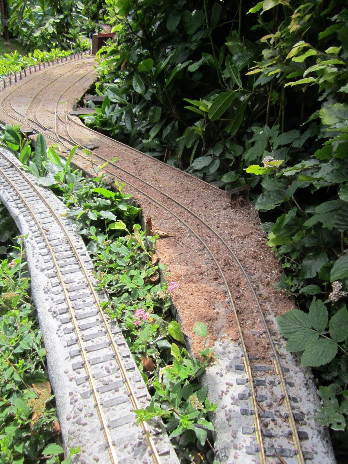
After reconfiguring the track layout at the Copper Mine (see Progress Report 58), the track was badly in need of re-ballasting. After tracking down and acquiring some coarse-grained sand, the copper mine sidings have now been re-ballasted in a similar way to Beeston Market Station yard (see How I ballasted Beeston Market yard).
The mainline running alongside the sidings was also ballasted with a mix of grey tile grout and 5mm alpine grit. You can see one of my resident robins giving it his careful scrutiny.

The approach to the sidings was also ballasted with a mix of local red sand, alpine grit and soil - all held in place with builders' SBR adhesive.
General track maintenance
Inevitably, as with a real railway, the track needs constant attention. The approach to the swing bridge needed the brass tubing for the alignment pins re-soldering and the curve on the track improved with the jim crow (see How I ironed out some kinks in my track) - it was having a tendency to straighten-out.

Most of the point-blades around the layout needed to be cleared of debris to ensure they sat more closely to the stock rails which is a constant battle. The Picaxe controlled remote point switching system was also checked and slight inconsistencies in the connections to the point motors ironed out (see How I constructed a remote control system for operating LGB point motors)

Most of the point-blades around the layout needed to be cleared of debris to ensure they sat more closely to the stock rails which is a constant battle. The Picaxe controlled remote point switching system was also checked and slight inconsistencies in the connections to the point motors ironed out (see How I constructed a remote control system for operating LGB point motors)
Lineside
Beeston Market Coal Yard
A start has been made on the coal yard at Beeston Market Station. The staithes holding the coal have been constructed from stripwood and balsa (see How I made some coal staithes).Eventually, a coal office building will be added together with additional detailing such as weighing scales, sacks, figures and a delivery wagon.
Fencing beside the Copper Mine
This had been on the to-do list for quite a while. Stripwood posts had been in places for some time but I had never got around to adding the wires. As some of the posts had become broken, I decided to replace them all (with 8mm square stripwood), suitably drilled ........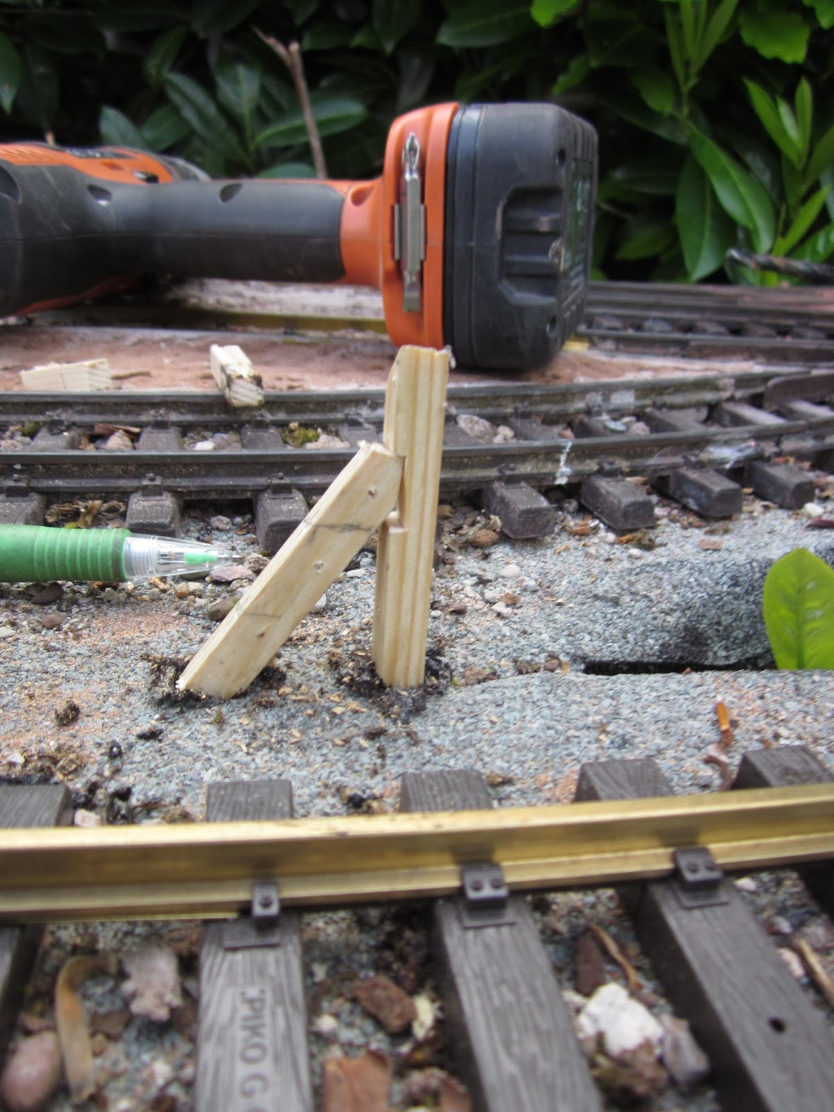
..... to take thin copper wire.

The posts were then given a couple of liberal coats of wood preservative.

Copper Mine plate girder bridge
Three bridges are needed to carry the 32mm feeder line (see Progress Report 59) and so far just one has been constructed. This was made from a couple of 00 scale Wills vari-girder kits (see How I constructed a girder bridge for the mine feeder railway - pending).

There are still two more bridges to construct. One will be another plate girder but the other will be a short wooden trestle.

There are still two more bridges to construct. One will be another plate girder but the other will be a short wooden trestle.
Operating sessions
Despite all this construction work, I have managed to fit in some operating sessions. I have not yet managed to work a complete timetable through, but I have run a couple of freight handling sessions and also been able to run some passenger services and the occasional copper ore train.This video shows extracts from the most complete operating session
While this shows the running of a freight service, one evening when the air was warm and I had an hour or so to spare before settling in the evening.
For me, this is one of the joys of garden railway modelling. I can run full prototypical timetabled sessions or just put a fairly random selection of stock and a loco on the track as the fancy takes me.
Visitation
Finally, I was fortunate enough to host a visit from a fellow garden railway modeller who runs the Deben Valley Light Railway. It seems we have quite a lot in common - we both use 45mm track, our railways depict hypothetical railways in real locations, we both enjoy running goods and passenger services and we both admire the Southwold Railway. One major difference between us is that he greatly enjoys operating with live steam, whereas I am (at present) fully committed to battery electric. Zach brought some of the DVLR stock with him, including one of his live steam locos - an early Merlin 'Little Wonder' loco - River TangSo, for the first time in the Peckforton Light Railway's history, a live steam loco ran on her metals.


It made me realise that my railway was not constructed with live steam running in mind. I have too many gradients and undulations which I hardly notice when running battery locos (or their forerunners, track-powered locos), but which require very careful driving when operating a live steam loco.
I was also delighted to have a former Compton Down loco constructed by the sadly missed Peter Jones running on my railway.

What on earth is there not to like about this hobby?


