Showing posts with label minimum gauge railway. Show all posts

Tuesday, May 14, 2013

How I constructed some Gn15 skips from Smallbroook kits

Why a 15" gauge feeder?

The copper mines which provide the main rationale for the Peckforton Light Railway are served by a 15" gauge railway system. There is a clear reason for this choice of a 'minimum gauge' feeder line for the Peckforton Railway. In my hypothetical history (see A history of the railway), the local landowner and keen engineer, Lord Tollemache, was the main driving force behind the development of the mines and the railway. I've assumed he would have been very familiar with the 15" gauge Eaton Railway which had been constructed a short distance away from Peckforton on the Duke of Westminster's estate by the pioneer of minimum gauge railways, Sir Arthur Heywood. It seems reasonable that Lord Tollemache would have experimented with a minimum gauge railway to both serve his estate and to negotiate the narrow galleries and tunnels of his copper mines.


The location

Having just completed the buildings for the copper mine (See Progress Report 45) I felt the need to construct a short stretch of Gn15 railway to represent the transportation of the ore and spoil from the mines to the crushing shed and the loading chutes. This, of course, would require some rolling stock. I had previously acquired a loco, a tub and a flat wagon through a well known online auction site but needed to source some appropriate looking skips.

 I had considered making my own but eventually decided I needed the time this would take to devote to other projects on the railway. The most appropriate models seemed to be those provided by Smallbrook Studio. Whilst these are designed for use on 0n16.5 railways, Smallbrook suggests they are equally appropriate for Gn15 - which indeed they are!

Construction

 The kit arrives complete with all fixtures and fittings, and a well explained instruction leaflet.

The resin castings inevitably require some tidying to remove flash, this was achieved with a couple of needle files.

 After suitably sized holes (2.5mm and 0.8mm) were drilled in the ends using the marked centres, brass panel pins were inserted and fixed in place with Superglue for the pivots for the skip .....

 ...... and a suitably bent piece of copper wire was inserted to act as the lifting handle.

 Once the glue had set, the excess was snipped off and filed flat on the inside of the skip tub.

 The two pieces of the chassis were then filed and glued together. The lower half of the chassis is weighted with lead shot which has been embedded in the resin - hence its spotty appearance.

Although the instructions suggest applying the paint at this stage, I decided to add the two squares of plasticard which are provided to make the coupling pockets on the chassis sub-base.

I then filed off the pinpoint bearings on the end of the axles for the wheelsets which again are provided in the kit.

The chassis and the skip tub were then given a couple of coats of Plasticote red oxide primer and then the axle mounts were reamed out with a 2mm drill held in a pin-chuck before the wheels and axles were clipped into place. The couplings were assembled and pushed into the pockets ........

......... and then the wagons were suitably weathered and rusted in my time-honoured way (see How I weathered a set of LGB tippler wagons).

 They have now entered service and, although their use on the railway is purely cosmetic; I am not intending to make the 15" gauge line operational; I do have tentative plans for the construction of a Gn15 indoor railway to represent part of Lord Tollemache's estate and copper mine railway which I can easily imagine wending its way along the Peckforton Ridge. It seems that, once bitten by the railway modelling bug, there's no known cure!

Thursday, December 27, 2012

Bickerton Copper Mine

A brief history of Bickerton Copper Mine

It is thought that copper has been mined at Bickerton and Gallantry Bank since the Bronze Age and by the Romans, but the earliest documented reference to mining in the area is in a report written by J D Brandshagen in 1697 for Sir Philip Egerton.  The sandstone outcrop at Peckforton forms part of the same geology as that of Alderley Edge, where there is also evidence of copper mining (See Copper Mining at Alderley Edge).
Alderley Edge Copper Mine: Source http://www.derbyscc.org.uk/caving/caving_image/JK_trip_20060507_21_resize.jpg
The seams of copper were worked intermittently until the 1860s though there was an optimistic survey carried out in 1906 in a bid to raise capital for a more extensive mining venture.
Today, there is very little evidence of the copper mining industry at Bickerton and Peckforton. It is possible to squirm into an abandoned adit in the hillside above the Bickerton Poacher pub, but the five main shafts to the deeper copper seam have long since been sealed. The remains of the chimney for the boiler serving the pumping engine above the main Engine Shaft can be seen from the A534 road.
The remains of the chimney beside the sealed Engine Shaft (Source: http://upload.wikimedia.org/wikipedia/commons/7/70/Copper_mine_chimney_-_geograph.org.uk_-_713124.jpg)
I have been unable to find any drawings or photos of the copper mine when it was operational, the earliest I've been able to discover shows it in a derelict state taken at the beginning of the 20th century:
Bickerton Cooper Mine circa 1904 (Source: http://www.sandstonetrail.com/wp-content/uploads/Coppermine.jpg)

 The mines

 Although Shaft No. 5 and the Pit were shown in an 1890 survey of the mine workings (Edwards, 1890), only the Engine Shaft and Shafts 1, 2, 3 and 4 are shown in the 1906 survey (Spargo & Thomas, 1906) suggesting these were the only workable shafts at that time. This drawing shows the approximate position and extent of the workings based on these two surveys (click on the image to enlarge).
Bickerton Copper Mine (Based on Carlon (1981) Fig vii)
The Engine Shaft was the deepest, at 156 feet, No. 1 shaft was around 60 feet deep, No. 2 shaft was 35 feet deep, No. 3 shaft was around 110-120 feet deep, shaft No. 4 was somewhere between 117 and 135 deep while shaft no. 5 was 65-70 feet deep. As the the ore zone was inclined at an angle of approximately 80 degrees to the vertical, various levels and stopes needed to be worked from the shafts to access the ore. Shafts No. 4 and 5 were the oldest, and were worked until the beginning of the 19th century. Only Shaft 3 continued working after the mid 1800s. The pit between shafts 4 and 5 was later used as a well.

It is assumed that the mine shafts at Bickerton were relatively dry as the pumping engine over the Engine Shaft was a modest affair. Over the years, advice had been sought from Cornish mining engineers and so it is highly likely that the mining practices at Bickerton would have been heavily influenced by those carried out in Cornwall.
The type of pumping engine house possibly used at Bickerton (Source: http://farm5.static.flickr.com/4079/4798065476_e74ec2c1ee.jpg)
As the main shaft used for the extraction of ore was Shaft No.3 it must be assumed there was some sort of winding engine situated nearby, though this is not documented in any of the sources consulted.
Steam powered winding engine used in copper mine (Source http://s0.geograph.org.uk/geophotos/02/32/38/2323827_775bb0fa.jpg)
Through the 18th and 19th centuries various schemes were put into effect to develop the mine but by the turn of the 19th century, the mine had been left unworked for around 35 years. Edmund Spargo's survey of 1906 concluded that by widening and deepening the main shafts the mine could easily be expected to yield around 18000 tons of copper which would net a profit of around £1.1m (equivalent to around £115m today)! The Bickerton Copper Mines Syndicate Ltd. leased the mines for three years in 1907 but seem to have carried out very little work and was dissolved in 1911. In 1917, UK Minerals Development took out a three year lease of the mine but again very little work took place. During the 1920s, three local men worked No. 3 shaft intermittently using a bucket, rope and hand winch and unearthed some rich pieces of bright blue crystalline azurite.
Azurite and malachite (Source: http://upload.wikimedia.org/wikipedia/commons/9/97/Azurite-Malachite-59275.jpg)
By the 1930s the mines gradually fell into decay until the shafts were filled and sealed in the 1960s and what remained of the mine buildings were demolished in a road widening scheme in 1977.

 The minerals

There were two veins of copper-bearing rock in the mine at Bickerton which varied in width from eight inches to five feet, with an average of 2½ feet. There was also thought to be cobalt, lead and silver deposits in the seams. In 1802 a sample of ore from Bickerton was sent to the Mineralogical Society for analysis which pronounced there was 9% copper in the sample in the form of copper sulphide and copper carbonate. However, another analysis in 1806 found the ore varied in quality from 0% to 2½%, whereas another in 1862 found there was between 19¼% and 25% of copper and 18 ounces of silver per ton of ore.

The minerals present in the ore were malachite and principally azurite, though there were also traces of chrysocolla, melaconite, bornite and covellite. These were deposited in an almost vertical fissure of white sandstone, similar to that found at Alderley Edge, Clive, Pim Hill, Whixall and Eardiston.
Mineralised sandstone from Alderley Edge (Source: Minerals UK)

 The copper mining process

Until the middle of the 19th century, copper was extracted and processed mainly by hand, but thereafter mechanisation played an increasing role. By the early 1930s, when my model is set, pneumatic and hydraulic mining equipment would have been used, though this would also have been supplemented by hand tools and the use of explosives. As the shafts and galleries were very narrow, it seems reasonable that the narrowest gauge of railway would have been used to transport the ore and spoil beneath the ground. Railway tracks were found in the mines at Alderley Edge - though these are associated with later restoration work.
Copper Mines at Alderley Edge (Source: http://www.mine-explorer.co.uk/photo_cache/mines/Alderley-edge_2547/Alderley-edge_22468.jpg)
By contrast, in the Parys Mine in Anglesey there were no underground railways in the copper mine owing to the corrosive effects of contaminated water on the equipment (see Parys Underground Group - Railways). As we have seen above, the mines at Alderley Edge and Bickerton were relatively dry and it is more likely they would have used underground railway trucks to transport the ore and spoil if the mines had been further developed.
Tub from the Saint Veran Copper Mine in France (Source http://www.aditnow.co.uk/photo/Personal-Album-1-Image-067)
Once extracted from the mine the ore was crushed and then ground before the copper-bearing minerals were further extracted using an oil flotation process where the impurities rose to the surface and were skimmed off. The ore would then be smelted and refined.
Copper Processing (Source: www.bgs.ac.uk/downloads/start.cfm?id=1410)
 Once the ore had been removed from the mine and crushed, any rock which held more than 5% of copper could be sent directly to the smelters while any below that could be treated using the wet acid process which would produce copper sulphate (used as a crop spray).

The (fictional) history of the Peckforton Light Railway

To provide my 16mm scale garden railway with a realistic context, I have made some hypothetical propositions and just a few flights of fancy. However, where possible, these have been based on facts and reflect what might have happened, given the certain favourable conditions. My fictional inventions are shown in italics, the rest is factual.

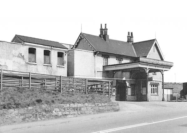
In my imagined history (see A History of the Railway), the local landowner, Lord Tollemache, decided to invest in the copper mines following the optimistic report produced in 1906 by Spargo and Thomas. As a consequence built a three foot gauge railway to transport the mined ore and spoil to the mainline Crewe to Chester railway via the former Beeston & Tarporley Station. Bentley Tollemache succeeded his father, Wilbraham, as the 3rd Baron Tollemache in 1904 and as such became the owner of the Peckforton Estate which included Peckforton Castle. Peckforton Castle was built in the middle of the nineteenth century by his grandfather, John Tollemache (see History of Peckforton Castle). It was designed in the Gothic style by the architect Anthony Salvin and was described in 1858 by Sir George Gilbert Scott, the architect of St Pancras Station, as "the largest and most carefully and learnedly executed Gothic mansion of the present."
Peckforton Castle shortly after completion in 1851 (Source: http://www.dicamillocompanion.com/images/Houses/database/Peckforton_Castle.jpg)
Bentley Tollemache was actually a keen amateur engineer and I like to imagine that, as a consequence, he would have been very enthusiastic about constructing a narrow gauge railway to serve his pet project, the mining of copper on the edge of his estate. I also hypothesise that he would have constructed a 15" minimum gauge railway to handle freight within his estate, inspired by that constructed by his near neighbour, the Duke of Westminster at Eaton Hall (see Eaton Railway) and influenced by the work of Sir Arthur Heywood (see Historical Background to Minimum Gauge Railways)
Source: http://www.eatonestate.co.uk/NR/rdonlyres/914E2056-B26C-4216-9DD2-3E2E28C8E274/8142/Katie.jpg
I am assuming that as the ores were relatively copper-rich at Bickerton (if Spargo & Thomas are to be believed), once extracted from the mine they would then crushed before being loaded into wagons for transhipment to be processed and smelted elsewhere - maybe near the sister mines at Alderley Edge. I am also assuming that Lord Tollemache was a canny businessman and that he would have identified a ready market for the non-copper-bearing spoil. The sea defences along the Dee Estuary were being reinforced during the period in which my model is set and hence there would have been a call for crushed rock and rubble from a range of sources.
The Dee Estuary (Source: http://www.gutenberg.org/files/29787/29787-h/images/p033.jpg)
 My model of the mine assumes that more than one shaft would have been enlarged to allow for the mechanical extraction of the copper ores. Furthermore, additional shafts will have been sunk along the ore line to gain access to other rich deposits of copper-bearing ores. These shafts would have been interlinked at the surface by a 15" minimum gauge railway using internal combustion powered locomotives. Rock from the workings would be transported to the crushing and sorting machinery housed in sheds adjacent to the pumping engine and old mine workings beside the Engine Shaft. The pumping engine would have been updated, but remained steam driven, whereas the crushing, sorting and conveyor mechanisms would have been powered by diesel engines.
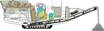
Ore crusher (Source: http://www.bricscrushingplant.com/images/solutions/gen/36.jpg)
 Although the image above shows a modern mobile ore crusher, the technology has not changed radically over the years and a similar, albeit stationary, system of crushing would have been in use in the 1930s. The ore is loaded into a hopper on the left and is fed into the crusher mechanism, which crushes the ore between fixed and movable jaws. The crushed ore is then conveyed to a loading hopper (see How I constructed a wooden loading hopper).

By 1932, when my model is set, I'm assuming that the viably workable seams were becoming exhausted and so there was proportionately more spoil being extracted than copper ore. As a consequence, there was less money available for carrying out repairs and the railway and the works were beginning to fall into decay. However, the tourist potential of the area was becoming more lucrative as the healing powers of the mineral waters in the Peckforton Hills were being exploited and the largely unspoilt scenery around Beeston and Peckforton Castles proved attractive for Bank Holiday visitors from Manchester and Birmingham.

Bibliography

  • C.J. Carlon. (1981) British Mining No.16:- The Gallantry Bank Copper Mine, Bickerton, Cheshire
  • H. Dewey. T. Eastwood. (1921) MGS Special Reports, Vol. XXX: Copper ores of the Midlands

Monday, November 19, 2012

Progress Report 43

This year I have had fewer opportunities than in previous years to run trains on the railway. Firstly, the weather has been very changeable which has meant that there have been relatively few days when an unbroken spell of decent weather could be guaranteed. On a couple of occasions, I had spent an hour or so setting up the railway, only to have to gather everything together and dash back indoors as a shower of heavy rain blew up. Secondly, I have spent several days during the summer period visiting full-scale narrow gauge railways for a new blog which I have set-up (see Narrow Gauge Railways UK). Mostly, these visits seem to have coincided with a spell of decent weather which I could have used for running the railway.
Orenstein & Koppel 0-4-0 locos Utrillas and Montalban at the West Lancashire Light Railway

 Thirdly, I have spent quite a bit of the summer, doing running repairs, constructing signals, making a set of buildings for the copper mine and experimenting with radio control (see below).


Running repairs

These have mostly centred on improving the running of stock which had wheels which were incompatible with LGB pointwork (see How I made IP Engineering wheels compatible with LGB pointwork). There would appear to be very little conformity over back-to-back measurements and flange depth of wheels across manufacturers when it comes to 45mm gauge. As a consequence, when products from different suppliers are brought together, there are often problems with smooth running through pointwork. Whilst I have sometimes re-wheeled stock to overcome these difficulties, there are occasions when this is not possible or desirable as, for example, when journals or axle stubs wheel sizes are non-standard. I have developed a rough-and-ready method of beefing-up finer scale wheels to improve their running characteristics through the coarser scale frogs of LGB pointwork.

Another issue associated with LGB pointwork which I have uncovered over the seven years I've been running my railway has been a steady and consistent breakdown in electrical continuity between the running rails, point-blades and lead-rails before and after the frogs. I could have removed every point and soldered invisible connections beneath the rails and sleepers, but when I have done this in the past it has caused more problems than it solved. Consequently, I opted for an in-situ solution of soldering jumper wires from the stock rails to the switch rails.
For more information see - How I repaired LGB pointwork


Constructing signals

As I try to run my railway according to light railway prototypical practices (which of course were often quite idiosyncratic), I decided that with up to three trains in steam at any one time, it was about time I supplied the line with signalling.

Using the signalling diagrams which were provided by a fellow modeller who also happens to be a Railtrack signalman (see Progress Report 36) ........


......... I figured that even the most minimal approach to signalling the railway would require 20 signals (around 4 per station). I explored various kit-built options but decided that the cost would be prohibitive. I had no option but to construct my own signals.

Although the signals were  of the same basic design as I wanted to batch-produce them, there were two alternatives in terms of the types of base. One type had a plate base for mounting on hard surfaces, while the other had a concrete base, for mounting in soft surfaces .......

All the signals are equipped with flickering LED lamps..........

 ....... which are shuttered at the rear.

At present, the signals are operated individually but eventually I hope to have them operated through linkages to a ground frame at each station, as per prototype.


For details of construction see Garden Rail edition 224 (April 2013).

 Mine buildings

Up until now, the sidings for the copper mine have had only a backdrop of the laurel hedge.

Ever since the extension to Beeston Market and the copper mine was constructed (see How I built the extension), I have been planning to add some buildings and loading hoppers.

At this stage, construction is well under way - with a variety of techniques being deployed.
The crusher shed and manager's office
The workshop

 The buildings are still very much work-in-progress with a lot more tidying-up and detailing needed. Once completed, the buildings will include a Gn15 feeder line from the mine workings together with loading hoppers and conveyors. See How I constructed the Mine Buildings)


Radio control

I have been broadening my experiments with battery operation and radio control, following the construction of my first battery powered radio controlled vehicle, a double-ended railbus (see How I constructed a railbus from two Andel coach kits).

A chance-find on eBay resulted in the purchase of a couple of cheap 2.4GHz radio transmitters designed to be used with low-cost helicopters.

I discovered that the transmitters worked with cheap FlySky receivers and so, after setting-up a test-rig, I explored the potential of this cost-effective approach to radio control.

As you can see from the video, with the modest outlay I'm figuring it's worth producing a small fleet of battery-operated locos to run alongside and maybe eventually replace the track powered locos. I have a couple of spare ToyTrain loco blocks which can be pressed into service and one day I will get around to converting my LGB 0-6-2 U-Class Zillertalbahn loco into a representation of the Southwold Railway loco No. 4 Wenhaston.

Sunday, July 03, 2011

A short history of the Peckforton Railway and its locality (real and fictional)

Key: Real historical events are in plain text, added fictional events are in italics.

Before the coming of the railway

In 1904, at the age of 21, Bentley Tollemache succeeded his father, Wilbraham, as the 3rd Baron Tollemache and owner of Peckforton Castle.

 His father had installed electric lighting and central heating into the castle and Bentley turned his attention to the estate. Like his father, he was very forward thinking and had developed a keen interest in engineering as well as being an enthusiastic croquet player, publishing a book on the subject in 1914.
Source: http://www.croquetworld.com/Game/tollemache.asp

The copper mines at Bickerton had been worked from the 1600s and had yielded sufficient quantities of ore to keep small numbers of men productively engaged from time to time. A comprehensive geological survey was conducted in 1906 which indicated there were substantial reserves of ore yet to be mined. Indeed the report suggested that the Bickerton mines could become the most productive in the British Isles - though how much of this was a marketing ploy is difficult to determine.
 Lord Bentley Tollemache would have been very familiar with the 15 inch gauge miniature railway built for his near neighbour, the Duke of Westminster, at Eaton Hall in 1896.


The Railway
 Being very interested in engineering, Lord Tollemache immediately saw the potential of exploiting the mineral wealth beneath his feet and so immediately bought up the rights to the mine and set about drawing up plans for the construction of a railway to transport the copper ore and most of the spoil. Under the Light Railways Act (1896), Lord Tollemache decided to build a three foot gauge railway just under seven miles in length from Beeston Castle & Tarporley Station on the Crewe to Chester mainline to the hamlet of Bickerton.
 

There were three intermediate stations - one serving the village of Beeston and Beeston Castle, another roughly half way along the line at Peckforton and the third in the village of Bulkeley. A spur between Bulkeley and Bickerton served the copper mines. 

There were no major engineering works, though the route required cuttings and embankments near Peckforton and Bulkeley. Whilst the railway crossed six minor roads via unmanned level crossings, it was decided that where the line crossed the main road from Whitchurch to Wrexham (the A534) between Bulkeley and Bickerton and on the copper mine spur, the road would be carried across the railway on overbridges constructed from the local sandstone.

The railway was opened for traffic in 1908, with initially two 0-4-0 locomotives (a Hunslet and a Pecket) and a 2-4-0 Barclay. A rake of three coaches was provided by the Pickering company, together with four closed vans, twenty open wagons, four cattle wagons and two guards vans. A diesel mechanical was provided for the mine traffic in 1924 and in 1929, a Manning Wardle 0-6-2 locomotive was added to the roster, following the closure of the Southwold Railway.

Over the years, further good stock was added, mostly bought secondhand from other railways. Additional rolling stock to cater for timber traffic was added in 1924 after much of the Peckforton estate was forested in 1922.

The railway company, under the chairmanship of Lord Tollemache, quickly realised the potential for tourist traffic with visitors taking trips to Beeston Castle and Peckforton Castle, or to take the mineral waters from the wells in the Peckforton Hills. In 1910 a hotel and health spa was built near Peckforton to allow visitors to sample the local mineral waters
Source: http://www.peckforton.co.uk/_/bottles.html
 Whilst the copper mine and the railway were never a money spinner, the railway continued a successful existence, thanks largely to the patronage of Lord Tollemache, until the end of the second World War when, in 1945, it ran its last train and the track and rolling stock were scrapped.


Little remains of the line today. The overbridges were demolished when A534 was widened in the 1960s and the narrow gauge station and goods yard were sold off when the mainline station at Beeston was closed in 1966. The site now houses a reclamation yard.