Now we are entering the winter season, there are fewer opportunities to run trains, but supposedly more opportunities for finishing off construction projects. So far, it has turned out to be more difficult than expected to find time for construction and so progress has been limited. However, there are several projects now on the agenda which I can report on.

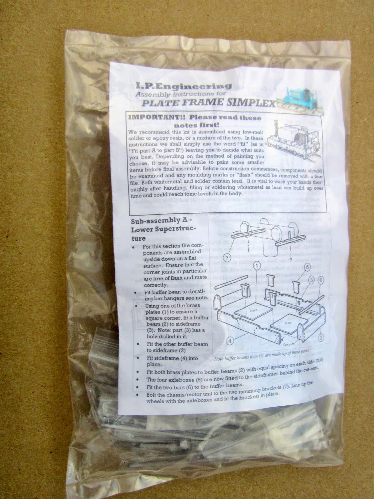
My thinking was that by having a short stretch of 32mm track, I would have some stock which I could run when I visit other people's garden railways. I am also considering building a simple shuttle control system using a Picaxe micro controller. In the meantime, I now have an IP Engineering Simplex locomotive kit sitting in my 'pending' project box awaiting its turn on the to do list.

The van itself has been constructed fairly crudely from plywood and mounted on an LGB chassis. This makes it quite heavy when compared to similar stock. The mouldings are mot particularly crisp and the paintwork is far from smooth. I think it will need some remedial work after being rubbed down in preparation for a repaint.
 Also, it is taller than the existing rolling stock and I may consider
lowering it on its chassis somehow. This is not a high priority on the
todo list and so may languish on the shelves for a while before I decide
to deal with it.
Also, it is taller than the existing rolling stock and I may consider
lowering it on its chassis somehow. This is not a high priority on the
todo list and so may languish on the shelves for a while before I decide
to deal with it.

Also included in the order were some works plates. Two sets of Manning Wardle plates for the former Southwold and Davington LR locos and a set of Sharp Stewart plates for Tarporley.
I still need to complete the roofs, windows, lights, underframe detailing and
balconies for these two coaches but, by comparison with the work needed
to modify the bodywork, progress should now be a lot swifter.
After reading through some postings on the 16mm NGM forum, I have decided to experiment with printing the stained glass window detailing for the opening lights on to self adhesive acrylic sheet from Crafty Computer Papers.
I decided to invest in a Tx21 so that when I have visitors there's another controller so we can run trains independently. This was certainly an asset when my Australian friend visited in October (see Progress Report 55).

I was pleasantly surprised at how easy it was to construct the transmitter. The main circuit board was included as a completed unit and all that was required was to drill holes in the case, mount the switches and potentiometer and then solder a few wires from the transmitter chip to the various switches. A few resistors needed to be included in some of the connections but these were relatively easy to solder into place. I'd say the drilling was the most difficult aspect of the build - ensuring the holes were in the right places and correct size.

Over the past couple of years, I have accumulated a range of Deltang receiver/controllers as and when they became available. Some of the early receiver/ESCs were rated only at 1amp which proved to be quite adequate for the LGB motor blocks I was using - but now that the Rx65 3amp receiver/controller has become available, I have decided to standardise.

My most recent loco, the Manning Wardle 0-6-0 has been equipped with one of these receivers and I have been very impressed with its performance. (see Manning Wardle load test video). It seems to be far more responsive and consistent in its smooth running, Whether the Piko 0-6-0 mechanism is responsible or whether the output from the receiver is the major contributory factor remains to be seen - but I will keep readers posted as to progress once the receivers have been installed.

Previously, I have been accumulating the necessary electronic bits and pieces needed to construct my own sound card using a Picaxe chip and a small amplifier. I am intending to follow the guidance given by my Ozzie visitor on his railway's website - http://www.trainweb.org/SaTR/Picaxe%20tutes.htm.

I have also invested in a small sound recording chip similar to those used in greetings cards.

I am hoping that this will prove small enough to fit inside the Lollypop railcar (see How I Constructed an IP Engineering Railcar)
I still have four locomotives without sound (two steam and two internal combustion) and so, during the coming Spring I intend to construct my own sound systems using a combination of these components. Watch this space for more details.


I am hoping for some light snowfall before the end of the winter. Probably because of the hassle associated with using track power, I have, up to now, never taken photos of trains when snow was on the ground. Maybe a light dusting of snow will provide some photo opportunities.

Acquisitions
Christmas has come and gone and left me with a couple of additions to the stocklist.IP Engineering Simplex kit
I have been considering for a while making the feeder from the copper mine to the crushers and loading hopper into a 32mm (2') narrow gauge line (see Progress Report 45). At present it is 16.5mm gauge supposedly representing a 15" gauge railway (but nearer to 13") (see How I constructed some Gn15 skips) and as such it will only ever be cosmetic.My thinking was that by having a short stretch of 32mm track, I would have some stock which I could run when I visit other people's garden railways. I am also considering building a simple shuttle control system using a Picaxe micro controller. In the meantime, I now have an IP Engineering Simplex locomotive kit sitting in my 'pending' project box awaiting its turn on the to do list.
Guards' / baggage van
I saw this on a well known online auction website and considered that the price was sufficiently attractive for it to become an addition to the line. At present, I do not have a dedicated guards' van which could be included in passenger trains and thought this might add more operational interest.The van itself has been constructed fairly crudely from plywood and mounted on an LGB chassis. This makes it quite heavy when compared to similar stock. The mouldings are mot particularly crisp and the paintwork is far from smooth. I think it will need some remedial work after being rubbed down in preparation for a repaint.
Nameplates
I've recently taken delivery of another two etched nameplates from Narrow Planet - my preferred supplier. The former Southwold Railway Sharp Stewart 2-4-2T (see How I constructed a Sharp Stewart 2-4-2T) will become Tarporley and the most recently completed former Davington Light Railway Manning Wardle 0-6-0 will become Harthill (see How I constructed a Manning wardle 0-6-0T). I am following the tradition set by the Southwold Railway of naming locomotives after villages and towns served by the railway.Also included in the order were some works plates. Two sets of Manning Wardle plates for the former Southwold and Davington LR locos and a set of Sharp Stewart plates for Tarporley.
Jackson Sharp coach bashes
I am making slow but steady progress with these builds. One Open coach has been more or less completed, apart from interior detailing, while the modifications to the underframes and body shells for the remaining Open and the Brake are largely done. |
| Open Coach based loosely on the Leek & Manifold coaches |
 |
| Progress so far on the Brake End L&M inspired coach |
Deltang radio control equipment upgrades
Since the last update I have constructed a new Tx21 transmitter from a kit and taken delivery of two Rx65b receiver/controllers from Deltang.I decided to invest in a Tx21 so that when I have visitors there's another controller so we can run trains independently. This was certainly an asset when my Australian friend visited in October (see Progress Report 55).
I was pleasantly surprised at how easy it was to construct the transmitter. The main circuit board was included as a completed unit and all that was required was to drill holes in the case, mount the switches and potentiometer and then solder a few wires from the transmitter chip to the various switches. A few resistors needed to be included in some of the connections but these were relatively easy to solder into place. I'd say the drilling was the most difficult aspect of the build - ensuring the holes were in the right places and correct size.
Over the past couple of years, I have accumulated a range of Deltang receiver/controllers as and when they became available. Some of the early receiver/ESCs were rated only at 1amp which proved to be quite adequate for the LGB motor blocks I was using - but now that the Rx65 3amp receiver/controller has become available, I have decided to standardise.
My most recent loco, the Manning Wardle 0-6-0 has been equipped with one of these receivers and I have been very impressed with its performance. (see Manning Wardle load test video). It seems to be far more responsive and consistent in its smooth running, Whether the Piko 0-6-0 mechanism is responsible or whether the output from the receiver is the major contributory factor remains to be seen - but I will keep readers posted as to progress once the receivers have been installed.
Sound cards
My Australian friend, Greg, came bearing gifts, among which included a few 20 second sound recording chips.Previously, I have been accumulating the necessary electronic bits and pieces needed to construct my own sound card using a Picaxe chip and a small amplifier. I am intending to follow the guidance given by my Ozzie visitor on his railway's website - http://www.trainweb.org/SaTR/Picaxe%20tutes.htm.
I have also invested in a small sound recording chip similar to those used in greetings cards.
I am hoping that this will prove small enough to fit inside the Lollypop railcar (see How I Constructed an IP Engineering Railcar)
I still have four locomotives without sound (two steam and two internal combustion) and so, during the coming Spring I intend to construct my own sound systems using a combination of these components. Watch this space for more details.
Track cleaning
One of the great joys I have now is being able to run trains with the minimum of track cleaning and maintenance, compared with that required for operating track-powered locomotives. Recently, after a few weeks with no trains, I decided to have a short running session and was pleasantly surprised at how quickly I could have something up and running compared with the days when I ran only track-powered locos.Then
Track cleaning preceding a running session used to take a minimum of an hour and on average would take two hours. Once the track had been cleared of debris and encroaching vegetation, I would previously have had to scrub the rail surfaces with an abrasive block and then check for electrical continuity by running a light loco around the track. (see Cleaning the track) If I was lucky, it would manage an entire circuit without stalling. Often, however, there would be a dead spot on the track. This might be caused by the breakdown of the bonding between two lengths of rail (see How I bonded the rails) or could be because the bonding between the rails in the pointwork had deteriorated (see How I improved the electrical continuity of pointwork).Now
My track cleaning is now a lot more efficient. Clearly, I have to remove debris and overhanging vegetation from the track as before, but that's it. To keep the trackbed reasonably clear, I have taken to sweeping it with a stiff handbrush, which not only removes leaves and branches, it clears away excess moss and encroachment from Mind Your Own Business.I am hoping for some light snowfall before the end of the winter. Probably because of the hassle associated with using track power, I have, up to now, never taken photos of trains when snow was on the ground. Maybe a light dusting of snow will provide some photo opportunities.


