
Introduction
I've always fancied having a de Winton vertical boilered loco running on the PLR. I do have a Regner Chaloner, but it's over-scale and also being live steam only makes an appearance once in a while.
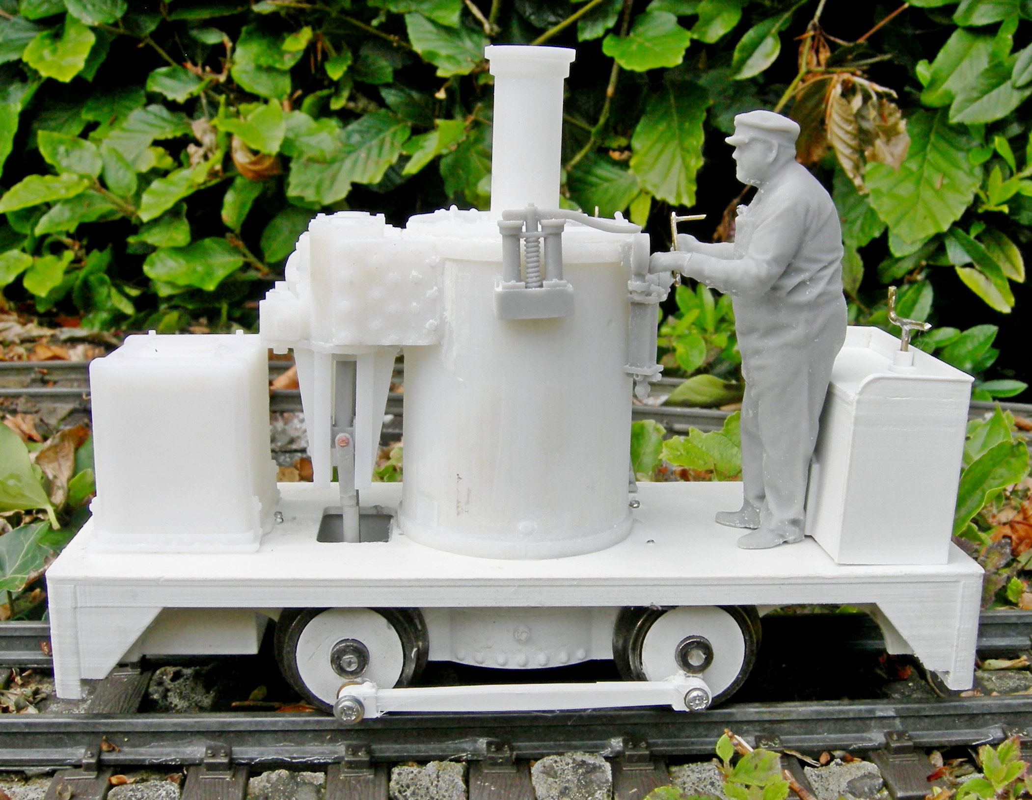
When a fellow modeller announced on the GScaleCentral.net forum that he had designed and 3D printed a 32mm gauge version, I downloaded it from Thingiverse and designed a 45mm chassis for it.


With all the parts printed-out, I started construction. The model went together reasonably well, though some of the parts needed some adjustment to make them fit.


The beauty of 3D printing, for me, is the ease with which parts can be redesigned. And so it was, I made various tweaks to the parts, and set about the printing and assembly of Version 2.
Construction of the final version
As with all my loco builds, I started with the running plate.

This was given a couple of coats of grey primer, followed by a couple of coats of satin black from Halford's rattle cans.
Sheets of lead flashing were inserted into the cavities I had deliberately created for the purpose in the buffer beams; held in place with a few squirts of superglue.


The boiler was primed and sprayed with Halfords light green paint (unfortunately, Halfords seem to no longer produce Rover Brooklands Green - my default loco livery for the past twenty years). The band at the base of the boiler was picked-out in black acrylics.

The top of the boiler was glued to the cap, ......

..... making sure it was centred, and the hinge was parallel with the straight section of the boiler cap.

This sub-assembly was then given a couple of coats of primer and a couple of coats of satin black.


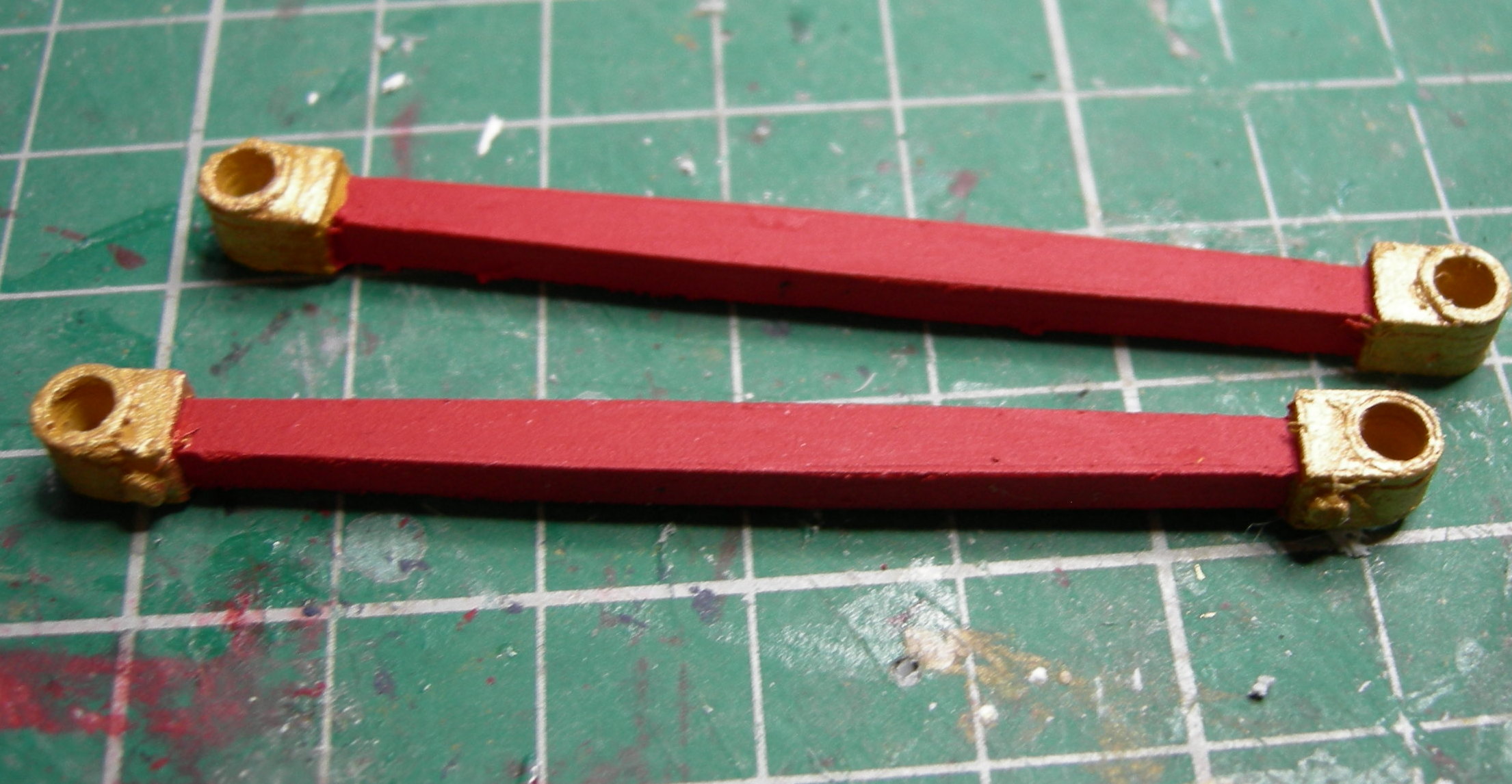
..... were then united with the slide bars, ......
.... using a couple of 3.5mm drill bits in the holes for the piston rods to ensure the two parts were perfectly aligned.


.... and the sub-assembly was given a couple of coats of primer and satin black. The rod controlling the reversing mechanism was picked out in red acrylics.

The boiler top was then loosely fitted to the top of the boiler to assist with the alignment of the cylinder blocks, which were glued into place making sure the slide rods were vertical.

The boiler cap was then removed to ensure it didn't become accidentally glued to the top of the boiler.

The boiler was then glued to the running plate - ensuring the cylinders were perfectly aligned with the longitudinal central axis of the running plate.
NOTE: I have added lugs on the base of the boiler in the online download version, to ensure perfect alignment.

Next, the tank .....

..... and bunker were then primed and painted with Halford's light green paint.


The straps and brackets on the tank were picked out in black acrylics, and the seat of the bunker was painted to resemble wood.
The bunker was glued into place on the running plate, but before the tank was glued on, two 33mm long x 1.5mm diameter brass rods were loosely inserted into the brackets on the base of the tank.

The other ends of the rods were then inserted into the holes at the base of the cylinders before the tank was glued to the running plate
NOTE: I should have chemically blackened the rods before fitting them.


The loco was already beginning to take shape. The next task was to turn attention to the mechanism and electrics before adding the finer (more vulnerable) details.
A GA25-370 (282RPM) 12v gearmotor was acquired from AliExpress .....

I have, in the past used Polulo gearmotors of the same specification (1:40 ratio) but the AliExpress motors are much cheaper and, as far as I can judge, just as effective.
0.8M 15 tooth brass bevel gears of 3mm bore (for the axles) and 4mm bore (for the motor shaft) were acquired from the same source: ....

.... as were 3mm (3x5x2.1-7x0.6mm) top-hat bearings (though, as yet, I've not used these on this particular model). I'll include parts to enable these to be used in the download.

The motor was attached to the mounting plate with two M3 screws.


.... and two 3mm bore bevel gears mounted on a length of 3mm brass rod to act as a lay-shaft. Once it had been tested, the assembly was dismantled and painted satin black before being reassembled and fixed in place beneath the boiler using self-tapping screws in the holes provided.
NOTE: 4mm gears and rod could be used, dependent on the type of bevel gears you have to hand.

NOTE: I filed a couple of flats beneath the bevel gears on the layshaft to give the grub screws more positive purchase, as I found they had a tendency to slip.
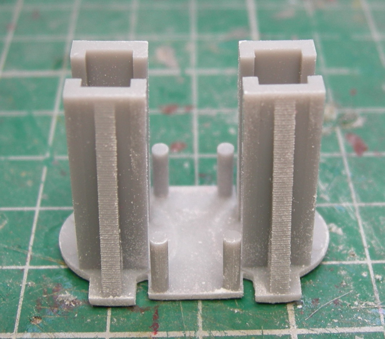
The motion and eccentrics were assembled, using a 3mm diameter drill bit to align the two parts of the eccentric.

The piston rods and cross-heads were connected to the crank rods with brass panel pins, snipped off and held in place with a dab of superglue applied with the tip of a cocktail stick - ensuring no glue infiltrated the pivot. The sub-assemblies were then painted by hand with acrylics to ensure that paint wasn't accidentally applied to the bearing surfaces.

The valve rods were also painted in the same way.

The wheel bearing blocks were spray-painted with Halford's primer and satin black.

I used Bachmann 24.5mm metal wheelsets as I happened to have them to hand - though IP Engineering 24mm wheelsets could be used as an alternative. However, these are mounted on 1/8" axles which will require the 3mm bores of the bevel gears to be opened out slightly (by 0.175mm) unless you can source compatible 1/8" bore bevel gears.
One wheel was removed from the axle and the bearing-blocks, eccentrics and valve rod assembly was slotted on.
NOTE: I have provided two types of valve rods in the download: one which slots on to the axles as shown and another shorter version which floats freely above it to give more leeway in aligning the crossheads with the slide rods. In the end I opted for the floating version.

Once the gauge and back-to-back measurements of the wheels had been checked, the protruding ends of the axles were removed with a slitting disk in my mini-drill, and the bearing-blocks slotted into place in the chassis.
NOTE: A fair bit of fiddling, poking and wiggling was required to ensure the piston rods slotted into the cylinders. Also, I found the paint layers provided a good interference-fit for the bearing blocks in their recesses and so I did not need to glue them into place - making their removal for future maintenance a lot easier. It also allows the axles and wheels and axles to be removed when the wiring is attached (see below).


The wheels were then mounted into the chassis.

Once everything was tested by attaching a 9v battery to the motor, the wheels and axles were removed to allow the wiring-up to take place.
A sub miniature SPDT switch and 2.5mm DC socket were mounted on the running plate and wired-up.

Three 14500 (AA sized) li-ion cells were connected to a BMS protection board and a JST balance charge socket, and then squeezed into the water-tank, which I've enlarged slightly from the actual dimensions to accommodate them.
NOTE: I've provided two versions of the tank in the download - the original to-scale version and the enlarged version to take the batteries.

The baseplate for the water tank.......

..... was then painted satin black and was slotted and screwed into place using the tab and a self-tapping screw.

NOTE: Once the receiver had been tested and shrouded in heat-shrink sleeve, it was slotted in beside the motor and the rest of the space filled with strips of lead flashing to add weight centrally for adhesion - I like plenty of ballast in my locos.

A MyLocoSound universal steam soundcard was slotted in diagonally using the slots I had provided into the bunker and wired into the rest of the wiring and a miniature speaker

As can be seen, I've included holes and moulded clips below the running-plate and chassis to keep the wiring hidden and tidy, though the application of black acrylics to some of the wires might be needed in places.

The wiring for all my locos follows the same pattern

A toolbox was added to the running plate to hide the wiring for the switch and charge socket. At present, this is just loosely fitted but I intend to secure it in place with the judicious use of a blob of BlueTak.


The wheel inserts were painted .....

The wheel inserts were glued on to the Bachmann wheels with superglue, making sure they were quartered to be in line with each other. A 1.5mm hole was then drilled through the metal of the wheel beneath each of the crank-pin holes, so self-tapping screws could serve the double purpose of acting as crank pins and holding the wheel inserts in place.

Once all the electrics had been tested, the finer details were painted .......

and added; as were the reverser.......

..... and regulator with associated pipework.

The handbrake was fashioned from a couple of pieces of brass rod, soldered together.

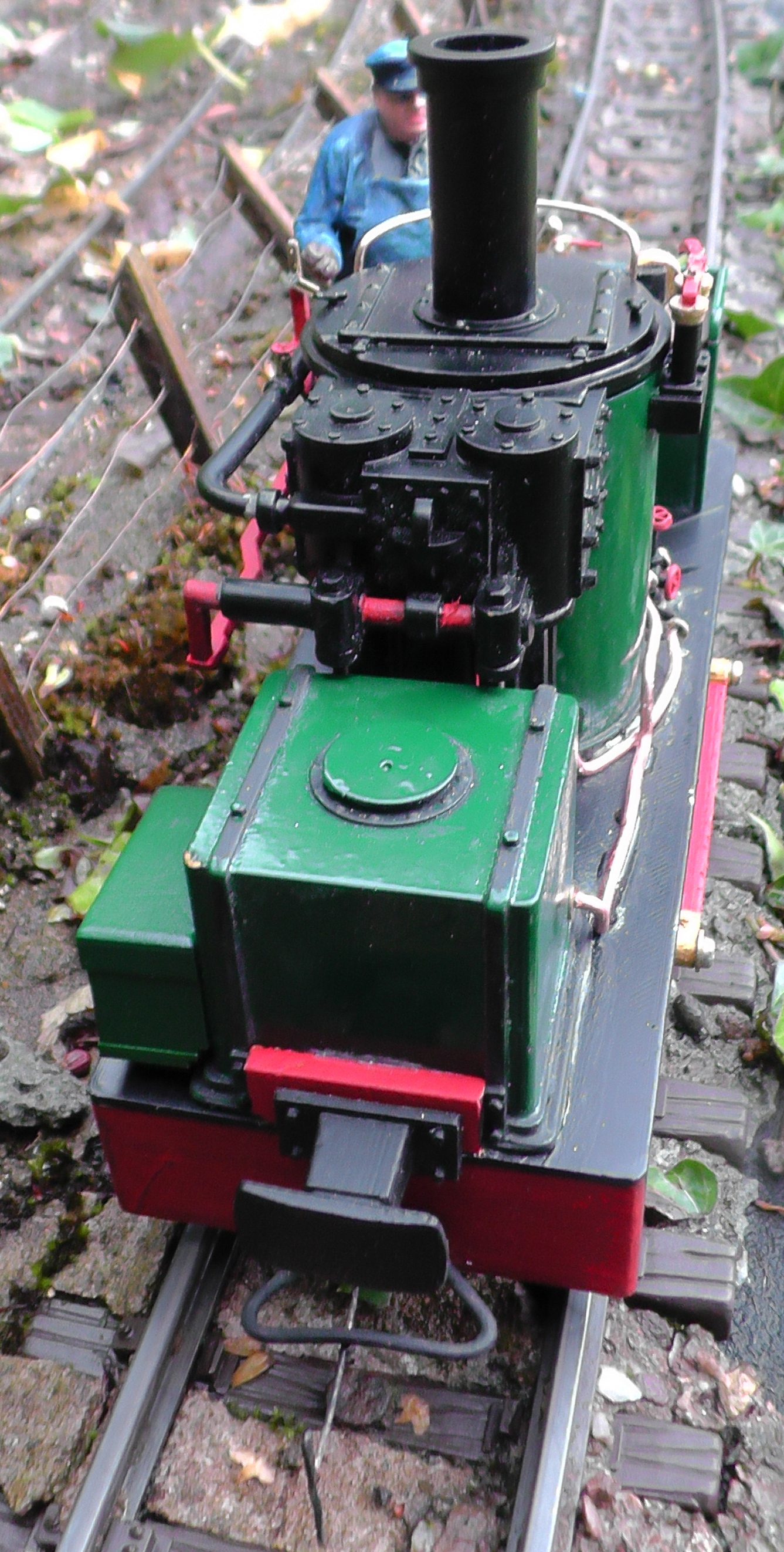
A 3D printed driver from DesignScantPrint3D was acquired, painted and glued into place, ........

.... and the loco given a test-run.
Satisfied that all was functioning as it should, pipework was made from lengths of copper wire extracted from some household mains twin-and-earth cable.

My own design of buffers were printed out .....

.... and mounted on buffer beam extensions to ensure they were the correct height to match with the rest of my rolling stock.


As there was insufficient space behind the buffer-beams for my usual home produced LGB compatible hook and loop couplings,


These were chemically blackened .........

... and mounted at the correct height above the rails, below the buffers.

More lead flashing was forced into the space beside the motor mount, ......

I could still do with finding more room for lead ballast - maybe in the bunker behind the sound card and maybe also inside the boiler. But for now, I am very happy with the loco's performance and appearance.


The 3D .STL files are freely available for download on the gardenrails.org forum. You will need to register with the forum to gain access to the download area and whilst there is no charge for the use of the forum, we hope you will make a small voluntary donation towards the running costs of the ad-free forum to reflect what you feel the files are worth.
