
Power was provided by two AA batteries mounted in a battery holder which was neatly slotted in at the back of the chassis

This was connected to a Double Pole Double Throw (DPDT) centre-off switch mounted beneath the driver's seat which acted as a reversing switch. There was no speed controller but the gearing allowed it to move at a fairly realistic speed.

After prising the driver away from his seat ....
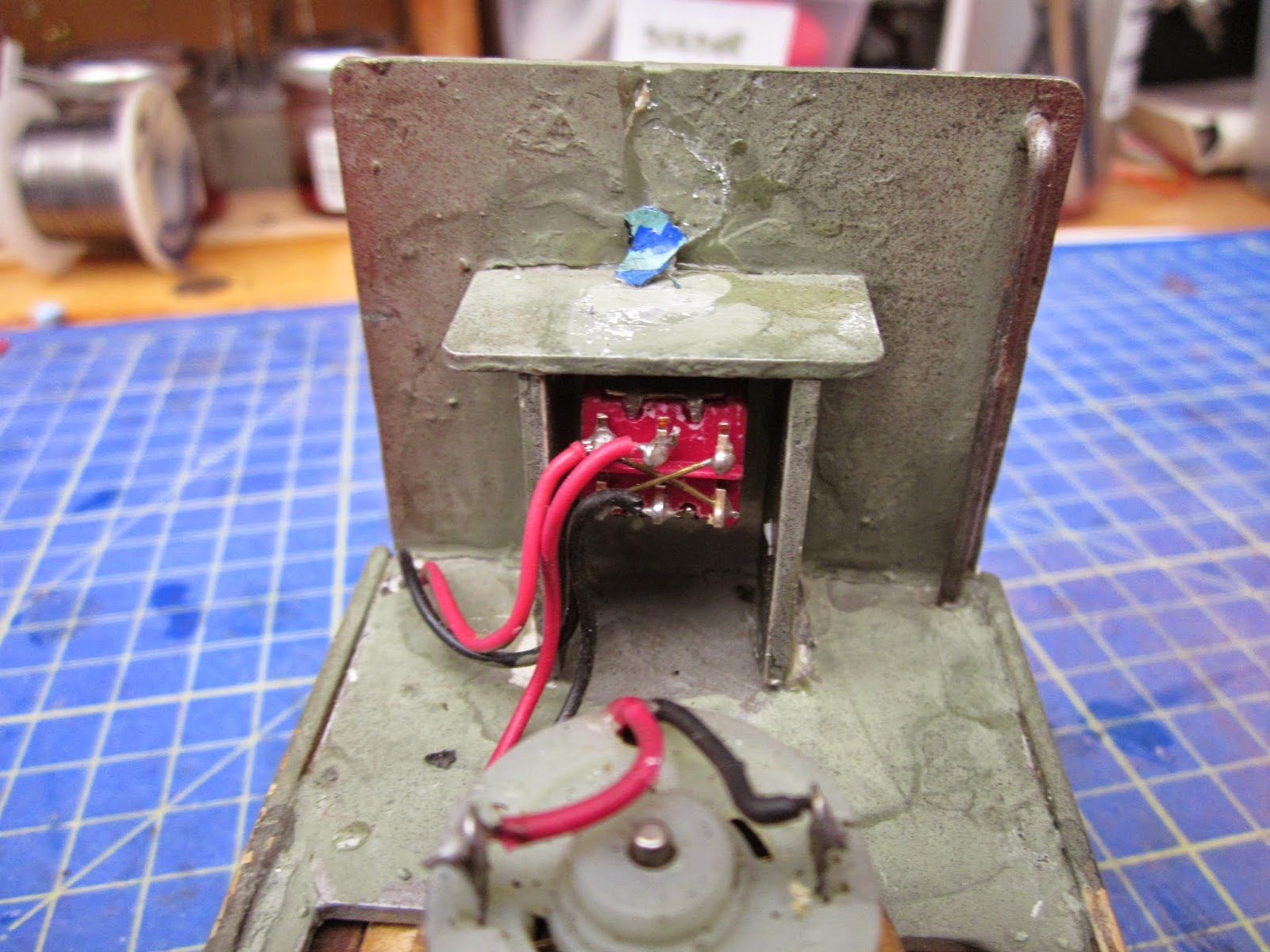
....... the leads were de-soldered from the reversing switch, the switch was removed and the cross-over wire carefully removed.

The switch was then rotated through 90 degrees so that down would be 'on', middle would be 'off' and up would be 'charge'. Two 1mm diameter holes were drilled just beneath the switch (at first these were too close together) and brass pins were passed through the holes.

A red and a black wire were soldered to the ends of the pins and the other ends soldered to the lower two terminals of the DPDT switch.

The pins were then fixed into place using epoxy resin. These pins will act as contacts for recharging (thanks to Greg Hunter of the Sandstone & Termite Railway for the idea).

The battery box was removed and a slot filed in the sides of the battery compartment.......

..... to accommodate a 18650 tagged lithium-ion battery.

Leads were soldered on to the tags and insulated with heatshrink tubing (this shrinks to half its size when heat is applied) .......

All but around 5mm was removed from the terminals of a 1.6A auto-reset fuse (from Maplin - part no. AK08J )......
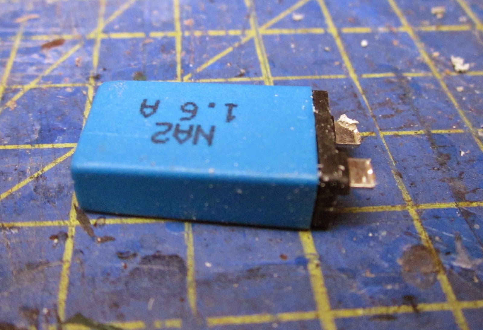
.... and the positive lead from the battery was was soldered to one of the terminals on the fuse and another lead was soldered on to the other tag ........

...... before being covered in heatshrink.

A slot was cut into the footplate beside the seat to accommodate the fuse, which was then fixed in place with a sticky-pad.

A cosmetic two gallon fuel can was made from 1mm thick offcuts of plasticard

..... to slide over the the fuse.

A 3mm dia hole was drilled in the centre of the battery compartment to take the wiring.

The battery was slotted into place and the wires taken through the hole and soldered to the middle two terminals of the DPDT switch.

A Deltang Rx65b receiver/controller was programmed to operate in auto-shuttle mode on receipt of a triggering signal from pad 8 (see How I re-programmed a Deltang Rx65b receiver/controller ). The diminutive receiver/controllers have now become the default radio control system on my railway after having evaluated various approaches (see An evaluation of Deltang radio control)
After some experimentation, it was found that interference from the motor kept falsely triggering the input on pad 8. Adding 0.1uF capacitors to the terminals of the motor proved ineffective .......

...... and so, following advice from David Theunissen at Deltang, a 0.1uF capacitor was soldered between pad 8 and one of the negative pads on the receiver.

A short length of screened cable was then soldered on to the legs of this capacitor. This would ultimately be connected to a reed switch (see below), thus enabling the auto-shuttle feature to be triggered with a magnet.

Holes were drilled in the footplate to take the power and trigger leads for the Deltang Rx65b receiver/controller.

The power leads were passed through from beside the motor, under the footplate to emerge again beside the switch.

The leads were then soldered to the upper terminals of the DPDT switch. When the switch is in its lower position, power will then flow to the receiver.

The motor leads from the receiver were then soldered to the terminals of the motor (after first checking with the transmitter which way round they needed to be to ensure the loco ran forwards when the speed knob on the transmitter was turned in the forwards direction).

The wires beneath the chassis were carefully routed to ensure they did not foul the motor, gears or wheels......

..... and then a small reed switch was soldered to the end of the screened cable.

These were then embedded in BluTak to allow for some adjustment and experimentation with the trigger magnets on the track. Periodically, the receiver and triggering signal were checked during the build to ensure that the position of the receiver and leads were not being affected by interference from the motor.

Magnets were temporarily wired to the sleepers of a test track to test-run the system - I found the magnets were attracted to the steel wheels of the loco if they weren't fixed down.

The loco was then test-run on the track.

Here's a video of the loco in action with the receiver programmed for a ten second stop at the end of each run.
There is still much to do. The loco needs a paint-job and weathering, the battery needs disguising as a fuel tank and various detailing bits and pieces of clutter need to be added to make the loco look as if it is serving a hard life at the copper mine. I am even considering adding a simple cab - something which the mine's blacksmith might have knocked-together to keep the drivers happy.

But I am very happy that I have been able to put the loco under radio control and automated control with the addition of one fairly inexpensive piece of technology.

2 comments:
Excellent conversion. Very impressive auto shuttle feature.
Thanks geon
It made sense to have this little diesel pottering about on the 32mm feeder without the need for direct control - though I can easily control it manually if I need to.
Rik
Post a Comment