The Rationale
When I set up my railway, I naively thought I would be able to operate it from one central position and so made a control panel which was situated in the corner of the leanto. In those early days, my locomotives were all track-powered and controlled by a couple of small LGB transformer controllers.
The trackplan was separated into five electrically isolated sections (switches A - E) and all nine points were operated by point motors using two-way centre-biased switches. There was also a reverse loop operated by a reversing switch.
However, I quickly realised that, not only was following trains around essential when running them in the garden, it was a lot more enjoyable. And so, I invested in various remote control systems using track power, culminating in DCC (see Digital Developments). I was quite satisfied with DCC for several years as it simplified the wiring around the garden (no need for isolated track sections) and I could operate the remote controlled points from the DCC handset. As the wiring to the point motors was already in situ, I placed the the points decoders (and the reverse loop controller) inside the now redundant control panel. This helped protect them from the elements.

Over the past three years, I have steadily experimented-with and ultimately adopted radio control and battery power. I was fed-up with constantly cleaning the track, tracing faulty electrical track joints and having locos grind to a halt when shunting or slow running. My biggest regret, though, was losing the ability to control my awkward-to-reach pointwork remotely from the DCC handset.
On my layout there are six turnouts which are difficult to access, marked in red on this trackplan.

Having sold off my DCC equipment, I ran the railway for a while by operating these points manually. Whilst this was possible, it was quite inconvenient. Most of these points needed to be changed repeatedly during an operating session and bending, reaching and stretching is something which is becoming increasingly difficult as I dodder into old age.
Having become of fan of Deltang radio control equipment for my locos, I was intrigued when David T (Mr Deltang) developed and produced a remote points controller using his 2.4gHz radio control system. It works by controlling servos which can be used to switch the blades of turnouts.
I considered replacing my existing LGB point motors with servos but the logistics of making the transition seemed daunting. For one thing, each servo would need three wires whereas the LGB point motors only require two. This would have entailed running additional wiring around the garden. Also, I was not certain how much the signal wire to each servo would be affected by the long run of wiring from the control box in the leanto to each turnout. The more I thought about it, the more unfeasible it became. "It's a pity the r/c unit couldn't be configured to operate LGB point motors," thought I.
I am in regular correspondence with a fellow garden railway modelling in Australia. Greg Hunter, whose Sandstone & Termite Railway has many similarities with mine, is a dab hand at anything electronic and has produced a series of online articles about using programming Picaxe micro-chips for controlling locos and lineside features. When I explained the situation he immediately concluded that, providing the Deltang receiver could provide binary on/off outputs rather than only servo signals, it would be feasible. The Rx105 receiver used with the unit comes in various configurations (including on/off 'lighting' outputs) and can be re-programmed by the user to provide any combination of outputs - and so the project looked distinctly doable.
The Transmitter
I sent off for the kit version of the Deltang Tx27 and the Rx105 receiver, which duly arrived (only £22 at the time of writing).
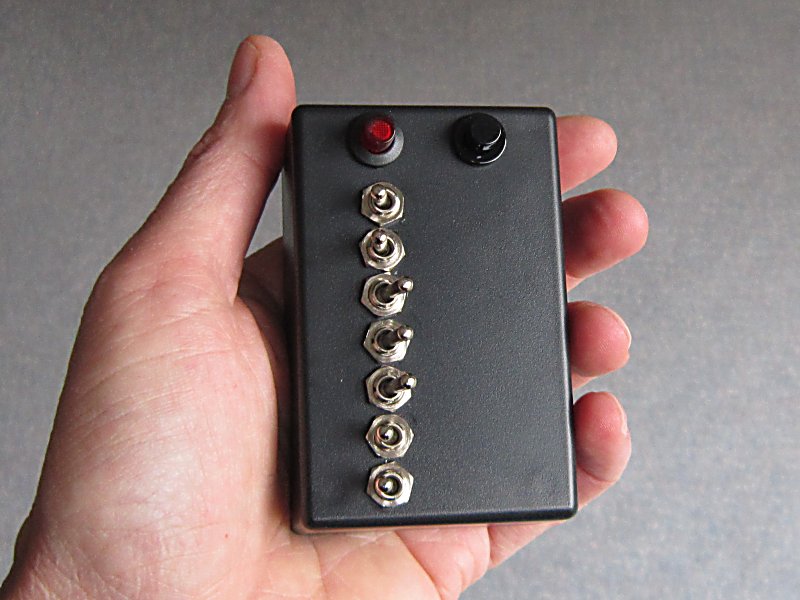
The most difficult stage of making the kit was to drill the holes in the ABS box. I marked these out in a pattern which would loosely represent the relative position of the pointwork on my layout, and drilled the 6mm diameter holes needed for the switches.

The switches were then inserted into the holes and the nuts tightened.

The connections were then wired to the relevant pins on the receiver, following the circuit diagram provided with the kit.

Once all the wiring had been completed, a PP3 battery was connected and the transmitter powered up. There was no way of testing it at that moment, but it seemed to be functioning as expected.

The switching system

The process
- When a switch (eg switch 2) is clicked on the the transmitter, a signal is sent to the receiver.
- The receiver sends a signal to the Picaxe board (eg input 2)
- On receipt of the signal, the Picaxe board checks which way the relevant point (eg Point 2) is already pointing.
- If the point needs reversing, the Picaxe board triggers the reversing relay on the relay board and then triggers the relevant relay (eg Relay 2) to send a 12v pulse to the point motor.
The Relay board
I next turned my attention to constructing the relay board needed to operate the point motors. With Greg's help, we had worked out that we needed six double pole on/off (DPST) relays to operate the six turnouts and a double-pole, double-throw (DPDT) relay to act as a reversing switch to send the point motor one way or the other. Hopefully, this circuit diagram helps explain the relay board's contribution to the system:
The six two pole on-off relays were soldered to a piece of Veroboard in two rows of three, and the DPDT relay beside them.

I tried to ensure that the terminals for the common connections on the relays (such as ground) were soldered to the same rails of the board.

The relays were then wired up - blue wires providing the 12v output to the point motors, the white wires receiving the 5v energising pulses for the relays from the Picaxe board.

The Picaxe-18 Project board was then wired up. The white wires from the point actuating relays were attached to outputs 0-5, and the reversing relay wire was attached to output 7. The white (signal) leads from six servo plugs were attached to inputs 0-2 and 5-7 (3 and 4 are not used for switched inputs) and a 5v voltage regulator with smoothing capacitors was mounted on another piece of Veroboard and connected to the Picaxe board using the 12v supply from an old Scalextric transformer. This also supplies the current needed to switch the point motors.

The 12v supply was then connected to the point actuating relays (the purple wire).

A test program was uploaded to the Picaxe board to check that our logic was correct and the circuitry was given a test run with a spare point motor connected in turn to each of the relay outputs.

The Picaxe was then loaded with the full program and tested, before the assembly was connected to the wiring for the point motors and placed in the control box.

The Picaxe Program
The program for the Picaxe controller uses two main procedures - one to check the initial state of the switches on the transmitter when powered up - and the main, continuously looping procedure which keeps checking for a change in the position of any of the switches on the transmitter.On power-up the Picaxe checks the existing state of outputs from the receiver and switches each of the relays (and hence the point motors in turn). This ensures that whichever way the switches are pointing on the transmitter, matches the way the points are switched.
Here is the initial checking procedure:
Once the checking procedure has completed, the main procedure is executed. This continually checks the state of the inputs from the receiver (and hence the transmitter) and if it detects a change, it instructs the relevant relay to send a pulse of 12v to the point motor.
'Program for relay control of point motors using Deltang Tx27 and Rx105-7
'Pin allocation
'pinC.0 input1
'pinC.1 input2
'pinC.2 input3
'pins C.3 and C.4 cannot be used as inputs
'pinC.5 input4
'pinC.6 input5
'pinC.7 input6
'pinB.0 output1
'pinB.1 output2
'pinB.2 output3
'pinB.3 output4
'pinB.4 output5
'pinB.5 output6
'pinB.7 DPDT relay
'ASSUME when input transition is low to high, switch left
'and when input high to low transistion, switch right
'Variables
symbol oldinput1=b6
symbol oldinput2=b7
symbol oldinput3=b8
symbol oldinput4=b9
symbol oldinput5=b10
symbol oldinput6=b11 'the last read state of the input pins
'++++++++++++++++++++++++++++++++++++++++++++++++++++++++++++++++++
'This is to set the turnout to the input conditions of the receiver at turnon.
initialize:
'if it's a low input at turn on, switch right.
'if it's high, switch left.
if pinC.0 = 1 then 'checks the input to see if it is high and if so .....
oldinput1 = 1 'stores the state of the switch for future reference
high B.7 'energises the reversing relay
pause 100
high B.0 'energises the points relay 1
pause 500 'for half a second
low B.0 'then turns the relay off
pause 100
low B.7 'and turns the reversing relay off
else 'otherwise .....
oldinput1 = 0 'stores the state of the switch
low B.7 'makes sure the reversing relay is off
pause 100
high B.0 'switches on the relay for point 1
pause 500 'for half a second
low B.0 'then switches it off
endif
.
.
'This procedure is now repeated for each of the inputs and outputs with similar blocks of code
start:
'1st relay
if pinC.0 = 1 and oldinput1 = 0 then 'checks if the switch on the tx has moved, if so ...
oldinput1 = 1 'stores the new position of the switch
high B.7 'switches on the reversing relay
pause 100 'for a second
high B.0 'switches on the relay for point 1
pause 500 'for half a second
low B.0 'switches off relay 1
pause 100
low B.7 'switches off the reversing relay
elseif pinC.0 = 0 and oldinput1 = 1 then 'checks if the tx switch is the other way
oldinput1 = 0
low B.7
pause 100
high B.0
pause 500
low B.0 endif
.
.
'The above block of code is replicated for each of the remaining sets of inputs and outputs.
.
.
goto start
'=======================
And that's basically all there is to it .......
Two of the outputs switch two point motors - the crossover at the back of the garden and the mine link. I have now also fitted a Capacitor Discharge Unit into the 12v supply for the point actuating relays to ensure these motors get the extra kick needed. It wasn't essential, they were switching successfully, but I happened to have a spare left over from my indoor 00 layout.
6 comments:
Rik,
Thanks this is really helpful, l have bought the picaxe, and am getting all the rest of the stuff together. I have spent nearly an hour trying to ID the relays (there are so many available!) could I trouble you for a part number for both the DPDT & THE DPST?
Your blog is an inspiration thank you!
James
Hi James
Email sent. I bought both cheaply on eBay. Any 12v relay should do the job.
Hello Rik,
Once again your pioneering has found use on my railway!
I moved house and hence a new layout is beginning, using the reclaimed track from before which includes LGB point motors in a location far from any mains power.
I had previously controlled a pair of these motors via a DPDTCO switch and 9v PP3 on a portable layout, but I needed a more permanent solution here.
Using your method, I've employed a DelTang TX2 with the RX105-3 replacement MR003, sending signals to an Arduino Pro-Micro and a collection of four dual H-Bridges. I'm using a 3S LiPo for power. The H-Bridges are solid state so I can avoid relays, hopefully adding to their weather-proofness. I had great fun programming the Arduino so that it operates as intended, including a setup routine that flips each point on startup by way of operation test, plus firing each point in a pair separately to reduce the current draw.
Once again, thanks for the inspiration - happy to share any coding or discoveries if you like.
Paul
CSLR (now in Wales)
Thanks for that info, Paul. Your solution sounds quite ingenious - particularly the elimination of relays and firing the paired points sequentially to minimise current draw.
I'd be happy to include a fuller description of your version on my blog if you want to share it with the world at large.
Rik
Hello Rik. I'm currently creating the transmitter - I need to contain it all within a suitable enclosure: once done I will send you the details on components and programming etc. My choice of 'ground station' building is only just large enough hence the wiring looks somewhat spaghetti-like at the moment so i will attempt to make it look more professional!
Paul
Sounds interesting, Paul. Some of my wiring resembles spaghetti junction at times.... 😏
Post a Comment