Having recently constructed a Houstoun Gate Loco Works (HGLW) kit (see How I constructed an HGLW loco kit ), I thought I would build a similar IP Engineering kit for comparison. In this blog post, I will focus more closely on the installation of Deltang radio control, as I know that this aspect is something which some modellers find daunting.


The kit was well packed with a clear set of instructions.

It wasn't until I had separated all the parts from the frets and tidied them up that I realised I had been sent two identical frets (with the cab front and running plate) and was missing the fret containing the motor bonnet.
An email to Ivan at IP Engineering resulted in the missing fret being sent a couple of days later - and so construction could begin.

Then the bonnet front and sides were glued on.

The top of the bonnet is formed from two pieces of ply glued together .......

..... which then had its sides chamfered with a sandpaper block.

Two side pieces were then glued beneath the bonnet lid.

Another piece of ply was then glued between the side pieces as shown. The instructions were slightly unclear as to exactly where this piece was to be mounted, but it became apparent that this projecting piece would enable the lid to engage with the lower section of the bonnet.

The front of the bonnet was glued on, acting as a surround for the radiator.

The front buffer beam was then glued on ........

....... beneath the running plate.

The rear of the cab was then glued on, using medium thickness superglue and an accelerator spray.

The main structure of the body was now complete.


Rather than gluing the roof on to the cab as per the instructions, I decided I would like to have the roof removable to enable me to add details to the cab interior at a later date.

These supports were then cut out .........

And glued to a ??mm x ??mm piece of 1mm thick plasticard, using styrene solvent adhesive.

When the solvent had set, the roof was test-fitted.

The body was now more or less complete. In hindsight, I should have painted the body at this stage before the chassis was added. However, I decided to press on with the build.


Once all four bushes had been fixed .......

.... the springs and hangers were glued into place.

When this had been repeated for all four wheels ......

...... the bearing plates were glued on.


The sides were now ready to be glued to the underside of the body, the axles needed to be prepared.

Using the jig which is supplied with the kit, ......

...... the wheels were pushed on to the ends of the axle. The same jig was used ensure the wheels were perfectly aligned for the unpowered axle.

The worm was pushed on to the motor shaft.

The axles were threaded into bushes on the chassis sides, and then the sides were glued into place under the body. As there are no locating tabs, the positioning of the sides needed to be done by eye. I used PVA to fix them in place, to allow fine adkustments to be made while the glue was setting.

Once the glue had set on the chassis sides, the motpr was slotted into place. To hold the motor in the correct position to align the the worm with the worm wheel, I inserted four cocktail sticks in the slots beside the motor and applied thin superglue to the four tabs pressing on the motor.


One of the chassis sides was gently prised off, the wheels on one end of each axle slid off and the two sprockets threaded on to the axles. The wheels were then pushed back on to the axles and the chassis reassembled. The chain was then shortened to fit between the sprockets and clipped back together over the sprockets. This latter procedure is always a bit fiddly, but is achievable with persistence.


Short lengths of orange, red and brown wire were soldered to the switch as shown (I use 7 / 0.2 hookup wire from Rapid - eg https://www.rapidonline.com/rapid-gw010435-equipment-wire-red-7-0-2-100m-reel-01-0435 . As in the picture, I connected the red wire to the centre pin on the switch.

Short lengths of 1.6mm heat-shrink tube were then threaded on the wires and heat applied (the flame from a disposable lighter) to shrink the wrap on to the soldered joints.

An 8mm hole was drilled into the base of the body midway between the axles on the same side of the body as the switch.

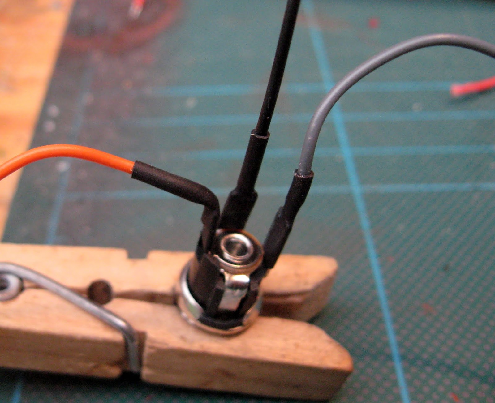
Three short lengths of hook-up wire were soldered on to the tabs on a 2.1mm DC socket as shown. A black wire was soldered to the middle pin, the other end of the orange wire from the two way switch was soldered to the left hand pin and a short length of grey wire soldered to the right hand pin. Short lengths of 2.4mm heat shrink tube was threaded over the joints and shrunk on using the disposable lighter flame.

The switch and socket were then mounted in their respective holes and their nuts tightened using pointed nosed pliers.


A 4mm hole was drilled in the base adjacent to the DC socket and the red and black wires threaded through.

Two unprotected 14500 (AA sized) tabbed li-ion batteries were acquired ( I get mine from Ecolux (Ecoluxshopdirect.co.uk ) as I know I can rely on their quality. Some of those sold on eBay are of dubious quality. If you cannot find tabbed batteries on the Ecolux website, you can request the addition of tabs for no extra charge.
NOTE: It is unlikely you will find protected li-ion batteries with tabs as they should not be connected together in packs.

As li-ion batteries supply 3.7v and the motor is rated at 3v, I connected the two batteries in parallel so they would provide 3.7v but give around twice the running time as using a single battery. The tabs on the negative ends of the batteries were connected with a black wire and the positive tabs of the batteries connected with a red wire.

The red lead from the two way switch was then connected to one of the positive tabs and the black lead from the charge socket was connected to one of the negative tabs of the batteries. I then snipped the red lead from the batteries at a suitable place and soldered in a 2A polyswitch, ......


 I decided to use a Deltang Rx65a receiver/controller with this model as I happened to have one to hand and I want to be able to program the receiver at a later date for auto-shuttle (see How I programmed a Deltang Rx65b for auto-shuttle).
The +ve power lead for the Rx65a was connected to the brown wire from the two-way switch and the -ve power lead of the Rx65b was connected to the grey lead from the charge socket.

The two white leads from the Rx65a were connected to the motor terminals.

The Rx65a was then tucked away beside the motor and it was then bound to one of my RC Trains/ Deltang transmitters.

The finished wiring loom therefore, looked like this:

The loco was then tested a few times to make sure everything was functioning as expected.
After some initial rubbing-down, the mechanism and the openings for the cab (ie windows and doorways) were masked with masking tape ......


.......and she was given a couple of coats of Halford's grey primer from an aerosol can.

When this had hardened off (after around 24 hours) she was rubbed down and Squadron White Putty filler applied where there were small cracks and dints in the surface. The primer tends to highlight these.


Once the filler had set she was rubbed down again and the chassis masked with tape before being given another couple of coats of primer, followed by a couple of coats of Halford's Rover Brooklands Green from another rattle can. This was allowed to harden off and then, as there were still some imperfections, White Putty filler was applied again and rubbed down once it had set.

Another couple of coats of primer, which was again rubbed-down, was followed by another couple of coats of Brooklands Green. Once hardened, this was very lightly rubbed down. The running plate was masked and then the exposed paintwork was given a couple of light coats of Halfords clear lacquer.

This was left to hard off and then the running boards and underframe were hand-painted with black acrylic paint to which a small amount of talcum powder had been added - to dull the gloss finish. The radiator opening was similarly picked out in black.
Cambrian Models rivet heads were glued on to the buffer beams .......

..... and the buffer beams painted with crimson acrylic paint.

The buffers and coupling hooks were similarly painted in acrylics.

The interior of the cab was hand-painted cream using acrylic paints and the brass wire (supplied with the kit) was bent into handrails and glued into the holes in the cab sides, with a couple of small brass washers on each handrail to simulate the mounting plates.

The cab roof was also painted matt black, though I usually add a few drops of silver paint to roofs as this gives them a slightly metallic finish.

To finish off, the spectacle rings were painted with brass colour paint (from the Plastikote range).


I decided to make the cab roof removable and to add Delrin chain and sprocket drive to improve her hauling capabilities. I have also added some lead weights to the bonnet lid and in various nooks and crannies to improve her adhesion, but she will happily haul the various lightweight wagons which I use on my 32mm gauge feeder line.

As can be seen. adding Deltang radio control is very straightforward, though she would just as happily trundle around with the supplied manual controls.

I would say that this loco would make an ideal introductory model for anyone wanting to explore the delights of garden railway modelling, without having to shell-out enormous amounts of cash when setting-up their first railway.


Contents
Introduction
The kit (complete with motor, wheels and gears) cost £45(at the time of writing) and arrived within a few days of ordering.
The kit was well packed with a clear set of instructions.

It wasn't until I had separated all the parts from the frets and tidied them up that I realised I had been sent two identical frets (with the cab front and running plate) and was missing the fret containing the motor bonnet.
The body
Firstly, the cab front and sides were added to the running plate.
Then the bonnet front and sides were glued on.

The top of the bonnet is formed from two pieces of ply glued together .......

..... which then had its sides chamfered with a sandpaper block.

Two side pieces were then glued beneath the bonnet lid.

Another piece of ply was then glued between the side pieces as shown. The instructions were slightly unclear as to exactly where this piece was to be mounted, but it became apparent that this projecting piece would enable the lid to engage with the lower section of the bonnet.

The front of the bonnet was glued on, acting as a surround for the radiator.

The front buffer beam was then glued on ........

....... beneath the running plate.

The rear of the cab was then glued on, using medium thickness superglue and an accelerator spray.

The main structure of the body was now complete.


Rather than gluing the roof on to the cab as per the instructions, I decided I would like to have the roof removable to enable me to add details to the cab interior at a later date.
The cab roof
Four curved supports for the roof were marked out on a piece of 1.5mm thick plasticard, using the rwar of the cab as a template.

These supports were then cut out .........

And glued to a ??mm x ??mm piece of 1mm thick plasticard, using styrene solvent adhesive.

When the solvent had set, the roof was test-fitted.

The body was now more or less complete. In hindsight, I should have painted the body at this stage before the chassis was added. However, I decided to press on with the build.

The chassis
The first task was to press the brass bushes into the holes in the chassis sides, and then fix them in place with a couple of dabs of thin superglue applied with a cocktail stick.
Once all four bushes had been fixed .......

.... the springs and hangers were glued into place.

When this had been repeated for all four wheels ......


The sides were now ready to be glued to the underside of the body, the axles needed to be prepared.
The mechanism
The first job was to push the worm wheel on to one of the axles until it was exactly in the centre.
Using the jig which is supplied with the kit, ......

...... the wheels were pushed on to the ends of the axle. The same jig was used ensure the wheels were perfectly aligned for the unpowered axle.

The worm was pushed on to the motor shaft.

The axles were threaded into bushes on the chassis sides, and then the sides were glued into place under the body. As there are no locating tabs, the positioning of the sides needed to be done by eye. I used PVA to fix them in place, to allow fine adkustments to be made while the glue was setting.

Once the glue had set on the chassis sides, the motpr was slotted into place. To hold the motor in the correct position to align the the worm with the worm wheel, I inserted four cocktail sticks in the slots beside the motor and applied thin superglue to the four tabs pressing on the motor.

The cocktail sticks were removed when the glue had set.

At this stage, I test-ran the loco. She ran quite sweetly, but could barely manage to haul three lightweight wagons. Having built an IP Engineering model previously, I realised she needed to have a four wheel drive mechanism added to improve her adhesion - eg see .....
4 wheel drive
From MotionCo, I ordered two 3mm bore, 8 tooth sprockets (http://www.motionco.co.uk/light-power-sprocket-bore-p-388.html ) and a one foot length of chain (http://www.motionco.co.uk/chain-sprockets-chain-c-21_23.html ).One of the chassis sides was gently prised off, the wheels on one end of each axle slid off and the two sprockets threaded on to the axles. The wheels were then pushed back on to the axles and the chassis reassembled. The chain was then shortened to fit between the sprockets and clipped back together over the sprockets. This latter procedure is always a bit fiddly, but is achievable with persistence.

The electrics
To mount a sub miniature two way single pole toggle switch, a 6.5mm hole was drilled in the base of the body between the leading axle and the front of the loco. On refection, this should have been midway between the axle and the front, as its present position makes it difficult to flick the switch.
Short lengths of orange, red and brown wire were soldered to the switch as shown (I use 7 / 0.2 hookup wire from Rapid - eg https://www.rapidonline.com/rapid-gw010435-equipment-wire-red-7-0-2-100m-reel-01-0435 . As in the picture, I connected the red wire to the centre pin on the switch.

Short lengths of 1.6mm heat-shrink tube were then threaded on the wires and heat applied (the flame from a disposable lighter) to shrink the wrap on to the soldered joints.

An 8mm hole was drilled into the base of the body midway between the axles on the same side of the body as the switch.

Three short lengths of hook-up wire were soldered on to the tabs on a 2.1mm DC socket as shown. A black wire was soldered to the middle pin, the other end of the orange wire from the two way switch was soldered to the left hand pin and a short length of grey wire soldered to the right hand pin. Short lengths of 2.4mm heat shrink tube was threaded over the joints and shrunk on using the disposable lighter flame.
The switch and socket were then mounted in their respective holes and their nuts tightened using pointed nosed pliers.


A 4mm hole was drilled in the base adjacent to the DC socket and the red and black wires threaded through.

Two unprotected 14500 (AA sized) tabbed li-ion batteries were acquired ( I get mine from Ecolux (Ecoluxshopdirect.co.uk ) as I know I can rely on their quality. Some of those sold on eBay are of dubious quality. If you cannot find tabbed batteries on the Ecolux website, you can request the addition of tabs for no extra charge.
NOTE: It is unlikely you will find protected li-ion batteries with tabs as they should not be connected together in packs.

As li-ion batteries supply 3.7v and the motor is rated at 3v, I connected the two batteries in parallel so they would provide 3.7v but give around twice the running time as using a single battery. The tabs on the negative ends of the batteries were connected with a black wire and the positive tabs of the batteries connected with a red wire.

The red lead from the two way switch was then connected to one of the positive tabs and the black lead from the charge socket was connected to one of the negative tabs of the batteries. I then snipped the red lead from the batteries at a suitable place and soldered in a 2A polyswitch, ......

..... covering the leads with heatshrink sleeving and then tucking it away so it was unobtrusive.

NOTE: I would normally include a battery protection board when using lithium-ion batteries as, in addition to protection from short circuits, the board prevents over-charging and over-discharge, which would ruin the batteries. However, I am using a Deltang Rx65a receiver/controller (see below) and an iMax B6 charger - the Rx65a (and all Deltang receivers) includes over-discharge protection for li-ion batteries and the iMax B6 carefully monitors the charging process.The polyswitch offers some protection against short-circuits.

Radio control
NOTE: The Deltang Rx65a has now been superseded by the more powerful and versatile Deltang Rx65b receiver/controller.
The +ve power lead for the Rx65a was connected to the brown wire from the two-way switch and the -ve power lead of the Rx65b was connected to the grey lead from the charge socket.

The two white leads from the Rx65a were connected to the motor terminals.

The Rx65a was then tucked away beside the motor and it was then bound to one of my RC Trains/ Deltang transmitters.

The finished wiring loom therefore, looked like this:

The loco was then tested a few times to make sure everything was functioning as expected.
Painting and finishing
Because the loco is constructed from plywood, she needed careful rubbing down with sanding blocks, emery papers and emery boards, before and between coats of paint.After some initial rubbing-down, the mechanism and the openings for the cab (ie windows and doorways) were masked with masking tape ......


.......and she was given a couple of coats of Halford's grey primer from an aerosol can.

When this had hardened off (after around 24 hours) she was rubbed down and Squadron White Putty filler applied where there were small cracks and dints in the surface. The primer tends to highlight these.


Once the filler had set she was rubbed down again and the chassis masked with tape before being given another couple of coats of primer, followed by a couple of coats of Halford's Rover Brooklands Green from another rattle can. This was allowed to harden off and then, as there were still some imperfections, White Putty filler was applied again and rubbed down once it had set.

Another couple of coats of primer, which was again rubbed-down, was followed by another couple of coats of Brooklands Green. Once hardened, this was very lightly rubbed down. The running plate was masked and then the exposed paintwork was given a couple of light coats of Halfords clear lacquer.

This was left to hard off and then the running boards and underframe were hand-painted with black acrylic paint to which a small amount of talcum powder had been added - to dull the gloss finish. The radiator opening was similarly picked out in black.
Cambrian Models rivet heads were glued on to the buffer beams .......

..... and the buffer beams painted with crimson acrylic paint.

The buffers and coupling hooks were similarly painted in acrylics.

The interior of the cab was hand-painted cream using acrylic paints and the brass wire (supplied with the kit) was bent into handrails and glued into the holes in the cab sides, with a couple of small brass washers on each handrail to simulate the mounting plates.

The cab roof was also painted matt black, though I usually add a few drops of silver paint to roofs as this gives them a slightly metallic finish.

To finish off, the spectacle rings were painted with brass colour paint (from the Plastikote range).

Conclusion
This was a delightful little kit to construct. The laser-cut pieces of the kit were well formed and needed only minimum effort to tidy up after being removed from the fret. The instructions are clear (apart from the section about the lid of the bonnet) and the various pieces fit together well - though a few more locating pegs or even marks would have assisted in making sure some parts were fitted appropriately.
I decided to make the cab roof removable and to add Delrin chain and sprocket drive to improve her hauling capabilities. I have also added some lead weights to the bonnet lid and in various nooks and crannies to improve her adhesion, but she will happily haul the various lightweight wagons which I use on my 32mm gauge feeder line.

As can be seen. adding Deltang radio control is very straightforward, though she would just as happily trundle around with the supplied manual controls.

I would say that this loco would make an ideal introductory model for anyone wanting to explore the delights of garden railway modelling, without having to shell-out enormous amounts of cash when setting-up their first railway.

2 comments:
Well Rik, that was another brilliant “How to”. I can see that the addition of the Rivet heads do make a big difference to the look of the little loco.
Thanks again Rik, although the electric side is still getting my head in a spin, I am getting there with it.
Thanks Rod
Doesn't take too long, but I think adding the rivet heads makes a world of difference to the buffer beams especially.
Rik
Post a Comment