I recently purchased a CTC DIY A8 3D printer (often advertised as an Anet A8 or Prusa i3 clone) and struggled to make sense of the assembly instructions. I thought others in a similar position might find my experiences helpful, having now put the kit together and got it working satisfactorily.

At first I was hesitant - surely at that price there must be a catch. I consulted a few members of the Garden Rails forum and the consensus seemed to be, why not give it a try as a sort of toe-dipping exercise. So I consulted the household authorities and was given the go ahead. A week had passed and the price had risen to £79.99 (and as you can see, two weeks later it has now risen to £92.39). I was reassured that it was coming from a UK supplier and so I wouldn't have to wait weeks or get stung for import duty if it had been sent direct from China. Three days later, a parcel arrived. It was a good job I had cleared it with the missus - its identity was emblazoned on the box for the world to see.

It was certainly well packed, but I was daunted by the sheer number of components - they weren't kidding when they described it as a DIY kit!

However, it was reassuring that they provided a couple of screwdrivers (and some Allen keys) ....

..... together with some assembly instructions in a Word file on a CD which was included with the kit.

As was suggested, I thoroughly read the instructions before tackling the kit. They seemed to have been translated from the original Chinese, maybe through Google Translate, so some of the phraseology was slightly obscure, but I felt the process was reasonably explicit and clear and so I set to work.
Immediately, I found that the instructions related to a different kit. The first three components described in the instructions were quite different to anything in the kit. So, I trawled the internet for something more suitable and discovered a video on YouTube depicting an employee of the CTC company constructing a printer which more closely resembled that in the kit.
However, the video was presented at double speed and omitted closeups at critical stages, so I was often baffled as to which components were being fitted, which way up they went and where exactly they were positioned. There were also a few differences between the components in the video and those supplied with the kit - as you will see below.
So, if you find yourself in a similar position, I hope this explanation as to how I assembled my printer will be useful. I made a few modifications during its construction and sometimes had to backtrack when I discovered I had made a mistake. Hopefully, I will help you avoid these errors.

Also needed were four M3 x 16 screws and four nuts.

The nuts were fitted into the two slots at the top of each side member. They are a very loose fit and so once inserted the pieces needed to be kept vertical to stop them from falling out (this becomes easier with practice).

The top piece of the printer was then slotted into tabs and screws tightened into the nuts using the screwdriver and fingers to hold the nuts in place. Note which way up the top piece faces.


Once both sides had been screwed into place.....

.... the front piece was identified .....

..... and similarly screwed into place with four M3 x 16 screws. Note: The two front pieces are symmetrical and so it didn't matter which way round they were fitted.

Next, the Y axis microswitch was identified (it has a Y tag on one of the leads), together with its mounting plate and two self tapping screws.


The switch was screwed to the mounting plate - note which way round it is fitted.

I then found one of the stepper motors with a cogged pulley, together with its mounting plate and bracket and four M3 x 8 screws with Allen socket heads.

NOTE: This was my first mistake. I hadn't noticed that the pulleys on the motors were different. The one on the left is the Y axis motor while the one on the right is the X axis motor. I didn't discover this difference until much later in the build.
 Make sure you use the motor with the pulley mounted as shown on the LEFT!
The motor was attached to the mounting plate as shown.

NOTE - The connector on the motor faces towards the larger part of the bracket - ie the base (something else I got wrong the first time!)


The motor support bracket was fitted into place first (M3 x 16 screws used throughout this stage).

...... followed by the motor bracket.

NOTE: The connector on the motor should be pointing towards the camera.

The mounting slot for the microswitch was then identified ......

..... and the microswitch fixed in place.

The rear chassis member was then screwed to the uprights.

The next stage was to construct the supports for the printer bed. The front chassis member for this was laid out .....

..... and the pulley and bracket assembly (mine was pre-assembled and in a packet).

The pulley bracket was attached to the front panel.

.... with M3 x 16 screws and nuts in the usual way.

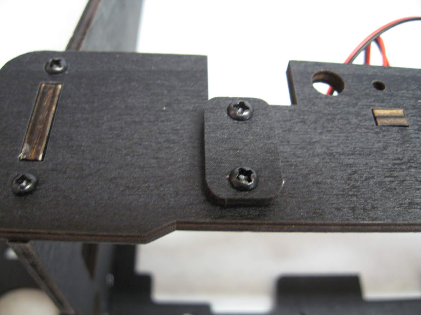
Two rectangular retaining plates were then selected, together with eight M3 x 16 screws and nuts.

The plates were mounted on the ends of the front support member
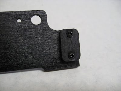
..... blanking off the holes for the spacer two rods. this is where the additional instructions supplied with my kit varied from those shown in the video. the video showed two long 8mm diameter threaded rods and six 8mm nuts and washers being attached to the large holes. if your kit includes four threaded rods then you need to refer to the manufacturer's video at this point.

Another two blanking plates .....

...... were attached to cover the 9mm holes .......

....... in the chassis back cross member.

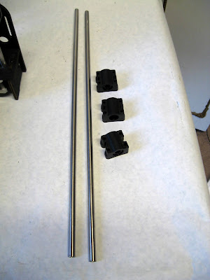
following the appended instruction sheet, two smooth rods were then threaded into the holes in the middle chassis cross member and butted up to the retaining plates in the end members - as shown in the photo.

No instructions were provided as to how the front chassis member should be fixed in place - I can only assume that it was meant to be held there by the tension in the toothed belt running between the stepper motor pulley at the back and the pulley at the front. This seemed to me to be very unsatisfactory and so I decided to add my own timber strut linking the front chassis member to the middle chassis member.
A 229mm long piece of 34mm x 15mm pine wood was cut ....
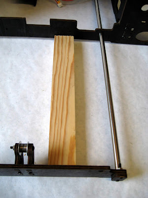
..... to fit between the middle and front chassis members as shown. Initially, I screwed this adjacent to the pulley bracket ......

...... however, this proved to be inadequate to hold the side rods in place, and so later it was moved to be adjacent to the side rod and another 229mm long piece of timber was fixed beside the other side rod - as shown here. This greatly improved the rigidity and integrity of the structure.

Next, the two upper brackets for the Z-axis screws were located ......

..... and screwed to the top corners of the frame.


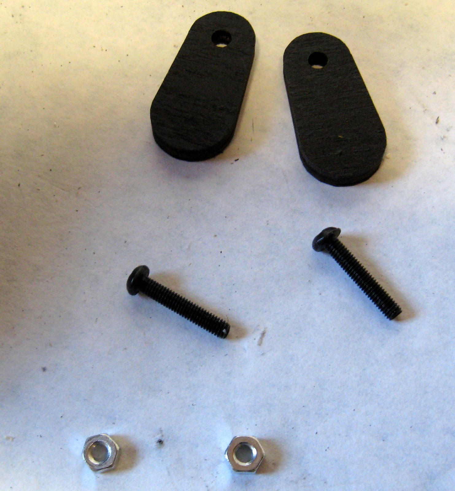
Four M3 x 16 screws and four nyloc nuts were extracted from their packs .....

..... and the four oval shaped belt retaining clamps fitted to the centre of the baseplate. These were left as a loose-fit at this stage.

The four plastic runners were then bolted to the baseplate, mounted on their four wooden pedestals using M3 x 20 screws.

The oval retaining plates ........

...... were then attached to the front and rear chassis members with M3 x 8 screws

.... so they could be swung to cover the holes for the Y axis rods.

The polished rods were then slid into the holes in the chassis and through the plastic sliders on the base of the printbed baseplate.

The baseplate was slid back and forth a few times to make sure it was running smoothly on the rods. You might need to adjust the screws on the plastic sliders if you find any of them is binding on the rods.
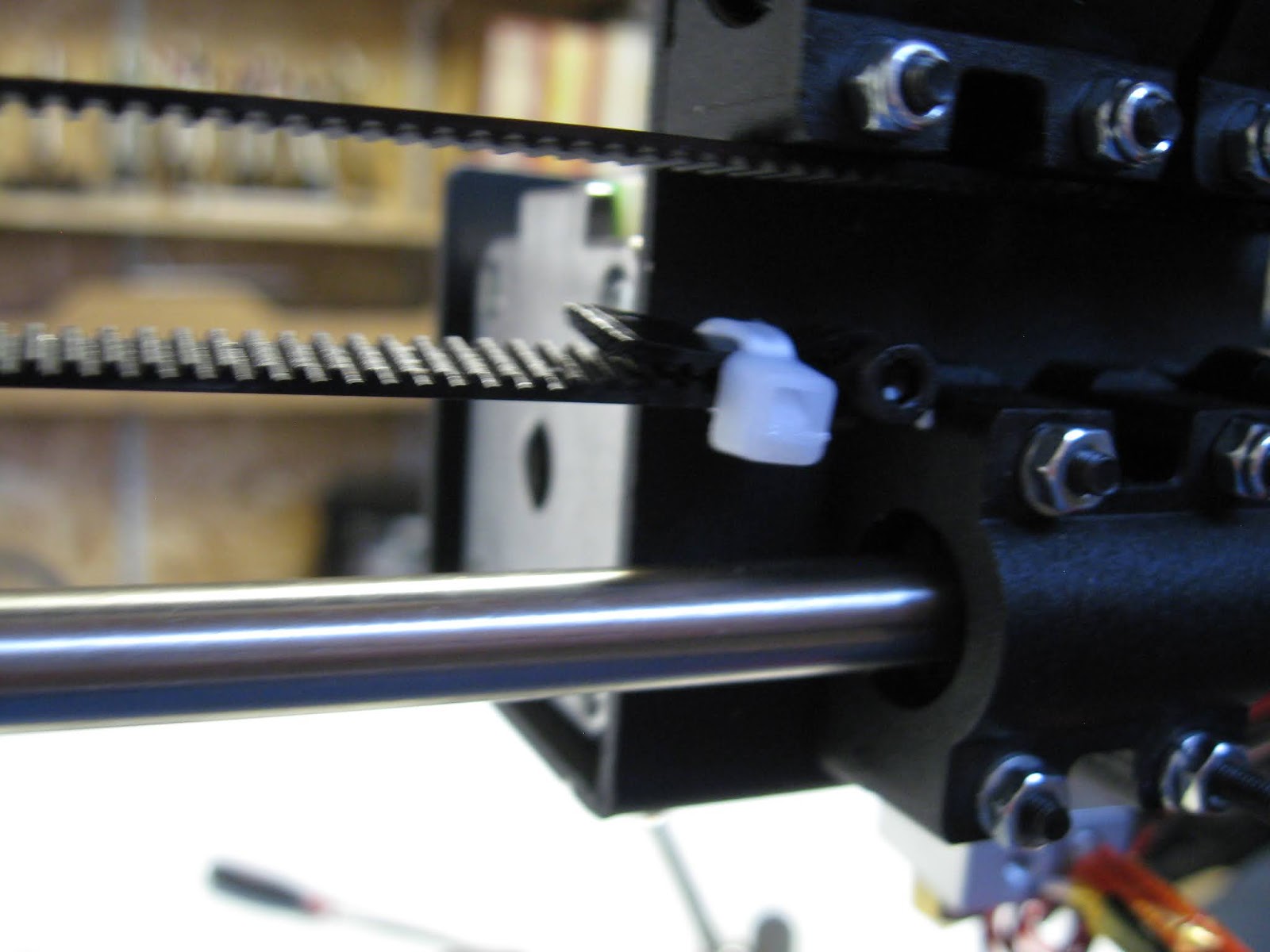
The toothed-belt was then clamped under the baseplate ........

..... and threaded through the pulley on the Y axis motor ......

..... and through the pulley on the front of the printer .....

..... before being pulled tight, clamped under the other bracket and trimmed to length.

NOTE: I found it was easier to slacken off the screws holding the pulley bracket on the front of the printer chassis before clamping the belt. I could then tension the belt by tightening the screws on the pulley bracket.
Four M3 x 30 countersunk headed screws were then found, together with four wing-nuts and springs.

The printbed .......

...... was then attached to the mounting plate .....

....using the holes in each corner.


...... and its mounting plates were then located. The microswitch was screwed to the mounting plate ......

..... with a couple of short self tapping screws ......

..... and a couple of M3 x 12 screws were used (with washers which were not in the kit) .....

...... to mount the switch in the slots on the left-hand chassis plate.

If I had had more wing-nuts, I would have used them as this would make the adjustment of the microswitch at lot easier.


...... together with eight M3 x 4 screws and the Allen key needed to tighten them.

The motors were attached to the brackets .......


..... and the side-plates located.

The sideplates were attached to the brackets with M3 x 8 screws and nuts in the usual way.


The motors were then attached to the side members of the chassis ........

.... using more M3 x 8 screws and nuts.


The retaining plates for the vertical polished rods were then .......

...... screwed into place on the top brackets .......

.... and the rods slid down into place ........

...... threading the two X-axis plastic brackets on to them .......


..... before being held in place by sliding the retaining plates over.

The M8 threaded rods were then passed through the holes in the top bracket and screwed down into the threaded bushes in the plastic X-axis brackets.

The bottom of each threaded rod was then slotted into the ferrules on the motor shafts and held in place with the grub screws using the relevant Allen key to tighten them.


NOTE: At a later date, I flattened off the ends of the threaded rods with a file to help the grub screws hold the rods more steadily. I found rods tended to work loose otherwise.

The rods were slid into the holes in the plastic X-axis brackets and the sliders put on to the rods.


The grub screws on brackets were then tightened with an Allen key .....

..... to hold the rods tightly in place.

The stepper motor for the X-axis (note the way the pulley is mounted) ......

.... was attached to the plastic brackets with four M3 x 20 screws.


Then the printhead bracket was attached to the sliders on the X-axis rods using M3x20 screws ......

.... and nyloc nuts.

The X-axis microswitch ........

..... was screwed to the holes in the top of the left hand X-axis plastic bracket with self tapping screws.

Contents
- Introduction
- Assembly
- The frame
- The printbed
- The Z-axis microswitch
- The Z-axis motors and drive rods
- The X-axis motor and printhead carriage
- The Printhead assembly
- The power supply
- The motherboard
- Wiring-up
- Conclusion
- Part 2 - Setting up the printer
- Part 3 - How I improved the printer - pending
Introduction
I have long been fascinated by the concept of 3D printing but could never really justify the £500+ price tag, so when I saw a printer on eBay with a price tag of £69.99 I was tempted.
At first I was hesitant - surely at that price there must be a catch. I consulted a few members of the Garden Rails forum and the consensus seemed to be, why not give it a try as a sort of toe-dipping exercise. So I consulted the household authorities and was given the go ahead. A week had passed and the price had risen to £79.99 (and as you can see, two weeks later it has now risen to £92.39). I was reassured that it was coming from a UK supplier and so I wouldn't have to wait weeks or get stung for import duty if it had been sent direct from China. Three days later, a parcel arrived. It was a good job I had cleared it with the missus - its identity was emblazoned on the box for the world to see.

It was certainly well packed, but I was daunted by the sheer number of components - they weren't kidding when they described it as a DIY kit!

However, it was reassuring that they provided a couple of screwdrivers (and some Allen keys) ....

..... together with some assembly instructions in a Word file on a CD which was included with the kit.

As was suggested, I thoroughly read the instructions before tackling the kit. They seemed to have been translated from the original Chinese, maybe through Google Translate, so some of the phraseology was slightly obscure, but I felt the process was reasonably explicit and clear and so I set to work.
Immediately, I found that the instructions related to a different kit. The first three components described in the instructions were quite different to anything in the kit. So, I trawled the internet for something more suitable and discovered a video on YouTube depicting an employee of the CTC company constructing a printer which more closely resembled that in the kit.
However, the video was presented at double speed and omitted closeups at critical stages, so I was often baffled as to which components were being fitted, which way up they went and where exactly they were positioned. There were also a few differences between the components in the video and those supplied with the kit - as you will see below.
So, if you find yourself in a similar position, I hope this explanation as to how I assembled my printer will be useful. I made a few modifications during its construction and sometimes had to backtrack when I discovered I had made a mistake. Hopefully, I will help you avoid these errors.
How I assembled my printer
The frame
The first stage was to identify the three main structural components.
Also needed were four M3 x 16 screws and four nuts.

The nuts were fitted into the two slots at the top of each side member. They are a very loose fit and so once inserted the pieces needed to be kept vertical to stop them from falling out (this becomes easier with practice).

The top piece of the printer was then slotted into tabs and screws tightened into the nuts using the screwdriver and fingers to hold the nuts in place. Note which way up the top piece faces.


Once both sides had been screwed into place.....

.... the front piece was identified .....

..... and similarly screwed into place with four M3 x 16 screws. Note: The two front pieces are symmetrical and so it didn't matter which way round they were fitted.

Next, the Y axis microswitch was identified (it has a Y tag on one of the leads), together with its mounting plate and two self tapping screws.


The switch was screwed to the mounting plate - note which way round it is fitted.

I then found one of the stepper motors with a cogged pulley, together with its mounting plate and bracket and four M3 x 8 screws with Allen socket heads.

NOTE: This was my first mistake. I hadn't noticed that the pulleys on the motors were different. The one on the left is the Y axis motor while the one on the right is the X axis motor. I didn't discover this difference until much later in the build.

The motor was attached to the mounting plate as shown.

NOTE - The connector on the motor faces towards the larger part of the bracket - ie the base (something else I got wrong the first time!)

The rear of the printer chassis was then taken from the box ....

The motor support bracket was fitted into place first (M3 x 16 screws used throughout this stage).

...... followed by the motor bracket.

NOTE: The connector on the motor should be pointing towards the camera.

The mounting slot for the microswitch was then identified ......

..... and the microswitch fixed in place.

The rear chassis member was then screwed to the uprights.


..... and the pulley and bracket assembly (mine was pre-assembled and in a packet).

The pulley bracket was attached to the front panel.

.... with M3 x 16 screws and nuts in the usual way.

Two rectangular retaining plates were then selected, together with eight M3 x 16 screws and nuts.

The plates were mounted on the ends of the front support member

..... blanking off the holes for the spacer two rods. this is where the additional instructions supplied with my kit varied from those shown in the video. the video showed two long 8mm diameter threaded rods and six 8mm nuts and washers being attached to the large holes. if your kit includes four threaded rods then you need to refer to the manufacturer's video at this point.

Another two blanking plates .....

...... were attached to cover the 9mm holes .......

....... in the chassis back cross member.
following the appended instruction sheet, two smooth rods were then threaded into the holes in the middle chassis cross member and butted up to the retaining plates in the end members - as shown in the photo.

No instructions were provided as to how the front chassis member should be fixed in place - I can only assume that it was meant to be held there by the tension in the toothed belt running between the stepper motor pulley at the back and the pulley at the front. This seemed to me to be very unsatisfactory and so I decided to add my own timber strut linking the front chassis member to the middle chassis member.
A 229mm long piece of 34mm x 15mm pine wood was cut ....

..... to fit between the middle and front chassis members as shown. Initially, I screwed this adjacent to the pulley bracket ......

...... however, this proved to be inadequate to hold the side rods in place, and so later it was moved to be adjacent to the side rod and another 229mm long piece of timber was fixed beside the other side rod - as shown here. This greatly improved the rigidity and integrity of the structure.

Next, the two upper brackets for the Z-axis screws were located ......

..... and screwed to the top corners of the frame.


The printbed
The mounting plate for the printbed was tackled next.
Four M3 x 16 screws and four nyloc nuts were extracted from their packs .....


The oval retaining plates ........

...... were then attached to the front and rear chassis members with M3 x 8 screws

.... so they could be swung to cover the holes for the Y axis rods.

The polished rods were then slid into the holes in the chassis and through the plastic sliders on the base of the printbed baseplate.

The baseplate was slid back and forth a few times to make sure it was running smoothly on the rods. You might need to adjust the screws on the plastic sliders if you find any of them is binding on the rods.
The toothed-belt was then clamped under the baseplate ........

..... and threaded through the pulley on the Y axis motor ......

..... and through the pulley on the front of the printer .....

..... before being pulled tight, clamped under the other bracket and trimmed to length.

NOTE: I found it was easier to slacken off the screws holding the pulley bracket on the front of the printer chassis before clamping the belt. I could then tension the belt by tightening the screws on the pulley bracket.
Four M3 x 30 countersunk headed screws were then found, together with four wing-nuts and springs.

The printbed .......

...... was then attached to the mounting plate .....

....using the holes in each corner.

The Z axis microswitch
The z-axis microswitch .......
...... and its mounting plates were then located. The microswitch was screwed to the mounting plate ......

..... with a couple of short self tapping screws ......

..... and a couple of M3 x 12 screws were used (with washers which were not in the kit) .....

...... to mount the switch in the slots on the left-hand chassis plate.

If I had had more wing-nuts, I would have used them as this would make the adjustment of the microswitch at lot easier.


Z axis motors
The Z axis motors and their mounting brackets were located next ....
...... together with eight M3 x 4 screws and the Allen key needed to tighten them.

The motors were attached to the brackets .......


..... and the side-plates located.

The sideplates were attached to the brackets with M3 x 8 screws and nuts in the usual way.


The motors were then attached to the side members of the chassis ........

.... using more M3 x 8 screws and nuts.


The retaining plates for the vertical polished rods were then .......
...... screwed into place on the top brackets .......

.... and the rods slid down into place ........

...... threading the two X-axis plastic brackets on to them .......


..... before being held in place by sliding the retaining plates over.

The M8 threaded rods were then passed through the holes in the top bracket and screwed down into the threaded bushes in the plastic X-axis brackets.

The bottom of each threaded rod was then slotted into the ferrules on the motor shafts and held in place with the grub screws using the relevant Allen key to tighten them.


NOTE: At a later date, I flattened off the ends of the threaded rods with a file to help the grub screws hold the rods more steadily. I found rods tended to work loose otherwise.

The X-axis carriage and motor
The polished rods for the X-axis an the plastic sliders were then sorted out.
The rods were slid into the holes in the plastic X-axis brackets and the sliders put on to the rods.


The grub screws on brackets were then tightened with an Allen key .....

..... to hold the rods tightly in place.

The stepper motor for the X-axis (note the way the pulley is mounted) ......

.... was attached to the plastic brackets with four M3 x 20 screws.


.... and nyloc nuts.

The X-axis microswitch ........

..... was screwed to the holes in the top of the left hand X-axis plastic bracket with self tapping screws.

The fan, cooling fins and safety grille ........

...... were loosely assembled with two M3 x 30 screws

The lower part of the extruder was carefully removed from its stepper motor (the spring can shoot off across the room!!) using an Allen key.


And then it can be re-assembled using the two screws on the fan assembly to hold it back into place.

The broad-headed screw on the base of the printhead assembly was then unscrewed slightly .......

..... to allow the printhead to be slotted into the bracket on the X-axis sliders.

The broad headed screw was then tightened to hold the printhead in place.

Two M3 x 12 screws were screwed into the back of the X-axis slider bracket......

...... and a loop made at one end of the remaining piece of toothed belt, using a cable tie to fasten it together.

The loop was then passed over one of the screws on the back of the bracket ......

..... threaded around the toothed pulley on the X-axis motor ......

...... around the pulley on the other bracket .........

...... then tensioned and looped around the other screw on the back of the printhead bracket.

As with the other end of the belt, the loop was held in place with a cabe-tie.

NOTE: It is easier to thread the belt over the pulley if the X-axis motor is unscrewed, the belt looped into the space and the motor replaced.
The ducted printhead cooling fan .......

.... was fitted with its 3D printed nozzle .......

...... before being screwed to the front of the printhead carriage with two M3 x 10 screws.

As can be seen, the printer was now taking shape.
The screws were passed through the holes in the top chassis plate and the spacers slid on.

The LCD panel was then attached ......

...... and its backing plate slotted on.
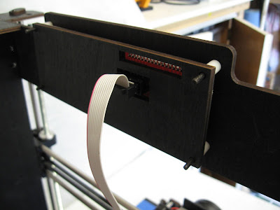
The nuts were then tightened on the screws to hold the panel into place.


Fortunately, the connectors are clearly labelled and so the leads from the socket were attached to the live (red), neutral(black) and earth(yellow) connectors on the left of the supply and the neutral and live output leads connected to the screws on the right - as shown below.

The plastic cover was then slotted over to help prevent electric shocks.

Three M3 x 8 screws and washers were found ......

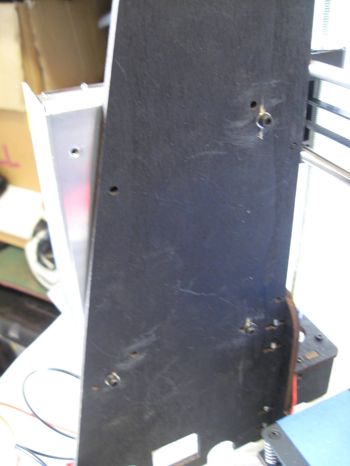
..... but I was unable to find three holes in the right-hand side panel of the chassis in the right places for mounting the supply and so had to drill my own.


The power supply was then attached to the panel

There was a square hole beneath the power supply which matched the size of the mains socket, but no holes for the screws.

So, a couple of 3-5mm holes were drilled in the relevant places .......

.... and the socket attached with a couple of M3 x 8 screws and nuts.


Fortunately, there were some holes in the right places in the left hand chassis upright and so the screws were threaded through and the spaces slotted on .....

..... and the motherboard screwed into place.

I decided to add some washers to avoid putting too much stress on the PCB.

Firstly the two-pin microswitch leads were connected to the sockets on the right of the board. The plugs have lugs which correspond to slots on the sockets and so they can't be connected the worong way round.
The plug from the X-axis miroswitch went in first ........

..... followed by the Y-axis ........

..... and the Z.

Next came the thermistor for the heated printbed (BT) .......

..... followed by the thermistor for the extruder (ET).

Then came the four-pin connectors on the left of the board leading to the motors.
Firstly the lead for the motor on the printhead extruder (E motor).

..... which was then attached to the connector on the motor on the printhead carriage(again, it can only be inserted the right way round).

Then came the right hand Z motor ....

..... which was attached to the motor on the right hand side of the printer as it faces you.

The left-hand Z motor was connected next .....


Next, the Y-axis motor on the back of the printer was connected ......

..... to the board.

And then the X axis motor which moves the printhead carriage to and fro .....

..... was connected.

The lead from the fan on the front of the printhead carriage ........

.... was connected to the right hand socket beneath the X-Motor socket.

While the lead from the fan on the side of the printhead carriage ......

.... was connected to the left hand socket.

The two output leads from the power supply ..........

...... were connected to the power terminals on the bottom right hand corner of the board - making sure the polarity was correct.

The leads from the heated printbed ...........

....... were then connected to the BED terminals as shown.

And the leads from the hot end of the extruder ........

.... were connected to the remaining terminals.

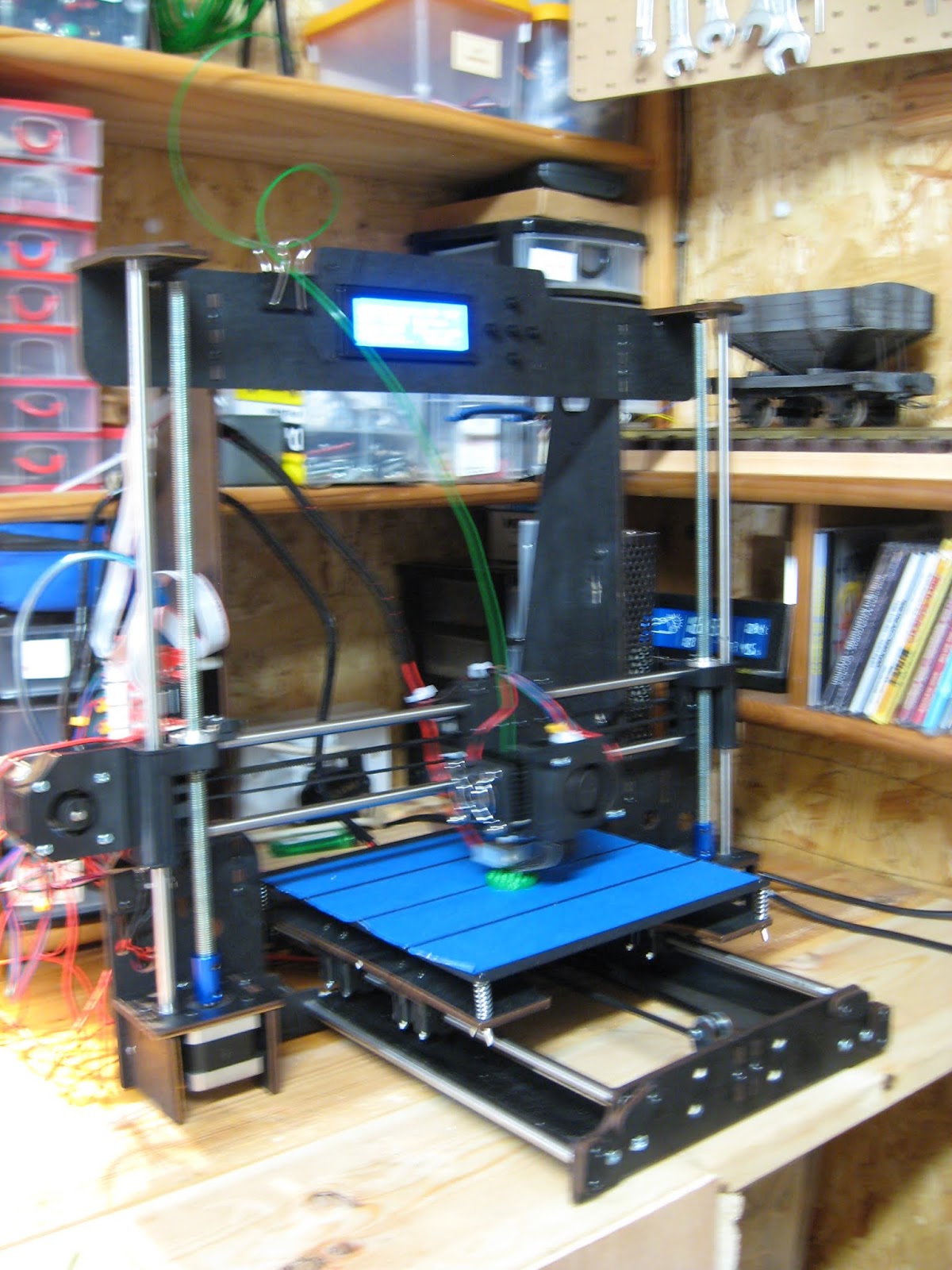
The printer was now more or less ready for action (excuse the rather shaky shot, but it was getting quite late at night when this was taken!).

Before printing can take place, the printer needs to be set up. This is quite a long process but I have found from experience that it is important to make sure everything is properly done if you want decent prints. See Part 2 - Setting up the 3D printer


The lower part of the extruder was carefully removed from its stepper motor (the spring can shoot off across the room!!) using an Allen key.


And then it can be re-assembled using the two screws on the fan assembly to hold it back into place.

The broad-headed screw on the base of the printhead assembly was then unscrewed slightly .......

..... to allow the printhead to be slotted into the bracket on the X-axis sliders.

The broad headed screw was then tightened to hold the printhead in place.

Two M3 x 12 screws were screwed into the back of the X-axis slider bracket......

...... and a loop made at one end of the remaining piece of toothed belt, using a cable tie to fasten it together.

The loop was then passed over one of the screws on the back of the bracket ......

..... threaded around the toothed pulley on the X-axis motor ......

...... around the pulley on the other bracket .........

...... then tensioned and looped around the other screw on the back of the printhead bracket.

As with the other end of the belt, the loop was held in place with a cabe-tie.
NOTE: It is easier to thread the belt over the pulley if the X-axis motor is unscrewed, the belt looped into the space and the motor replaced.
The ducted printhead cooling fan .......

.... was fitted with its 3D printed nozzle .......

...... before being screwed to the front of the printhead carriage with two M3 x 10 screws.

As can be seen, the printer was now taking shape.
The LCD screen
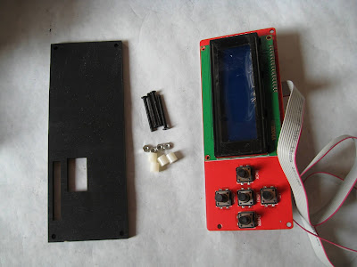
The LCD screen and its mounting plate, together with four M3 x 30 screws and 10mm plastic spacer sleeves were identified.
The screws were passed through the holes in the top chassis plate and the spacers slid on.


...... and its backing plate slotted on.

The nuts were then tightened on the screws to hold the panel into place.

The Power Supply
The power supply was then extracted from its box, together with the relevant leads and mains socket.
Fortunately, the connectors are clearly labelled and so the leads from the socket were attached to the live (red), neutral(black) and earth(yellow) connectors on the left of the supply and the neutral and live output leads connected to the screws on the right - as shown below.

The plastic cover was then slotted over to help prevent electric shocks.

Three M3 x 8 screws and washers were found ......


The power supply was then attached to the panel

There was a square hole beneath the power supply which matched the size of the mains socket, but no holes for the screws.

So, a couple of 3-5mm holes were drilled in the relevant places .......

.... and the socket attached with a couple of M3 x 8 screws and nuts.

The Motherboard
The motherboard, together with four M3 x 20 screws, spacers and nuts were gathered together.
Fortunately, there were some holes in the right places in the left hand chassis upright and so the screws were threaded through and the spaces slotted on .....

..... and the motherboard screwed into place.

I decided to add some washers to avoid putting too much stress on the PCB.

Wiring-up
Although this seemed initially daunting, it turned out to be a lot easier and more logical than I expected.Firstly the two-pin microswitch leads were connected to the sockets on the right of the board. The plugs have lugs which correspond to slots on the sockets and so they can't be connected the worong way round.
The plug from the X-axis miroswitch went in first ........

..... followed by the Y-axis ........

..... and the Z.

Next came the thermistor for the heated printbed (BT) .......

..... followed by the thermistor for the extruder (ET).

Then came the four-pin connectors on the left of the board leading to the motors.
Firstly the lead for the motor on the printhead extruder (E motor).

..... which was then attached to the connector on the motor on the printhead carriage(again, it can only be inserted the right way round).

Then came the right hand Z motor ....

..... which was attached to the motor on the right hand side of the printer as it faces you.

The left-hand Z motor was connected next .....


Next, the Y-axis motor on the back of the printer was connected ......

..... to the board.


..... was connected.

The lead from the fan on the front of the printhead carriage ........


While the lead from the fan on the side of the printhead carriage ......

.... was connected to the left hand socket.

The two output leads from the power supply ..........

...... were connected to the power terminals on the bottom right hand corner of the board - making sure the polarity was correct.

The leads from the heated printbed ...........

....... were then connected to the BED terminals as shown.

And the leads from the hot end of the extruder ........

.... were connected to the remaining terminals.

The printer was now more or less ready for action (excuse the rather shaky shot, but it was getting quite late at night when this was taken!).
Before printing can take place, the printer needs to be set up. This is quite a long process but I have found from experience that it is important to make sure everything is properly done if you want decent prints. See Part 2 - Setting up the 3D printer
Given that I did not have the instructions, the assembly of the printer was fairly straightforward once I understood the function of the various components. It was difficult to decide on the orientation of some parts and had to back-track on several occasions however, dismantling was not difficult and so rectifying some of my mistakes was not to onerous. I suppose that having constructed the printer from its component parts has given me an awareness of the function of each and every part of the printer and I am already beginning to discover ways in which I can now enhance the quality of the prints which it produces by making improvements to the original design (see How I improved my 3D printer - pending)


13 comments:
Hi Rik, I built the same kit (although mine has a black plastic perspex frame, a good upgrade is a couple of relay boards for the printer heat block and the heated bed, takes a lot current away from thre motherboard relays which very borderline power rating devices, the parts are readily available from ebay,
Regards
Paul
Hi, I bought a very similar printer in April and had a lot of fun getting in to 3D printing for my OO gauge railway. I love your solution to the smooth rod swap they did in the box. When I contacted the seller about it they described it is an improvement...
One thing worth checking with recent CTCs, have you tried to print over 4cm in the z axis yet? I hit a firmware issue and I found someone else on reddit with the same issue in the UK at the same time. I found out months later as I'd been printing quite low OO wagons
Hi Paul
I think your perspex frame version will no doubt be stiffer. I find the plywood frame flexes quite a lot which means that any tall components end up with corrugations. I've installed a MOSFET board for the printbed heater but not yet for the printer head. I might do that as well. I've also now got a glass plate for the bed which I've found improves adhesion. My next job is to install a tensioner for the Y axis belt which I've just printed off from Thingiverse
Rik
Hi Anon
Not at all sure about the 'improved' smooth rod system which is why I reinforced it. I've just bought a couple of stainless steel 8mm threaded rods and am planning to install them.
I've not yet printed anything taller than 4cm - I did try a barrel earlier on which did go weird at around 3cm but I just assumed it had somehow come unstuck. I'll try a test print of something tall and thin to see what happens. Did you solve the firmware issue?
Rik
Hi again Rik, I fitted a couple of skate board bearing in housings ( Thingiverse) to steady the 8mm threaded Z axis srews makes a difference when printing tall objects,
Regards
Paul
Hi Paul
Thanks. I found a couple of aluminium 8mm bearings which I've screwed to beneath the top plate to keep the threaded rods from wobbling. I need to stiffen up the frame though as I can see it flexing when the printer is in action
Rik
Not sure what I am doing wrong but my screen just says
Def next the thermometer and the bit on the other side. Seems like the plate at the bottom does on heat. Or the extruder. Its a new build and very lost on why its not pre heating. Any ideas?
It does sound like a problem with the heat settings or connections. Are the bed and print head getting warm at all? If they are it might be the connections to the thermistors, otherwise try checking the connections from the motherboard to the bed and head
Rik
I've had the same problem it's the way the power leads are wired up.if u put the heat bead wires on the + and - then the other 2 on the other side. Then it works fine contact me on my email if u need more help
Hi I had a similar issue with Def so I replaced the thermostat with a screw in one as my little clear cable got covered with pla and replaced the hotend with a better one due to leaking pla .Also I found I had to replace my Y-axis stepper motor with a better one due to skipping after tighting the belt .
Wooden frame just breaks when tighting the screws so I lucky could scan and cut a polycabonate frame as my pocket couldn't afford a metal frame. Enjoyed building it and tinkering with it. But I stopped using the hotbed and found easyware software worked well with the printer. Reduced the jerk in motherboard settings to help stop it shaking as much. Eventually I got great prints. But like you did need extra frame support. Not sure about the metal frame as CTC is bigger the Anet A8.
I'm still having problems with corrugations in the vertical plane. I think it's down to the wooden frame flexing. I've been trying to decide if it's worth investing in a metal frame or just buying a more recent version of the same model. I see it's now possible to buy the clone with a metal frame for a reasonable price.
Im having issues with the firmware does anyone know how to get it
Try - https://github.com/SkyNet3D/anet-board
Post a Comment