
And then, I discovered TinkerCAD.
Not only is TinkerCAD easy to use (it's designed to introduce children to 3D drawing), I have never (as yet) had problems producing drawings which can't be printed. TinkerCAD has limitations which might frustrate those who are used to using 2D CAD packages, but I personally enjoy the challenge of figuring out how to use its tools to produce some of the more awkward shapes inherent in the models I want to create.
Contents
-
Setting-up TinkerCAD
- The wagon side
- The wagon end
- The chassis
- Solebar1
- W-irons
- The axle box
- Leaf springs
- Solebar ironwork
- Solebar 2
- The brake lever
- Brake shoe and hanger
- Brake lever guide
- Frame spacers
- Exporting the designs as .STL or .OBJ files
- Index of techniques
This post will take you through the process of creating an open wagon in 15mm/ft (1:20.3) scale but, of course, the principles could be applied to any scale. I have also tried to cover most of the techniques which are needed to make 3D models of this type, so have indexed the post with links to these techniques which will hopefully make it useful as a reference source.
So, let's get started
Setting Up
Once you have registered with TinkerCAD, you will be presented with
your dashboard. If you are new to TinkerCAD, it will be empty, but eventually
all your designs will be presented on here. Click on
Create new design to get started.

We are now taken to the Workplane, where the designing takes place. As
TinkerCAD has been designed to work with 3D printers, the
workplane represents the printbed on a printer. Like me, you may need
to change it from the default 200mm x 200mm to the dimensions of my
printer.

So, we click on Edit grid

A limited range of printers is provided under the
Presets dropdown list so you might need to type in the
dimensions of your printer's bed - mine is 220mm x 220mm

The wagon side
Planking
Fortunately, most rolling stock is constructed from cuboid shapes and so, our
first job is to click on the Box shape and then click anywhere
on the workplane

We are going to turn this into the topmost plank on the wagon side so, we type
its dimensions into the Shape properties pane-
Length 13mm, Width 168mm and Height 3mm

With shapes like this, it's easier to see them in Plan view. By
clicking on the TOP surface of the
Orientation Cube (in the top left corner of the screen). we can
go straight to the TOP or Plan view. At this stage, you
might want to play around with the cube. By clicking anywhere on it and
dragging it around you can change the 'Camera angle' of the
Workplane. Clicking on various faces or edges gives you views from
those angles.

If you click on the Dotty Box (Fit view) button, the object which is presently highlighted is brought into the
centre of the screen.

The bottommost button on that side of the screen changes the view from
Perspective to Flat view. Particularly useful when looking down
on top of an object.

NOTE: A three-button scroll-wheel mouse is probably the easiest way of controlling the viewpoint.
- Left button - select or drag an object
- Middle button - drag the workplane
- Scroll wheel - zoom in and out
- Right button - change the orientation of the viewpoint
The side of our wagon is constructed from a series of planks, most of which
are the same size and so we can use the
Duplicate and Repeat feature. Once the plank has been
highlighted by clicking on it, the button can be clicked. Although it looks as
if nothing has happened, a copy of the plank has been superimposed directly
over the original plank.

The new plank is now dragged downwards until there is a 1mm gap between it and
the original. NOTE: The position of the plank can be nudged into place by using the
arrow keys on the keyboard.

Once the first plank has been positioned, clicking the
Duplicate and Repeat button another three times will repeat the
process - the three new planks will be automatically positioned 1mm below each
other.

At this stage, you might want to keep things simple and keep all the
planks the same size, but the builders of the Southwold wagon decided the
planks should be of different sizes. Clicking on the black 'handle' on
the lower edge of the second plank and dragging it upwards allows us to resize
it - in this case to 9mm.

The third plank is also resized to 9mm, this time using the shape properties
pane to change its length.

The fourth plank is resized by clicking on the lower black
handle (highlighted in red) and typing 10 into the dimension
measurement on the right hand side of the plank. Hitting return resizes it.

The last plank is resized to 4mm height, using whichever method you fancy.

We now need to move the planks so there is a 1mm gap between them.
NOTE: If you click on a plank and
then hold down the SHIFT key while you drag it, it will drag in
only one direction (in our case upwards). Again, I positioned the planks using
the grid on the workplane.

Once all the planks have been positioned .......

..... we can make sure they are all properly aligned by highlighting them all
(by dragging over all of them) and clicking on the Align Tool. This brings up a series of round handles around the edges and middle of the
highlighted objects. Clicking on any of the handles along the top of the
shapes will align them horizontally.
NOTE: How the Shape Properties pane shows that 5 shapes have
been highlighted.

We now need to unite all the planks. Another Box shape is
brought on to the Workplane and resized to 168mm wide and
49mm long to match the size of the planks.

We also need to reduce its height to 1mm so, we change the viewpoint with the
Orientation Cube (or you can use the right button on a scroll
wheel mouse) and then click on the white handle in the middle of the new shape
.......

.... and drag it downwards until the dimensions shows as 1mm. Alternatively,
we can type 1 into the dimension box.

We will now raise the new shape 1mm above the workplane by clicking on
the cone shaped handle above the middle of the shape and
dragging it upwards by 1mm. This will mean that the divisions between the
planks will show up on both sides of the wagon side.

To ensure it is positioned accurately between the planks, I've selected
the new object and the top plank and then clicked the
Align Tool button. I have then clicked again on the top plank to
show that I want to use this for the alignment. Clicking on the lower middle
round handle aligns the new object horizontally and then clicking on topmost
round handle on the left of the plank aligns the new object vertically.

I've now highlighted all six shapes (the 5 planks and the new backing shape)
by dragging over all of them and then grouped them all together as a
single object by clicking on the Group Tool in the top right of
the screen. The side can now be clicked on anywhere and dragged as a single
whole object.

Hinges and Strapping
The hinge for the wagon side is drawn with yet another box shape, 2mm high.

Another box shape was drawn to make a hinge plate for the base of the vertical
strap.

A 2.5mm diameter x 2mm high cylinder was then drawn, .....

.... the snap grid was turned off, .......

...... so the cylinder could be united with the hinge plate. The cylinder was
overlapped so its centre coincided with the edge of the plate.

The two shapes were then selected and grouped.
NOTE: You can select multiple shapes either by dragging over them or by clicking
one shape and then holding down the SHIFT key on the keyboard
and clicking other shapes. This is particularly effective if the shape you want to select is sitting on top of another which you don't want to select.

The hinge plate was then moved on to the longer strap, 3mm from the curved end
and these two components grouped.

A round roof shape was then reduced in size to 2mm x 4mm x 1mm
high

This was then rotated by 90 degrees.
NOTE: To rotate an object, click
on the relevant double-headed arrow and, keeping the mouse button held down,
move the shape until the desired angle is achieved. Alternatively, click on
the arrow and start dragging, then type in the desired angle into the
dimensions box which pops up. A negative value rotates the object
clockwise.

The hinge was then moved 2mm above the workplane (using the cone shaped
handle) and positioned on the hinge plate below the long strap.

The top of the strap was given a curved end by grouping it with another
cylinder.

The strap was then raised 2mm above the workplane and moved on to the
wagon side, with 1mm of the hinge plate protruding over its edge.
NOTE: As the wagon side is 3mm high, the strap becomes embedded into the side.
Raising it 2mm makes sure it doesn't interfere with the planking divisions on
the underside of the wagon side.

Adding bolt/rivet heads
To represent bolt heads, the domed shape was used. It was resized to 1.5mm diameter.
NOTE: Dragging a black handle on the edge of a shape changes one dimension of the shape, dragging a white handle at the corner of a shape changes two dimensions.
NOTE: Holding down the SHIFT key while dragging one of the white corner
handles maintains the symmetry of the shape - ie the two dimensions are kept
the same size and also the height of the shape changes in proportion.

Once it had been re-sized, the bolt head was raised 4.5mm above the
workplane and positioned on the hinge plate. The bolt head was then
duplicated and moved as shown.

One of the bolt heads was then duplicated and moved into position along the centre line of the lowermost plank.
NOTE: To ensure it was positioned accurately, I used the Ruler Tool (top right of the screen). The red circle on the ruler was positioned over the lower edge of the lowermost plank. Clicking the red circle a few times changes the orientation of the ruler scales until, in this case, the ruler scales were vertical and to the right of the red circle. Clicking the button with lines across it below the red circle changes how shapes are measured - either using their edges or their midpoints. I wanted to measure the position of the midpoint of the bolt head and move it so it was exactly 5.5mm above the lower edge of the plank.
NOTE: You can either drag a shape until the measurement is correct or you can
type the desired measurement into the relevant dimension box

The bolt head was then duplicated and each new bolt head positioned in the
centre of each plank

For the latch plate, a box shape 9mm x 2.5mm x 4.5mm was drawn (and coloured grey so it would show up).

This was then dragged into position just below the topmost plank division,
with 1mm left protruding over the edge.

The whole strap was then grouped, by shift-clicking all the separate parts
because, at this stage, I didn't want to group it with the wagon side (which
would have happened if I'd dragged over the whole assembly).

I then duplicated the strap, ......

..... dragged the duplicate to the opposite end of the wagon side,
mirrored it horizontally by clicking on the mirror tool button and then clicking the horizontal double arrow ......

..... and then aligned it vertically with the first strap.

To make the middle hinge, I firstly duplicated the right hand hinge and
then dragged it off the wagon side.

I ungrouped it completely (by highlighting the whole strap and pressing
the ungroup button a few times).

I then reduced the width of the hinge plate (to 6mm) by dragging the right hand black handle inwards)
.

I deleted the outermost bolt head (by highlighting it and pressing the
delete key on the keyboard). I then duplicated the cylinder on
the left side of the plate and moved the duplicate to the right hand end.

I then grouped all the parts of the middle hinge (and changed its colour to
grey), ......

.... dragged it on to the wagon side and firstly aligned it with the first hinge and then aligned it with the centre of the wagon side.
NOTE: Remember that you can indicate which object you want a shape to align to by
highlighting both shapes, clicking on the align tool button and
then clicking on the shape you want to remain stationary before clicking on
the relevant round aligning handle.

Next came the smaller straps either side of the middle hinge. A 24mm x 2.5mm x
4mm box was drawn.

Both ends were rounded off with cylinders of the appropriate size.

And then the strap was grouped.

To ensure the strap was positioned exactly half way between the hinges, I could have used a ruler, but I decided to use another technique. I resized a new box shape so it fitted between the inside edges of the two hinges (I also coloured it orange so it would show up). I then highlighted the new strap and the new (orange) box and aligned the middle of the strap with the middle of the new box.

The vertical position of the strap was determined by eye so the gap between
the top and bottom of the strap and the nearest plank divisions looked equal.
I then applied bolt heads to the strap.

The strap was then grouped (by shift-clicking all the bolt heads and
the strap and then clicking the group button).

The strap was duplicated and the new strap positioned between the other two
hinges using the same technique as previously.

The wagon side was now finished and so the whole thing was grouped, recoloured and renamed by typing the new name into the title box in the top left corner of the screen.

However, at this stage I realised I'd made a mistake. I had forgotten to raise the smaller straps 1mm above the workplane and so they would bridge the gaps between the planks underneath the wagon side. Rather than re-doing those straps again, I ungrouped the side, drew a large cuboid hole shape and reduced its height to 1mm. This was positioned beneath the two short straps. I then selected the hole shape and the two short straps by shift-clicking.

These three shapes were then grouped together so the bottom 1mm was chopped off the short straps meaning they no longer bridged the gaps between the planks on the underside..
All the components of the wagon side were then selected and the whole thing
regrouped.
To save the finished drawing, I clicked on the TinkerCAD logo in the top left corner of the screen which took me back to the dashboard.
The wagon end
On the dashboard, I right-clicked on the image of the wagon side and selected Duplicate from the pop-up menu

This created a new copy of the wagon side on the workplane. The first
thing I did was ungroup the wagon side.

I then deleted all the straps (by selecting each one and pressing the delete key on the keyboars), except the left hand hinge and reduced the width
of the wagon side to 88mm by dragging in the right hand middle handle (shown
in red).

The headstock was drawn with a new box shape, 88mm x 10mm x 3 mm

This was positioned over the base of the wagon end, so the top of the
headstock was aligned with the top of the bottommost plank.

The headstock was now grouped with the end.

The hinge was ungrouped to all its separate component parts

The latch plate and hinge plate were separated from the vertical strap.

The uppermost bolt head was duplicated and the new bolt head moved down so it
was just below the line of the topmost plank division.

The remaining bolt heads were similarly duplicated and all the bold
heads moved so they were either side of the plank divisions. This was done by
eye, but I could have used the grid on the workplane or a ruler to help
with their positioning.

The hinge plate was reshaped so it was 6.5mm long with just one bolt head at
the rounded end.

This was positioned at the top of the new strap, in line with the second bolt
head.

Another short strap was made by duplicating the modified hinge plate, reversing it (using the mirror tool) and shortening the length of the box section to 4mm.
NOTE: I ungrouped the object before shortening the box section, otherwise
the rounded end would have also been foreshortened.


The bracket was then moved over the strap .....

.... and all the components of the strap grouped. The complete strap was then moved on to the wagon end, leaving the bottom bracket protruding by 2mm.
NOTE: When I came to assemble the parts, I realised this bracket should not
protrude and had to be filed off. At this stage you could adjust the size as
well as the orientation of this bracket to take account of it.

The bracket was then duplicated, mirrored and dragged to the
opposite edge of the wagon end.

The centre straps were then tackled. A new box shape, 55mm x 4mm x 4mm was drawn and superimposed over the end of the wagon. It's position isn't critical at this stage.
NOTE: As with the straps on the side, this strap ought to have been raised 1mm
from the workplane so it doesn't interfere with the planking on the
reverse side of the wagon end. However, this was remedied quickly and easily
afterwards (see below).

Another box shape was then drawn, 55mm x 1.2mm x 7mm. This was positioned as
shown, along the outer edge of the previous strap (though it should have been
raised 1mm above the workplane and reduced in height by 1mm).

The left hand strap was then ungrouped ........
All the bolt heads were then selected (by shift-clicking),
duplicated and the duplicates moved across to the new strap.

The topmost bold head was then duplicated and its duplicate moved to just
below the top of the strap.

All the elements of the strap were then selected by shift-clicking and
grouped.

A ruler was then positioned on the bottom left corner of the wagon end
and the strap moved so it was 25mm from the left hand edge.

The strap was duplicated and the duplicate moved until it was 58mm from
the left edge.

This new strap was then mirrored horizontally.

A hexagon shaped polygon was then moved on to the workplane and resized so its shortest edge was 2mm,
NOTE: Holding SHIFT while dragging one of the corner handles preserves the
shape's symmetry, as with the cylinder.

The hexagon was then raised 2.5mm above the workplane .......


The hexagonal bolt head was then duplicated and its duplicate moved to the
comparable position at the other end of the headstock. It was aligned with the
original to ensure the two were level with each other.

The wagon end was then grouped as a whole and renamed .

At this stage I realised I'd almost forgotten to add the extra pieced required
at the foot of the headstocks to support the bottom of the wagon sides. A box,
2.5mm x 6mm x 3mm was drawn and moved on to the end of the headstock.

It was then duplicated and its duplicate moved to the opposite end of the
headstock.

As with the wagon side, I chopped 1mm off the undersides of the two
middle straps by placing a large 1mm cuboid hole beneath them and then
grouping all three together. This is another feature of TinkerCAD which
I like; the ease with which my mistakes can be remedied.

The whole wagon end was now grouped and saved by returning to the dashboard
(by clicking on the TinkerCAD logo in the top left corner of the
screen).

The chassis
Solebar 1
The beam for the solebar was drawn with a cuboid, 162mm x 10mm x 3mm

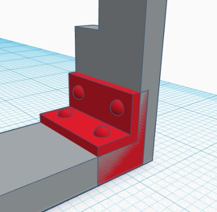
The backing piece for the headstocks was then drawn, 10mm x 2.5mm x 16mm high.

Rebates needed to be made on the upper side of the headstocks to support the wagon sides and so a 20mm x 4mm x 10mm cuboid hole was drawn.

The hole was then raised 13mm above the workplane ......

.... and positioned so its upper edge was in line with the upper edge of the
headstock.

The hole and headstock were then grouped. The headstock was then
positioned over the end of the beam.

The headstock end was then duplicated and moved to the opposite end of the
beam.

The three shapes were then selected, coloured grey and grouped.

The metal brackets attaching the headstock to the solebar beam were then drawn from two box shapes; one 6mm x 10mm x 4mm and the other 2mm x 10mm x 8mm.

1.5mm diameter domed bolt heads were then added to the horizontal part of the bracket
.......

...... and then they were duplicated, raised up until they were 9mm above the
workplane and then rotated through 90 degrees.

They were then moved across on to the vertical face of the bracket.

The components of the bracket were then grouped and the bracket duplicated and
mirrored.

The brackets were then positioned at the ends of the beam, so that they were 1mm proud of the beam and the headstock.
NOTE: I tend to over engineer components to ensure that there are no unexpected
gaps between them when they are joined together.
The brackets were then grouped with the beam and headstock assembly.

The W-Irons
The two components for one half of a W-iron were then drawn - one 25mm x 4mm x
2mm and the other 25mm x 2mm x 2mm.

Because I wanted to rotate the narrower piece about one end, I doubled its length to 50mm and then superimposed it over the other part so its centre was in line with the edge of the wider piece. I then positioned the centre mark of the narrower piece so it was 4mm above the base of the wider piece. This would ensure it was in the correct position (roughly 3mm above the base) after it had been rotated

I could have measured the angle on the drawing of the wagon to determine how
much to rotate it, but instead decided to use the width of the top of the
W-iron as my guide. It needed to be 15mm and so I drew a cuboid hole 15mm wide
(the width and height were immaterial) and positioned it along the top edge of
the wider part to act as a marker.

I then rotated the narrower part until its edge was in line with the end of
the marker piece.

The marker piece was then moved up so it was in line with the top of the wider
part and another box hole was drawn over the bottom end of the larger part and
all the shapes were then grouped.

The iron was then duplicated and mirrored ....

..... and the new iron moved so it was 8.5mm away from and back to back with
the original.

An 18.5mm x 1.5mm x 2.5mm cross member was then drawn .....

..... and moved so it spanned the gap between the two irons.

Its ends were rounded off with a couple of cylinders ......

..... and all three shapes selected and grouped.

The two irons were then grouped to form the W-iron and then it was selected
with the cross member so the cross member could be accurately aligned with the
centre of the W-iron

The axle box
A 9.5mm x 9.5mm x 2.5mm box shape was then drawn .......

... and positioned as shown in the centre of the W-iron, leaving a 1mm gap
between it and the cross member.

A 9.5mm x 7.4mm x 8.5mm high box shape ......

..... with 2.5mm radiused edges ........

.... was then centred over the previous box shape.

A 2mm radiused 1.5mm x 9.5mm x 9mm box ......


..... was then positioned along the centre lines of the previous box shape.
Leaf springs
I've found that the Ring shape is good for representing leaf springs as it has an oval profile which can be widened for stiffer springs.
A ring shape was positioned over the W-iron and its size adjusted until
it looked about right when compared to the wagon drawing.

A box hole shape was superimposed over the top half of the ring, and
the two selected (by shift-clicking) ....

.... and grouped.

Another ring shape was then positioned below the first leaf and its size
adjusted until it fitted.

The box hole shapes were then positioned around the second ring shape as show
and then all four shapes selected by shift-clicking and grouped,
thereby trimming the second leaf to the desired shape.

This new leaf was then duplicated and the duplicate moved down below
the second leaf.

Two box hole shapes were then positioned over the ends of the third leaf and
all three shapes grouped.

A box shape was then reduced in size to fit over the middle of the leaves
...

.... and a round roof shape rotated through 90 degrees and adjusted in size
until it fitted behind the leaves and above the axle box.

All the component parts of the W-iron were then selected (by dragging across
them), coloured light grey and grouped together.

A 3.5mm diameter, 5mm tall cylindrical hole shape ........

..... was then positioned in the centre of the underside of the axle box (the axle box assembly was flipped upside down using the Orientation Cube in the top left corner of the screen). The hole was then grouped with the W-iron assembly to make a suitable hole for the journals on the wheel-sets I will be using.
NOTE: I made the hole slightly larger than the 3mm journals on my
Bachmann wheels, you might be using different wheelsets or maybe want
to include some brass top hat bearings and so may need to adjust the size(s)
of the holes you make.

I now positioned a ruler over the end of the solebar beam and clicked the centre of the ruler axes until the ruler scales were pointing upwards and to the right.
NOTE: If you select the solebar beam you can roughly position the ruler beside
it, and then type zeros into the two offset dimension boxes (circled in red below) to ensure it is
perfectly aligned with the corner of the beam

As I wanted to use the centre of the wheels to position the W-irons, I clicked
on the button (a circle with three lines inside) to get the ruler to measure
to the midpoint of selected shapes.

I then moved the w-iron so it was below the solebar beam and, with it
selected, typed 40.5 into the
dimension box showing the distance of the centre of the W-iron
from the end of the solebar beam.

To connect the leaf springs to the solebar beam, I draw an oval cylinder, 4mm
x 6mm x 3.8mm, ....

..... and moved it over the top of the leaf spring. I then added a couple of
domed rivet heads.

The oval bracket and rivet heads were then duplicated and the duplicate moved
to the other end of the leaf spring.

The W-iron and leaf spring brackets were then grouped together, duplicated and
the second W-iron assembly moved until it was exactly 40.5mm from the other
end of the solebar beam

The beam and W-irons were then grouped together.

Solebar Ironwork
To make the ironwork on the solebar beam, I started off with a 2mm x 5mm x 4mm
high box shape.

Its ends were rounded off with a couple of cylinders ....

.... and the whole thing grouped.

To ensure the angle on this iron matched that of the diagonal section of the
W-iron, I placed it alongside the diagonal and then rotated it until it was
parallel.

The new piece of ironwork was then positioned on the beam in line with the
diagonal of the W-iron.

Domed bolt heads were applied in the usual way, .......

..... and then the ironwork was grouped, duplicated, moved and mirrored to sit
above the opposite diagonal.

The two parts were then selected (by shift-clicking), duplicated and moved
across to sit above the other W-iron.

To make the curved pieces of ironwork, a 4mm high tube shape was placed above the centre of one of the W-irons and its dimensions altered until it matched the verticals on the W-iron.
NOTE: The wall thickness of the tube was adjusted to
4mm in the shape properties window.

The lower half of the tube was then lopped off, using a box hole shape.

The ends of the remaining half of the tube were rounded off with cylinders and
the whole piece was grouped together.

One of the bolt heads from the diagonal ironwork piece (which has been
ungrouped) was duplicated four times and distributed around the curved
ironwork piece.

The curved ironwork section was then grouped, duplicated and moved across to
sit above the other W-iron.

The whole solebar assembly was then highlighted and grouped together,
its name was changed and it was saved (by clicking on the
TinkerCAD logo in the top left corner of the screen).

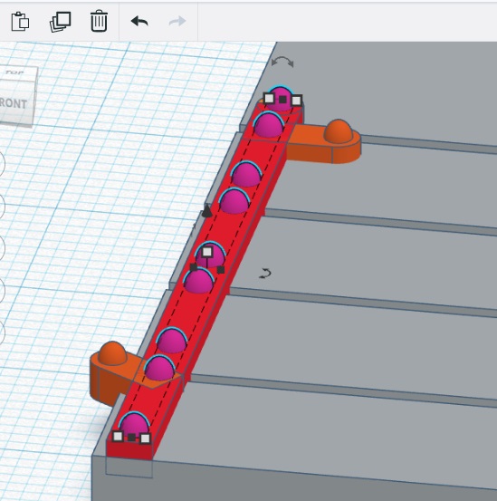
The brake lever
A copy of the solebar was made (by right clicking on the solebar image in the
dashboard and selecting Duplicate)

A round roof shape was resized to 6mm x 3mm x 6mm tall ......

..... rotated through 90 degrees and then dropped down on to the workplane (by
pressing the D key on the keyboard)

It was then dragged to below the solebar beam, adjacent to the leaf spring
hanger on the left hand W-iron.

A trapezoid shape (page 10 of the
Shape Generators tab) was then resized to 3mm Base Width, 1.4mm
Top Width, 90mm Height and 8mm Thickness using the
Shape Properties Window.

It was then rotated through 90 degrees vertically ......

.... and -88 degrees horizontally and then dropped down to the
workplane (by pressing the D key)

It was then dragged so its fat end coincided with the round bracket below the
solebar beam, and its end rounded off with a cylinder shape.

To add an angle to the upper surface of the brake lever a
box hole shape was resized to 20mm x 90mm x 20mm

This was then raised 4.5mm above the workplane (using the cone shaped
handle)


The trapezoidal brake lever and the box hole shape were then grouped.
NOTE: I decided not to slope the underside of the brake lever. This makes it
easier to print and also gives it more strength. Under normal running
conditions, its thickness will be hardly noticeable.

The brake lever guide was tackled next, with a 2mm x 20mm x 6mm box shape,
positioned between the end of the brake lever and the leaf spring hanger.

Its lower end was rounded off with a 2mm thick cylinder shape suitably
rotated.

The holes in the guide were made with a 1mm diameter x 7mm high cylindrical
hole shape, .....
.... centred in the middle of the guide, .....

... duplicated, moved 2.4mm .......

..... and repeated three more times (by clicking the
Duplicate button 3 more times)

The brake lever assembly was then highlighted and grouped with the rest of the
solebar, renamed and saved (by clicking on the TinkerCAD logo).

Brake shoe and hanger
The brake shoe was created from a 14mm x 4mm x 2.4mm box shape.

Because I will be using 32mm diameter wheels, a 32mm diameter cylindrical hole
shape was superimposed over the shoe and grouped with it to make the
curved surface of the shoe.

A 1.5mm diameter x 3mm high cylinder was positioned in the centre of the
shoe.

A 2mm x 17mm x 1.5mm box shape was then rotated through 10 degrees and
joined to the shoe at its mid point

Its end was rounded off with a 2mm diameter cylinder.

Another 25mm x 2.6mm x 2mm box shape was then created .......

.... and given a rounded end with a 2.5mm diameter cylinder.

1mm diameter holes were drilled in the lever attached to the shoe .....
..... by grouping all the parts together.

The brake actuating arm was then superimposed over the brake lever and rotated
through 12 degrees.

A 5mm x 20mm x 5mm mounting block was then positioned over the top of the
actuating arm ....

..... and a 20mm x 2mm x 4mm hanger placed between the top of the brake shoe
and the mounting plate.

The everything was highlighted and grouped together (and coloured grey).

The brake shoe assembly was then renamed and saved by returning to the
dashboard (by clicking on the TinkerCAD logo.).

Spacers
Spacers to ensure the solebars are the correct distance apart were created from a 10mm x 60mm x 3mm box shape
NOTE: This is for a 45mm gauge wagon. Spacers for a 32mm gauge wagon would be
44mm wide (assuming you are using standard wheelsets).
I decided the spacer should be indented with lettering and so the
Text shape was selected from the toolbox and "45mm spacer" typed into the text box in the Shape Properties window. The font was
also changed to 'Sans' and the height of the letters changed to 6mm

The lettering was raised up 2mm and positioned on the spacer shape

The lettering was then centred using the align tool.The lettering was then
turned into a hole (by clicking on the hole button in the Shape Properties
window.

|
The spacer was then renamed and saved by returning to the dashboard via the
TinkerCAD logo in the top left of the screen.

|
Exporting the parts as .STL files
Before they can be printed, all the parts need to be exported at .STL or .OBJ files.
From the Dashboard, click the Tinker This button on the relevant part.

Once the workplane screen has loaded, then click on the
Export button in the top right of the screen

In the pop-up window, click .STL (or one of the other buttons if
you prefer a different type of file) and then follow the usual dialog boxes to
save your drawing in a folder where you can find it again.

I am assuming from this point onwards you are familiar with how to use a slicer program appropriate for your printer and can adjust the settings to produce 3D printed parts ready for assembly into a Southwold Railway open wagon.
For more information on how I printed and constructed my wagon see How I printed and assembled a Southwold Railway Open Wagon
Index of techniques
- Aligning shapes
- Changing the viewpoint
- Deleting a shape
- Dimensions
- Changing dimensions using a shape's properties
- Changing dimensions by dragging handles
- Changing dimensions using dimension boxes
- Keeping a shape's symmetry when changing dimensions
- Duplicating shapes
- Duplicating a design
- Exporting a shape as a .STL or .OBJ file
- Grouping shapes
- Holes
- Creating holes in shapes
- Creating holes in shapes
- Trimming a shape with a hole
- Making a rebate in a shape using a hole
- Creating a sloping upper surface with a hole
- Raising a shape above the workplane with a hole
- Indenting lettering into a shape
- Mirroring shapes
- Radiusing or rounding off the edges of a shape
- Raising a shape above the workplane
- Renaming a shape
- Rotating shapes
- Rulers
- Inserting a ruler
- Aligning a ruler to a shape
- Moving a shape into position with a ruler
- Measuring to the midpoint of a shape
- Using a shape to measure instead of a ruler
- Selecting or highlighting shapes
- Snap Grid

8 comments:
Rik,
one can't thank you enough for those extensive tutorials, I'm learning so much just by reading and imagine applying it to my own projects.
Would you mind sharing some of your printer settings? I'm especially interested in layer thickness and printing speed, they seem to have a massive effect on how detailed a print job can be.
Best regards, stay well!
Frédéric
Hi Frédéric
My general layer setting is 0.1mm and I've just reset the top and bottom layers to 1.2mm as I was getting some pillowing on the top layer.
The print speed on my cheap Anet A8 is 40mm/sec and on my better quality printer is 60mm/sec (with the outer walls printed at half those speeds on both printers).
Hope that's helpful
Rik
Hi Rik,
What a brilliant tutorial you have done. Although it's a bit beyond me at the moment, I will print out the tutorial and have a go with my MacBook at some point soon with the Tinkercad app I have already loaded.
It's purely to try and get to grips with the technology that is used to draw a product. I am thinking once I have done some thing like this wagon, it would make it a little bit easier to make other things, HOPEFULLY..lol.
Hopefully, it will all make sense when you start using TinkerCAD for a purpose, Rod. I've tried to introduce each new tool or technique as the need for it arises. I've also included a contents list at the start and an index of techniques at the end. So, you can either work your way through from the start and build a wagon like mine (or adapt it to suit your own ideas), or you can just dive in and then use the contents list or the index when you're not sure what to do next.
Hi
Is it possible to print this tutorial out in word.
Thanks
Yes. If you right-click, then "Select All". Right-click again and "Copy". Then open a blank document in Word and right-click and "Paste - keeping original formatting"
I warn you, it's 105 pages of A4 - but you can delete the last ten pages of blurb.
Rik
Wow! Excellent Tutorial!
I have been looking for details on how to model such wagons and this is perfect! Will be trying to implement this in 1:160 scale!
CG
I wish you well! Will you be using a resin printer? I assume you'll need it to produce the fine details in that scale.
Post a Comment