I have always admired the Bachmann Lyn locomotive but never been able to justify the expense of buying one. So, when one came my way at a reasonable price, I couldn't resist - and the fact it coincided with a significant birthday increased the incentive.
Eventually, I am going to convert it into something more appropriate for a three foot narrow gauge railway. Lyn is a model of a Baldwin locomotive which ran on the 1'11½" Lynton and Barnstaple Railway and is constructed to the unique scale of 13.8mm : 1ft - which means it's a tad too small for my 15mm : 1ft railway. I am presently studying Irish 4-4-0T locos to see if I can find one with driving wheels which match those on the Lyn - but all that is in the future. Converting the Lyn to battery r/c is a stop-gap measure as a way of familiarising myself with its construction and possibilities for later re-conversion.
The first stage of the conversion process was disassembly
Disassembly
The first job was to separate the body from the chassis. The two small domes were removed ....... to reveal the screws holding the body on to the motor block.
The two screws were then removed.
The front pony truck was then removed by unscrewing its pivot screw ......
.... to give access to the screw holding the smokebox to the chassis.
This was then unscrewed so the body could be removed.
The cab was then removed by depressing the four clips which hold it in place.
The pipe on the front of the cab was prised off which a pair of pliers ......
The cab was then removed from the footplate.
I decided to removed the side tanks as I wanted to see how much space was available. The four screws holding the tanks in place were unscrewed ......
.... and the tanks removed. Although there is some space inside the tanks, I decided not to make use of it as I wanted to retain the weights for adhesion.
Rewiring the front lamp with red and white LEDs
At this stage I decided to remove the front lamp. This simply slid forwards to release the catches holding it in place.
The upper part of the lamp was prised off with the blade of a craft knife, revealing the grain of wheat bulb inside. This was removed ......
...... and a 3mm red and 3mm warm white had their negative legs soldered together and grey and red wires soldered to the +ve legs. If I had had a 3mm red/white LED available, I would have used it but decided to make my own as I found I could just squeeze them inside the lamp.
Heatshrink tubing was applied to the legs ......
.... and the LEDs fitted into the lamp housing after the hole in its base had been opened out.
The lamp cover was glued into place .....
.... and the lamp slotted back into its housing ......
..... and the smokebox door refitted.
The wires were then threaded through 3mm holes drilled in the webs inside the boiler .....
..... and then fed through a hole in the firebox and on into the cab.
Removing the track pickup contacts
Although it's not essential, I decided to remove all the track power pickups. The pickups on the rear bogie were removed first, by unscrewing the covers over the wires and the contacts for the axle.
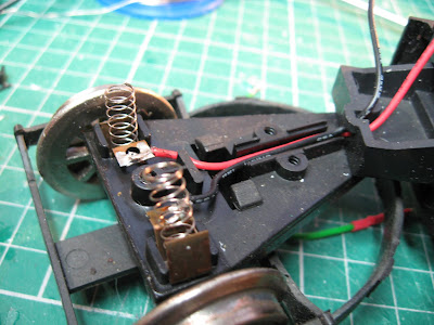
The contacts, springs and wires were removed and the cover over the axle replaced.
The three screws over the covers for the wires and axle on the front pony truck were removed.
The wires, springs and contacts were then removed .......
.... and the axle cover replaced.
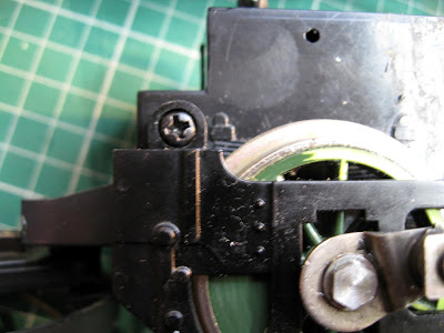
Again, it wasn't essential, but I decided to remove the contacts on the driving wheels. The bracket holding the motion in place was removed by unscrewing the screw holding it in place. This allowed the cylinders to be removed.
Then the bolts holding the wheels on the axles were removed with a 50mm spanner.
This allowed the fly cranks to be removed.
The screws holding the outside frames were then removed.
The motor block was now ready to be dismantled.
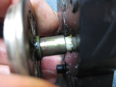
The wheels on the side of the motor block with the four screw holes were prised off. They are a push-fit on the gears.
The motor, gears and contact strips were now visible. The motor was removed from its housing - again it is just a push-fit.
The brass strips over the wheel contacts could then be removed. Once more these are just a push-fit.
The sheaths, springs and carbon brushes could then be removed.
The vertical contract strips were also removed.
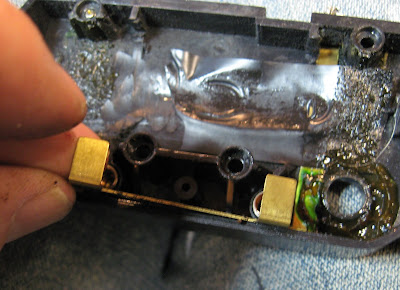
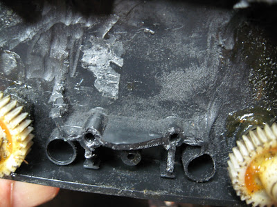
The same process was repeated on the other side of the motor block shell. I was able to inspect the brackets into which the self tapping screws screwed. I had noticed that one of the lower screws was loose when dismantling the motor block clamshell. It was clear that the plastic had sheared. I was in two minds as to whether I should drill through the brackets and replace the self-tappers with bolts and nuts, but I didn't have any bolts long enough. I figured there was sufficient plastic left to allow a longer self-tapping screw to bite. However, before reconverting the loco, I will replace all the self tappers with bolts and nuts. The plastic is clearly too brittle.
The motor block given a good clean-up and then reassembled with fresh grease on the gears. Quartering the motion was actually quite easy as the wheels and flycranks are held in place on square-shaped axles. However, after initially re-assembling the motor block I noticed the fly-cranks weren't opposite the weights on the driving wheels and so had to remedy this.
Wiring up for battery radio control
Two holes, one 4.5mm diameter and the other 8mm diameter were drilled in the floor of the cab to one side, for the single pole two way switch and the DC charge socket.
These were then wired-up (see wiring diagram)
A Deltang Rx65c was acquired from Micron Radio Control .......
The grey and red leads from the headlamp LED were soldered to P1 (auto front light) and P2 (auto rear light) and a green wire soldered to P5 for the whistle trigger on the soundcard (when the bind button is pressed - Ch5). Brown wires were soldered to the Motor outputs and red and black wires attached to the + and - inputs.
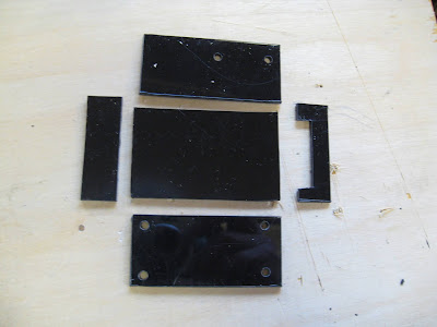
A box was constructed to hold the various components - 45mm x 65mm x 30mm - from 2mm thick black plasticard.
One end was left off the end of the box to allow for the wiring.
The MyLocoSound steam soundcard was wired-up (see wiring diagram) and a small speaker wired-in.
The Deltang receiver was attached to one side with a cable tie and .....
the whole assembly was attached to the cab floor with another cable tie.
Circuit diagram
Reassembly and testing
The body, pony truck and rear bogie were then attached to the motor block and the domes replaced. The model was then given some extensive testing out in the garden.
There were a couple of problems which I encountered. Firstly, the model was initially a bit stiff until the grease worked its way into the mechanism. I also had to ease the motion by bending it slightly to avoid binding. I also discovered that the cow catchers were gathering snow beneath the loco as it negotiated the track and causing it to grind to a halt every so often. You may notice in the reverse run on the video, the cow catchers have been removed which improved running no end.
If I was going to keep the loco in its present form, I would find a way of attaching couplings to the pony truck and rear bogie. The loco is quite long and the outswing on curves is quite dramatic. Again, you will notice on the video that the chain linking the loco to the first track is quite long - it had to be otherwise the loco kept pulling the wagon off the rails each time it negotiated one of my sharp curves.
As indicated above. I intend to remodel the loco - probably based on one of the 4-4-0T locos which ran on the Irish narrow gauge railway system - though I am struggling to find a prototype which matches the driving wheel size (2' 6" in 15mm scale) and wheelbase (4' 7" in 15mm scale).
I may have to make a few compromises and construct a derivative model based on several prototypes rather than a scale model.













2 comments:
Hallo, why you User two charging Socket?
No, only one charge socket
Post a Comment