Monday, April 21, 2014

How I improved the mechanism for my IP Engineering Jessie diesel


A while back I constructed an early IP Engineering 'Jessie' diesel loco kit (see How I constructed an IP Engineering diesel) but very quickly found that the nylon gears in its gearbox were insufficient for the loads my railway places on it.

A replacement IP Engineering gearbox very quickly wore out and so a kindly fellow modeller constructed a bespoke gearbox for me based around some brass 00 loco gears.

This lasted me a season, and so when I dusted off the loco to resume service this year, I found this gearbox too had succumbed to the dreaded wear. Having had a great deal of success with commercial loco blocks on my other track- and battery-powered models, I cast about for a suitable block to instal underneath Jessie (or Wynford as she is known on my railway). The most appropriate I could find was a USA Trains short wheelbase motor bogie, but after making several enquiries I discovered this is now no longer available. Whereas the wheelbase of Jessie was 60mm, the nearest I could find to this with extended axles for the fly-cranks was the USAt medium power bogie with a wheelbase of 84mm. On downloading the datasheet for this motor block from the g-bits website, I discovered it would fit beneath the chassis, though of course I would have to extend its wheelbase (and also source some longer coupling rods).

 First of all, I had to adapt the motor bogie for battery power, by removing the track pick-ups. The base of the block was removed .....

.. and the skates unclipped.

Two screws holding the plates covering the wipers for the axles were then removed.....

...... and the wiring snipped from the motor contacts.

The block was reassembled. The coupling rods were removed from the loco, by prising open the spring-clips.....

...... and then the grub-screws holding the fly-cranks were unscrewed.

The sides of the chassis could then be unscrewed........

....... and the old motor and mechanism extracted.

The motor-block was then test-fitted and the position of the new axle holes marked for drilling. The rear axle holes were retained as these provided clearance fro the switches and charging socket. I also decided to remove the bushes from the axle holes as these were redundant and also reduced the working length of exposed extended axle for the fly-cranks.

To hold the block in place, a U-shaped bracket was fashioned from brass strip and fixed to the chassis. The ends of the bracket passed through the slots for the skates on either side of the block and were bent over to hold the block in place. The fly-cranks were then screwed on to the extended axles .......

....... and the loco was test-run.
 I had to adjust the fly-cranks a few times to prevent them from binding, but the mechanism proved to be a lot smoother (and quieter) than its three predecessors.

I was unable to track down a source of coupling rods with 84mm centres and so these were marked out on a piece of 64thou brass strip and filed to shape in a vice.

The cranks required a little adjustment to ensure they were properly quartered and some more test-running was undertaken with a full load of tipplers up the steepest gradients and around the sharpest curves.

She tackled the gradients without hesitation but there is a noticeable slowing when she negotiates the R1 curves which still exist on my railway. This is presumably a side effect of the longer wheelbase. I am intending to remove all the R1 curves over time and so this is something I can learn to live with.

The redundant holes in the sides of the chassis were filled with epoxy filler, then filed and sanded smooth ........

...... before the chassis was given a coat of matt black acrylic (ordinary black mixed with talcum powder).


The chassis was then weathered with a mix of brown and black weathering powders and given a light coating of matt varnish to seal them.

The loco was then tested once more.


There is still some detailing to be completed: repositioning the sanders in front of the front wheels and adding a few details, such as pipework, name- and number-plates and some clutter to the cab. I think I might try making the exhaust pipe vertical - though as this is a whitemetal casting I and concerned I might do more harm than good.


Tuesday, April 01, 2014

How I created some flat wagons (with loads)

I have three types of flat wagons on my railway; one type adapted from the Hartland Locomotive Works (HLW) Mini Series of wagons, one type which is simply a repaint of the LGB stake wagon and one made from an Atropos kit for an Admiralty wagon.

Adapting an HLW wagon

This is a fairly straightforward bash. HLW wagons can be bought quite cheaply from various suppliers including Back2Bay6 - mine cost between £10 and £15. The lower bodies for the tank wagon and the tippler wagon are moulded with planking and so lend themselves readily to modification into flat wagons. The kit for the chassis comprises very few parts which mostly slot together.

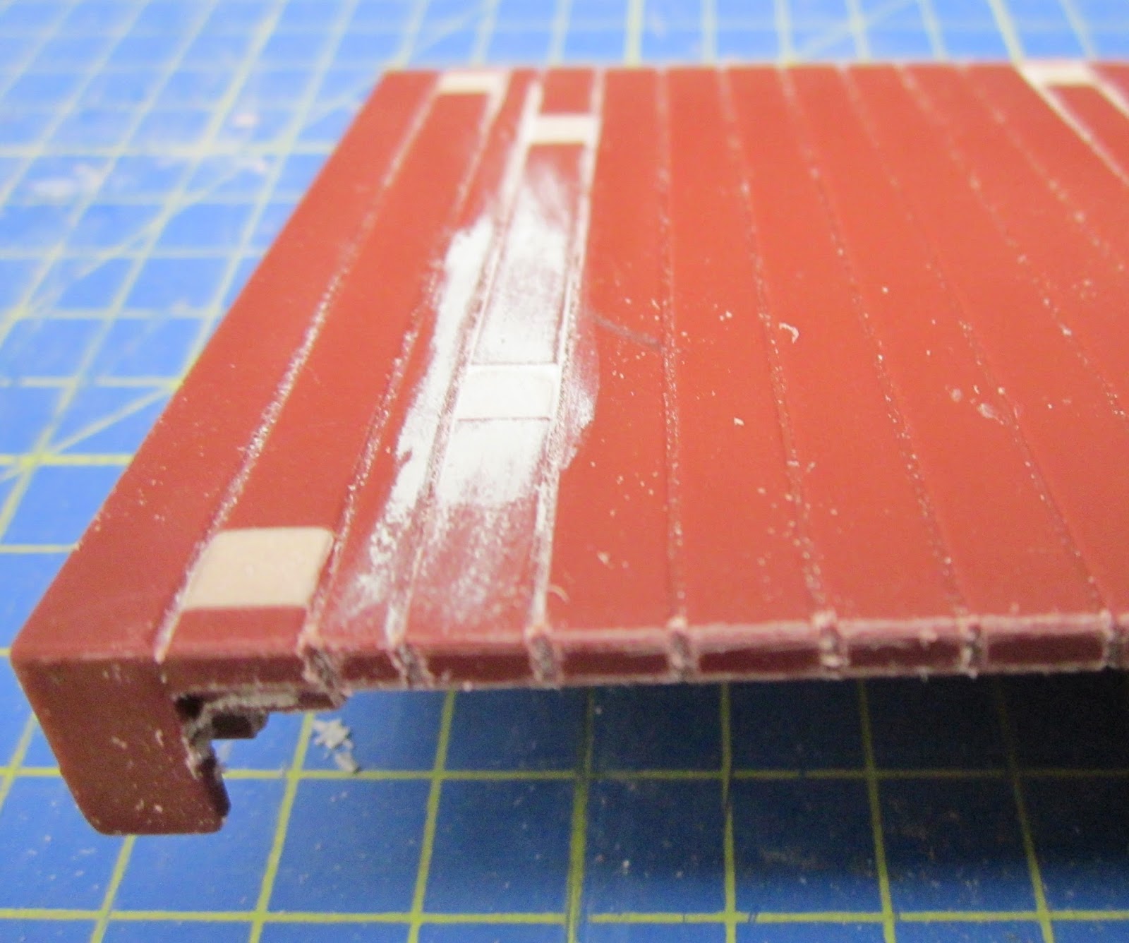
The first task was to fill the holes. On this occasion, I used car filler as that is what I had to hand, but any type of resin or filler will do the job. Firstly, I taped over the holes on the upper surface with masking tape.

Filler was then poured into the holes on the underside. 

With car filler, I needed to puddle the filler down into the holes with a straightened out paper-clip to ensure there were no air-bubbles.

Once the filler had hardened, I scraped or filed off any excess and in places tidied up the filling with model putty. At the same time, I filed the edges of the body to extend the planking down the sides.

The body was then ready for the next stage.

Two pieces of 6mm square section styrene (eg Plastruct) were cut to the width of the body. On this occasion, I did not have any square section to hand and so I added 1mm thick plasticard to two sides of some 5mm square tube.

These cross-members were then superglued to the ends of the body.

The mould-lines at the ends of the body were then smoothed down with a file and the ends of the tube were plugged with filler and also filed smooth.

The body was then given a couple of coats of Halfords' grey primer from an aerosol rattle can.

While the paint was drying, I stripped some insulation from a piece of twin and earth electrical cable.

A short length was then wound tightly around the stem of a small Philips head screwdriver.

 The loops were then sawn through with a razor-saw and squashed flat with pliers to form rings.

 Eyelets were then formed from 1.5mm lengths of wire....

 The rings were then threaded on to the eyelets and the closed shut with pliers.

 These were then given a light coat of matt black primer. 

I usually find that giving a model a couple of coats of primer exposes any imperfections in the bodywork, and this was the case with this model. White Putty filler was applied to the various dints and crevices .......
 

 .... and then smoothed off with a file and fine emery paper ........

 ....... before being given another couple of coats of grey primer.

Four 1.2mm holes were drilled in the ends of the upper sides of cross-members,.......

........ and the eyelets and rings inserted with a dab of superglue to hold them in place.

 The solebars and couplings were then added to the body, as per the instructions and the wheels. I use large diameter Bachmann metal wheels to give the wagon more weight and to improve its smooth running.

 The wagon was now ready for service (although in need of weathering - see How I weather my wagons)

 One flat wagon was given a load of some farm machinery (Brittains' models). Although these are under-scale, once painted and clustered together, they look suitably agricultural. The items were glued (with Evostik) to a sheet of 2mm thick plywood, scribed to match the planking on the wagon. The ply was made a tight fit in between the cross members and so the wagon can run down the line loaded and return empty (See Managing freight on the railway).

Another flat wagon acts as a match wagon for the mobile crane (scratchbuilt on another HLW flat wagon chassis - see How I constructed a mobile crane).

The tools and loco jack are whitemetal castings from various sources and the toolbox is made from a piece of balsa with paper-clip wire handles. More clutter will be added as time and maybe finances permit.

At present the third flat wagon is unladen. When I see a suitable lineside model in roughly the right scale (eg a stationary engine or a piece equipment for the copper mine), it will be mounted on a piece of ply for transportation down the line.

LGB Stake Wagons

At present, there are four of these on the railway. Three are used to carry timber to and from the timber yard at Peckforton.

Their loads are plastic Bachmann (?) logs, purchased through eBay. They have been lightly weathered with Humbrol matt acrylic aerosol sprays (Dark Earth (29) and Sand (63)) to make them less shiny. Four to six logs were glued together as a unit with Evostik and fine chain then glued across and left dangling at the ends. This enables the logs to be removed as a unit to enable the wagons to travel in unloaded condition down the line. 

Another stake wagon has a tractor load. 

After searching in vain for a model tractor of the right period (ie early 1930s) in the right scale, I happened across some resin money boxes which vaguely resembled early tractors in more or less the right dimensions. One of these was purchased. the slot filled in with resin and mounted on piece of 2mm plywood the same size as the wagon. Pegs were attached to the underside of the ply to slot into the brackets for the stakes - thus enabling the wagon to return empty once the tractor has been delivered to its destination.

Atropos Admiralty Wagon

This was actually purchased as part of a job-lot of wagons on eBay and initially, I considered selling it on. However, I was so impressed by the quality of the kit and the finish which the builder had achieved I decided to find a use for it on my railway. It is now attached to the first passenger train of the day to transport milk churns.

I needed quite a large number of churns, not only to load on to the wagon but also as part of lineside detailing around the railway and decided that the expense of buying resin cast models was going to be prohibitive - so I made my own (see How I constructed some milk churns).

I found the flanges on the wagon were too narrow for the LGB pointwork which meant that the wagon derailed regularly whenever it negotiated the curve of a point (turnout). The wheels were replaced with Bachmann small diameter metal wheels and LGB style couplings were added..

This wagon needs some weathering but has proven itself to be an important part of the railway's workings.

I am not planning to construct any more flat wagons. I feel I now have sufficient to meet the freight needs of my railway. I did consider making one into a one-plank wagon, but am quite satisfied with the appearance of the wagons as they exist.


Friday, March 28, 2014

Peckforton Light Railway - a guided tour

I've realised that it's a while since I provided readers with a guided tour of the railway and, given the number of posts on the blog, it's probably about time I provided a new overview. I will continue to update this post to reflect new developments as and when they occur.

The setting for the railway

 The hypothetical setting for the railway is beside the Peckforton Hills in Cheshire. Over the years, copper has been extracted from mines along these hills, though never in sufficient quantities to make it financially viable. In my imagined history of the area, a rich seam of copper was struck which spawned the need for a light railway. (see also Copper Mining at Bickerton and A brief history of the railway and its locality).
Tipper wagons being loaded from the minimum gauge railway at the copper mine

The route for the railway

 The railway supposedly runs from the (now closed) station at Beeston & Tarporley on the Chester to Crewe Railway, past Beeston Castle, through the villages of Beeston, Peckforton and Bulkeley to the village of Bickerton. A branch between Peckforton and Bickerton leads to the copper mines at the foot of the Peckforton Hills. (see The hypothetical line and A trip along the railway).
Aerial view of the supposed route of the railway as it runs below Beeston Castle

Traffic on the railway

The period in which the railway has been modelled is 1932 - a difficult time for minor railways in the UK. In my imagined history of the railway, it has continued to survive whilst others perished because there was a continuing need for its services. In addition to daily trains of copper ore and spoil, there was a demand for the transportation of agricultural commodities such as feed, machinery, and livestock to the thriving cattle market at Beeston.
0-6-2T Manning Wardle Loco No.4 Bulkeley departs Beeston market with the Down pick-up goods
 In addition there was the export of fruit, cheese and milk. There was also a need to transport domestic supplies such as coal, fuel oil, groceries and building materials. The local estate also had a thriving trade in the production of pit props for the mining industry and sand and high quality red sandstone from local quarries.
Loaded copper ore train about to depart the mine sidings
 Owing to its proximity to Liverpool, Manchester and Chester, the railway also benefited from tourist excursions to Beeston Castle and the Peckforton Hills where visitors could sample and bathe in the spa waters. And, of course, there was a very supportive local community whose affection for their railway provided a steady income during the winter months. See  A Typical Operating Session
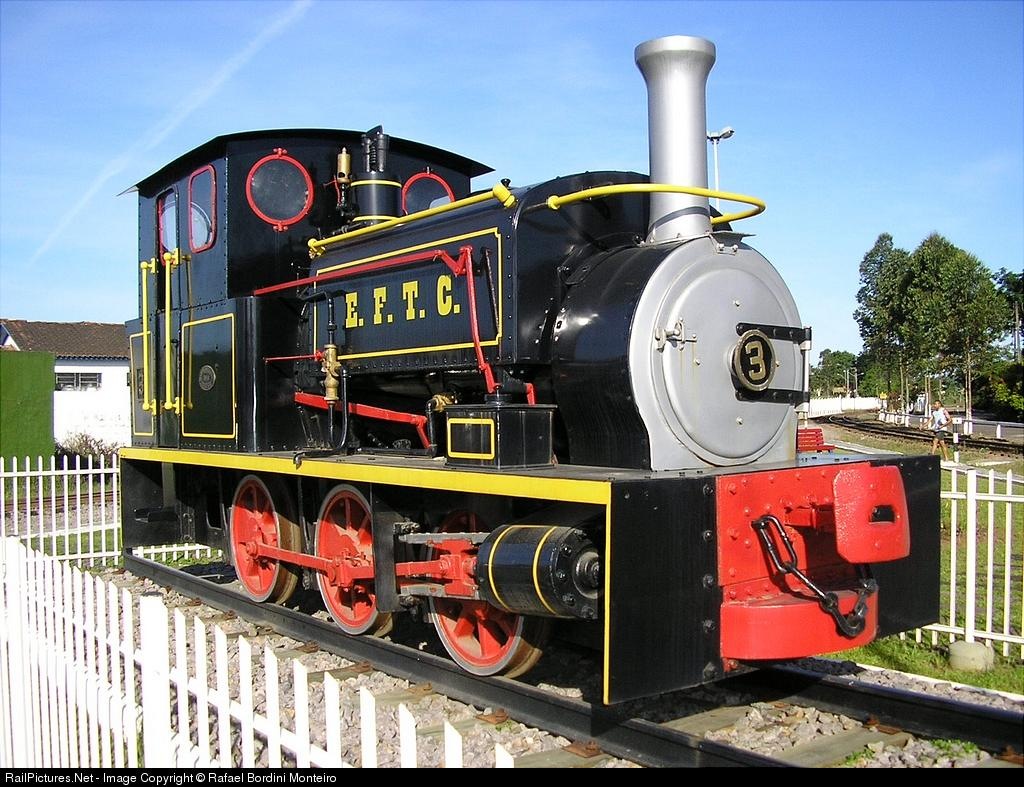
Hunslet 0-4-0ST loco No. 3, Bickerton on the Down afternoon mixed leaving Peckforton station

Rolling stock

The rolling stock on the railway has a variety of origins. Much of the goods stock is freelance, though based loosely on prototypes from the Southwold Railway and the Welshpool and Llanfair Railways. It is assumed that as other railways closed or sold off surplus stock, this railway would have acquired additional stock at bargain prices. (See Railway Stock List)

The locomotives are originally freelance designs and built from kits. These were originally based loosely on various prototypes (ie Andrew Barclay, Hunslet, Peckett and Fowler), but more recently, I have been constructing my own semi-scratchbuilt models based on Southwold Railway originals - namely a 2-4-2T Sharp Stewart and an 0-6-2T Manning Wardle.
The expanding fleet of radio controlled battery powered locomotives
 I have also constructed a couple of battery powered freelance diesel outline locos from kits (see Building an IP Engineering Jessie and Building an IP Engineering Lollypop Railcar) and a semi-scratchbuilt railbus inspired by the Ford Railmotor.
The former Southwold Railway 2-4-2T emerging from the railway's paintshop.

In the past year or so I have migrated from DCC track power to radio controlled battery power (see Getting Started in battery power and an Evaluation of the Deltang Radio Control System)

Operation

Although there are times when will take a train out and simply run it around the main circuit just to see something running, I try to ensure that I run a full, timetabled operating session a few times during the running season (which is usually from late Spring to Early Autumn). (see A Typical Operating Session).
The railbus trundles past the River Gowy on the last Down passenger service of the day
 One of the things I really enjoy is simulating fairly realistic freight operations on the railway. As my model depicts a complete light railway system from terminus to terminus with intermediate stations, I have devised a computer program which generates freight movements for a day's operation (an Up and Down pick-up goods service plus a mixed train in the afternoon). (see Freight Operations on the Railway).
The Up pick-up goods arriving at Peckforton, crossing the Down afternoon passenger train
In addition loaded and empty copper ore trains run throughout the day between the timetabled passenger services. From time to time I also include special Market Day Specials and Bank Holiday Excursion Trains to transport excited tourists up the line to the various attractions. In this way, my train operations are kept realistic but with some variation to maintain interest.
0-4-0T Peckett locomotive No.1 Peckforton on a Market Day Sepcial
 Recently, the railway has had signalling installed to control basic train operations up and down the line. Whilst most Narrow Gauge Light Railways did not employ signalling, I felt that the density and complexity of traffic on my railway would require the installation of semaphore signals to help ensure passenger safety (see How I constructed a set of signals). At present these are manually operated but I am exploring how these might become remotely controlled.
2-4-0T Loco No 2 Beeston awaits the all clear on the approach to Bulkeley station

Future developments

A garden railway is seldom 'finished'. There is always an ongoing catalogue of jobs with varying degrees of urgency on the To-do list. For me, the priorities at this moment are to: