Saturday, April 01, 2017

How I 'Anglicised' an LGB Stainz loco

The LGB Stainz loco which runs on my railway was the first G Scale loco I owned; bought as part of Starter Set back in 1995.
When I abandoned track power, the Stainz was one of the last of my locos to be converted to battery power and radio control (using the Deltang / RC Trains system) - see How I converted my Stainz loco to battery power  but she retained her original shape and colour scheme. All my other locos have been finished in Peckforton Light Railway livery (see Locomotive Update).

Having 'anglicised' all my rolling stock (eg see How I Anglicised an LGB tanker wagon) and constructed my own UK outline locomotives (eg see How I constructed a Southwold Railway Sharp Stewart loco), I felt it was about time I made the Stainz look more UK-based. But where to start?


I roughly sketched out some ideas, principally, extending the side tanks and replacing the spark-arrester chimney - after that I would let my imagination, determination and serendipity guide me.

Disassembly

 Full disassembly of the Stainz loco has been covered elsewhere (eg How I fitted a decoder to my Stainz loco), so I will not go into full detail here. Initially, I only wanted a partial disassembly anyway as I needed to see how the various additions I was making to the loco would look and fit.

From past experience, I know that the whistle on the cab roof is very susceptible to damage and so this was removed by slipping the blade of a screwdriver under the moulding and applying some gentle leverage.

 The motor block was then removed by undoing the four screws which hold it in place and unscrewing the two mountings on the running plate for the valve gear.

The vacuum pump was removed by undoing the screw which holds it in place ........
 .... and the filler for the sandboxes was removed (a push-fit).

I also prised off the mouldings on top of the coal bunkers as these would no longer be needed.

The loco was now ready for the first stage of its reconstruction.

Fitting a running board

 The first job was to remove the rim on the edge of the existing running plate where the new extension would be attached. It was carefully trimmed off on both sides with a craft knife, .....

 ...... and the rivets filled flat.

A cardboard template for the new running plate was measured and cut ........

....... and test-fitted into place - making various adjustments to accommodate existing fitments and mouldings.

 The measurements were then transferred to a piece of 2mm thick plasticard, .........

 ........ which was then cut to shape.

Two additional pieces of 2mm thick plasticard were then measured and cut out (see dimensions below), ............

and the three pieces were then attached to the frames using Plastic Magic solvent. Very few solvent adhesives will bond with the plastic used for LGB loco bodies, but I have found that Plastic Magic is effective. The additional two pieces of plasticard acted as stiffeners and also, as they were recessed slightly, provided additional support for the buffer beam.

After test-fitting the motor block I realised that, if I wanted to retain the valve gear, I would need to cut holes in the running plate for their upper supports. [You will notice also that my measurements were not entirely accurate for the two support pieces and so some Gorilla Glue was used as a filler].

The supports for the valve gear were then screwed into place (and offcuts of 2mm plasticard glued to span the joint between the old running plate and the new, to reinforce the joint).

The side tanks

I now turned my attention to extending the side tanks. Card templates were cut for the outside of the tanks on each side. The length of the new tank sides coincided with the joint between the boiler and the smokebox as this also happened to be slightly longer than the 18650 li-ion batteries which I intended to fit into the tanks.

The dimensions were then transferred to pieces of 2mm thick plasticard.

The edges which were to abut to the existing tanks were chamfered to enable a flush-fit.

 The inner sides of the tanks were then cut to size, with recesses to accommodate various mouldings.

 Two pieces of 2mm think plasticard (30mm x 48mm) were then cut ........

..... for the front of each tank. These were glued into place and 15mm wide pieces of plasticard fitted into place at the lower front edge of each tank for reinforcement and also to allow the tanks to be screwed to the running plate.

The tops of the tanks were then cut out (101mm x 30mm) from 1.5mm thick plasticard ......

.... and attached.

For each tank, two 5mm wide strips of 2mm thick plasticard were cut out .......

...... and glued into place into the front corners of each tank.

The tank extensions were then glued to the existing tanks with Plastic Magic solvent.

The outside leading corners of each tank were rounded with a file and filler (Squadron Products White Putty) applied.

Filler was also applied to the joints between the old and new tanks.

Once hardened, the filler was sanded smooth.

I decided that some of the existing rivet detail would be sacrificed at this stage to make sanding easier. Rivets would need to be applied to the tank extensions anyway and so replacing the rivets would not require too much additional work.

The revised upper body was then test-fitted to the running plate and the motor block fitted back into place ......

...... to check clearances.


Buffer beam

A 2mm thick piece of plasticard was cut out (105.5mm x 24mm).

Curved cut-outs were made in each side (see dimensions below) ........

..... and a slot cut for the couplings.

The buffer beam was then glued to the front of the running board .......

...... and the  gaps between the frames and the beam filled with suitably sized and shaped pieces of 2mm plasticard.

A 15mm square of 1.5mm plasticard was cut out and a hole, 4mm from each edge was made to fit over the moulding for the centre coupling. This was glued into place on the buffer beam.

The boiler

I now looked closely at the boiler. I decided that the dome and other paraphernalia looked a bit too Germanic and needed to be removed.

This major surgery was achieved with a craft knife.

The boiler was now not a pretty sight and so I needed to find some way of plugging the gaps.

Offcut strips of 1.5mm thick plasticard were glued into place inside the boiler, ......

...... which gave some support for the infill.

Pieces of 2mm thick plasticard were cut to fill the holes and glued into place .......

...... and then smeared with filler.

Once dry, the filler was then sanded smooth(ish). However, I wasn't confident that the top of the boiler would look flawlessly smooth once it was painted and so.........

...... a 1.5mm thick plasticard wrapper was cut to size, .........

...... wrapped around a piece of broomstick and held in place with cable ties ..........

..... and then plunged into a pan of boiling water an left for five minutes before being removed.

The wrapper was then glued to the boiler .......

.... using Plastic Magic solvent and temporarily held down with cable ties until the solvent had done its job.


The chimney

The old spark-arresting smoke stack needed to go. I did contemplate using the LGB replacement but as it cost around £20 and included a smoke generator which I wouldn't be using, I decided to make my own.

The chimney was cut in half carefully with a razor saw .....

..... just below the smoke generator.

.... which left me with the lower half of the chimney.

The plastic barrel from a freebie ball pen of the right diameter was unearthed.

Its cap proved to be a tight fit in the chimney moulding

The barrel of the pen was then cut to length and attached to the lower part of the chimney.

Three strips of 0.5mm thick plasticard were cut, approximately 1.5mm, 1mm and 0.5mm wide and 50mm long.

These were then glued to the top of the chimney in overlapping layers.

Filler was then applied ........

and smoothed down with a needle file and fine emery paper.

.... and the chimney given a couple of coats of primer and satin black - using Halford's rattle-can aerosol sprays.

Painting and finishing

After covering the inside and the roof of the cab with masking tape, the main body was given a couple of coats of Halford's grey primer.

Once this had dried and hardened, filler was applied where the finish looked less than perfect.

This was smoothed down with fine emery.

 The tank sides were marked out for the rivets - using the same spacing as on the original loco tanks.

Cambrian Models plastic rivet heads were then painstakingly applied using solvent to fix them in place.

The body was then given another couple of coats of grey primer, followed by a couple of coats of Rover Brooklands Green using Halfords rattle can aerosols.

The frames were given a couple of coats of primer and then rivets were applied to the sides of the running plate.

 The frames were then given a couple of coats of satin black ........
 
..... and the boiler a coat of grey primer before having 1mm thick and 3mm wide plasticard boiler bands glued on with solvent.

Another coat of primer was then applied, followed by two coats of Rover Brooklands Green.

The wheels were given a clean to remove excess grease and oil .......

.... before the treads and flanges were covered in masking tape.

They were then given a couple of coats of grey primer, followed by two coats of satin black.

Once the paint had dried, the masking tape was removed .........

....... and the wheels and motion fitted back into the motor block before being attached to the frames.

The Electrics

 The three 14500 batteries and protection board which originally powered the loco (see How I converted a Stainz loco to battery power) were removed.

 .... and the wiring diverted to where the new side tanks would be.

 Three 18650 li-ion batteries were wired in series and fitted into the new side tanks.

 ..... and the battery protection board soldered into the circuit.

Holes were drilled in the insides of the tanks and cable ties passed through.

The batteries were then held in place with the cable ties.

A Dallee steam soundcard was then wired into the RC Trains / Deltang Rx65b receiver (positive and negative feed from the battery, two wires to the motor output from the Rx and one wire to output C for triggering the whistle with the bind button).

The roof was removed from the cab by unscrewing the four screws holding it in place ......

.... revealing the LGB soundcard circuit board .......

...... and speaker.

 This was replaced with a 50mm 8ohm speaker which was glued into place.

The circuit board and switch inside the firebox........

..... was removed by unscrewing the two screws holding the switch in place.

The wires from the speaker were then threaded through into the firebox.


 Cut-outs were removed from the base of the backplate to allow the wiring from the batteries to pass through.

and the wiring from the batteries and speaker fitted with JST plugs so the wiring in the body could be connected to the wiring attached to the frames.

The soundcard and the receiver were then attached to the footplate with a cable tie.

I did consider putting the soundcard and receiver inside the boiler in place of the LGB circuit board, but this would have meant the potentiometers on the soundcard would have been inaccessible and so the volume and chuff tempo could not be adjusted without dismantling the loco. For more information on how I connected the Dallee soundcard to the RC Trains / Deltang Rx65b see How to interface soundcards with Deltang receivers

I made four loco lamps fitted out with 5mm LEDs; two red/white bi-colour and two warm white (see How I constructed some loco lamps).

 The lamps were fixed in place on the loco body and running plate and the wiring connected to the receiver output pads.
The lower front lamp was connected to output pad A on the Rx65b. This provides an automatic front light and also mirrors the LED on the Rx to show, for example, when the Rx is hunting for the transmitter signal (1 second flashes) or when the Rx has gone into bind mode (rapid flashes). The remaining lamps were connected to output pad 1 (auto forward lighting) and output pad 2 (auto reverse lighting). This was because the upper lights are bi-colour LEDs and have a common cathode (negative) lead which needed to be connected to the negative supply from the battery. For more information on using Deltang receiver pads see Using  output pads on Deltang receivers

Final assembly and detailing

Before doing the final titivations, I took her outside into the garden for a test run.


Having proven that she would run satisfactorily, I then took her back into the workshop for a few more embellishments.

A brass dome (from Swift Sixteen), had already been added .....

.... and the chimney cap had been painted with brass enamels.

The head and tail lamps had also been added .........

 ...... so that the uppermost lamp glowed white or red dependent on which direction the loco was travelling and the lowermost lamp just glowed white when it was leading. See How I made some loco lamps.

Whitemetal castings of tank filler caps from Garden Railway Specialists were glued to the tank tops after having been primed and painted Halfords Rover Brooklands Green.

A whitemetal casting of safety valves (again from GRS) was painted and installed on the boiler and a brass whistle (from Roundhouse Engineering) was glued into the hole on the cab roof in place of the LGB 'gold plated' one.

As one of the plastic grab-rails had become damaged when it was being removed, I made a couple of replacements from brass rod and brass washers. The remaining LGB black plastic grab-rails were painted with brass enamels to match the new ones.

A smokebox door handle was made from three pieces of brass rod and a plastic boss which I found in my 'plastic bits' box. This was painted matt black and glued into place.

To cover various holes left in the front and rear of the cab which originally held the LGB lamp, safety valve and lighting socket .........

..... three rectangles of 1mm thick plasticard were cut out and given plastic rivets ........

.... painted with primer and Brooklands Green and then glued into place over the holes.

 Name and number plates from Narrow Planet and Roundhouse Engineering were glued to the tanks .....

..... and to the cab sides.

 Finally, a driver from Design Scan Print 3D (with legs shortened to enable him to fit) was given a couple of coats of grey primer and then dry-brushed with acrylic paints.

 He was then glued into place inside the cab .....


 ..... and a piece of black Gaffa Tape was fixed over the Rx and soundcard to disguise their presence.

After some deliberation, I decided to remove the valve gear from the motion. It looked out of place on a UK loco. Small silver washers have been positioned beneath the bolts holding the connecting rods in place so that, if ever I change my mind, the valve gear can be re-instated.

 The loco was then admired (taking care not to focus on the various flaws, faults and anomalies which have cropped up during construction!).

I feel she has some similarity with the Welshpool & Llanfair Railway's Beyer Peacock locos (minus the Walschaerts valve gear) and so I feel happy that she is now quite clearly a UK inspired loco.

There is still a little more work to do - maybe a handrail on the smokebox, numbers on the buffer beams (which could be painted red) and some light weathering. However, I am very pleased that No.10 (Tiverton) is now ready for service and all I need is some finer weather to give her an opportunity to demonstrate her prowess.

Update 

Here she is - taking part in her first full operating session:


Thursday, March 30, 2017

A quick introduction to batteries for model trains

Introduction

This page is designed to be a fairly simple and straightforward introduction to battery power for model trains. It is by no means a comprehensive or definitive guide. Hopefully there will be enough here to get you started and answer some of your basic questions.

I've covered the following:

Cells, Batteries or Packs - what's the difference?

To be pedantic, a battery is a collection of individual cells wired together - ie a 'battery' is really a 'pack' of 'cells'. However, it has now become common parlance to refer to 'cells' as 'batteries' so, when we refer to an AA 'battery', we are really describing a single 'cell'.

In this posting, will use both 'cell' and 'battery' to refer to cells, but will use 'pack' to refer to an interconnected collection of cells.

Disposable or rechargeable?

Disposable (or Primary) batteries

This is the simplest way to power your locos - insert some batteries into a battery box, connect the box through a reversing switch to your motor and away you go!
To be able to reverse the direction the loco travels, the DPDT (Double Pole Double Throw) switch would need to be wired-up like this:

When the switch is moved to the right, the motor leads are connected directly to the battery leads
and when it is moved to the left, the motor leads are swapped over, thus reversing the motor.

Types of disposable battery

The most effective disposable batteries for use in model trains are alkaline batteries. They are now the most readily available and tend to last longer than zinc carbon batteries. However, with more recent developments in battery technology, disposable lithium batteries are now becoming more common, though their price makes them less competitive than alkaline.
Zinc-carbon, also known as carbon-zinc or the Leclanché battery. These are the earliest and least expensive sorts of primary batteries. They deliver 1.5 volts but their capacity tends to be lower than alkaline batteries (ie they do not last as long before becoming depleted)

Alkaline. (Alkaline-manganese), is an improved version of the zinc-carbon battery and also delivers 1.5 volts. Generally longer-lasting than zinc-carbon and less prone to leakage.
Lithium (Lithium iron disulfide (Li-FeS2)) Normal lithium primary batteries deliver three or more volts, but Li-FeS2 batteries are usually rated at 1.5 volts to be compatible with AA and AAA formats. They are most often found as button cells (eg for use in hearing aids) but have a much longer life cycle than alkaline batteries (eg a heart pacemaker battery can last up to ten years). They are becoming more readily available and are beginning to drop in price. Some airlines do not allow any type of lithium battery to be carried on board planes.

Rechargeable (secondary) batteries

Rechargeable batteries can be used directly in place of disposable batteries, using the same wiring diagram as above. However, the batteries would need to be removed from the battery box to be charged. Alternatively, the batteries can be left in the loco and charged in-situ. If the  DPDT reversing switch does not have a 'centre off' position, an SPST (single pole, double throw) switch must be included in the circuit to switch between the motor circuit and a charging socket - to help ensure that the loco is not left on while it is being charged. 

As an additional precautionary measure, I usually use 2.1mm DC power sockets for charging which include an isolation switch. 


 When a plug is inserted into the socket, the connection between the battery and the motor (the blue wire in the above diagram) is cut-off. 

There are four main types of rechargeable battery available 'over the counter - Nicad/NiCd (Nickel Cadmium), NiMh (Nickel Metal Hydride), Lithium and Lead Acid. Nicads have now largely been replaced by NiMh. Lithium batteries are available in an increasingly baffling range of sub-types but are becoming a lot safer and more reliable. Lead acid batteries, as the name suggests, tend to be quite heavy and bulky.

I used to use NiMh batteries but now use lithium-ion batteries. These provide more power for their size than NiMh, but need to be handled with care.

NiCd (Nicad - Nickel Cadmium) batteries were once the recommended rechargeable battery for models but they have largely been superseded by NiMh (Nickel Metal Hydride) batteries. NiCads are becoming increasingly difficult to find. Each battery delivers 1.2 volts.

 NiMh batteries do not suffer from the 'memory effect' which plagued NiCads - they can be recharged at any time, without the need to be fully discharged. As with NiCads, NiMh cells deliver 1.2 volts.


A major disadvantage of ordinary NiMh batteries is that they slowly become depleted when stored. It can be very frustrating to take your loco out into the garden only to find it needs recharging. Low Self Discharge (LSD) NiMh batteries (also known as Eneloop) overcome this problem. They tend to be slightly more expensive than ordinary NiMh batteries but, to my mind, they are well worth the extra expense.
Lithium-ion (Li-ion) and Lithium-Polymer (Lipo) are now being used more extensively but many modellers are cautious about using them as, if not handled correctly, they are more volatile and can burst into flames. Their main advantage over other sorts of rechargeable battery is their capacity. Whereas each NiMh cell delivers 1.2v, each lithium cell delivers 3.7v. Hence, li-ion and lipo batteries take up considerably less space inside a loco than NiMh batteries. 

 Li-ion batteries are inherently more stable and reliable than Lipos because of their chemistry and their construction. They are available in a range of cylindrical styles:

By far the most popular is the 18650 sized battery (18mm diameter x 65.0mm long). Most laptop computer battery packs comprise three or six 18650 li-ion cells, giving 11.1 volts. 14500 batteries (14mm diameter x 50.0mm long)  are the same size as AA cells.

Because of their durability, range of sizes and slower discharge rates, li-ions are better suited to battery powered locos than lipos. 

 Lipo batteries are generally favoured by model car and model plane enthusiasts because they are capable of delivering large bursts of power and can be recharged more quickly. However, these capabilities can make them less stable than cylindrical li-ion batteries. Lipos are generally constructed into flexible plastic pouches ........

.... though sometimes they can be further encased in rigid cardboard or plastic cases but generally retain their cuboid shape:

 Small sealed lead acid batteries, such as those used as back-up batteries for burglar alarms, can be used inside large scale locomotives but their major disadvantage is weight and size. 


 Their advantages are the ease with which they can be recharged and the relative simplicity of their wiring. 

Battery capacity

The capacity of rechargeable batteries is measured in Amp Hours (Ah) or MilliAmp Hours (mAh). For example, this NiMh battery is rated at 2600mAh (or 2.6Ah).

In theory, roughly, this means that if the electric motor which powers your loco is drawing 1 amp, then a 2Ah (or 2000mAh) battery should be able to power it for two hours. However, many other factors will affect this rating and so it should be taken only as a guide. Furthermore, many of the cheap, 'bargain' batteries which  are offered for sale on eBay exaggerate their capacities. For example, a set of li-ion batteries which I bought cheaply on eBay were advertised as having a capacity of 3200mAh. I discovered their actual capacities were closer to 1600mAh - and one of them ceased working after less than a year and only three charges.

Ideally, you should choose the batteries with the highest Amp Hour rating you can squeeze into the available space in your loco. Larger batteries, as you would expect, tend to have higher capacities.


Battery packs

Ready-made battery packs can be purchased from specialist suppliers such as Strikalite, who will construct battery packs to your own specifications. However, it is possible to make your own.

Connecting batteries in series

When batteries are connected in series, the output voltage is increased in proportion to the number of cells in the pack. For example, three 1.2v NiMh batteries connected in series will give an output of 
3 x 1.2v = 3.6v.

If the three cells are li-ion, then the voltage of the pack would be:
3 x 3.7v = 11.1v

If the cells were alkaline disposable batteries the the voltage of the pack would be:
3 x 1.5v = 4.5v

However, the capacity of the pack would be the same as for one of the cells. For example, if the pack was made from three 1500mAh NiMh cells then the capacity of the whole pack would also be 1500mAh

It is not advisable to mix batteries with different Ah ratings in the same pack. You should only connect batteries of the same type together into packs - and in the case of Li-ion batteries, they should preferably be from the same manufactured batch to ensure the charging and discharging characteristics are the same as these can vary with the age of the battery.


Connecting batteries in parallel

If batteries are connected in parallel, then the overall voltage of the pack will remain the same as for one cell, but the capacity of the pack will increase. For example, if three 1500mAh NiMh batteries are connected in parallel, then the voltage of the pack will be 1.2 volts but the pack's capacity will be:
 3 x 1500mAh = 4500mAh
 Just as the pack of three cells in series is designated as 3S, a pack of three cells in parallel is designed as 3P


Composite packs

A 3S2P pack would comprise of six cells - three pairs of parallel wired cells in series. In other words, pairs of cells are wired in parallel and then the three pairs are connected in series:
As you can see, a 2S3P pack would comprise two sets of three cells connected in parallel, wired together in series.

Let's assume that the each cell in the packs above are 1.2v, 1200mAh NiMh. 
  • The output from the 3S2P pack would be 1.2v x 3 = 3.6v, 1200mAh x 2 = 2400mAh  
  • and the output from the 2S3P pack would be 1.2v x 2 = 2.4v, 3 x 1200mAh = 3600mAh.
So, the 3S2P arrangement would be used for a higher voltage, lower current motor  and the 2S3P for a lower voltage, higher current motor.

For more information on wiring up battery packs see - http://scriptasylum.com/rc_speed/lipo.html

Choosing the right sized pack for your loco 

 It can be quite confusing trying to decide what size of battery pack you need for your loco. For example, most of my battery locos use commercial motor blocks designed for track-powered locos running off a maximum of 24v. However, because I don't require express train top speeds, I use 12v battery packs. My modelling mate in Australia also uses 24v motor blocks and most of his locos are happily powered by 9.6v packs and has some powered with 7.2v packs.

Before cramming every nook and cranny in your loco with batteries, try out a few different configurations of battery pack sizes to determine what sort of top speed you want for your loco. There is not point in having an excess of volts if you never use them.
 

Battery protection

It is very important that lithium cells are protected with electronic circuitry to ensure they are not short-circuited or are over-charged. Most importantly, lithium cells must not be overly discharged. If their voltage level falls below 3 volts then the cells can become permanently damaged. Some li-ion batteries include miniature protective circuity to prevent this and are sold as 'protected' batteries. 
 However, individual 'protected' cells cannot be connected in series to form larger battery packs, 'Unprotected' li-ion cells can be connected into packs but it is highly advisable that protection circuit boards are used.

The wiring for the board is fairly straightforward. The board needs to monitor the condition of each battery in the pack and so connections need to be made between the board and the ends of each battery.
 Two further connections are then made from the board to the wiring and the charge socket in the rest of the loco as normal. 


Although the convention is for a two way switch to be used in locos to switch between powering the loco and connecting the batteries to the charge socket for charging, it is not essential. A simple on-off switch will suffice, provided you remember to turn the loco off when charging. One advantage of having the charge socket 'live' at all times is that a meter can be plugged into it to monitor voltage flow when the loco is in motion.

Charging batteries and battery packs

It is vitally important that you use the correct type of charger for the batteries you are intending to charge. A charger designed for NiMh batteries should NEVER be used to charge li-ion batteries and vice versa.

If your batteries can be removed from the loco then a standard 'wall' charger can be used provided you ensure that it is compatible with the type of battery which you are charging. 


If you are charging batteries and packs inside your loco then you need a charger which is specifically designed to charge the type of battery and the size of pack you are using. For example, if your loco is powered by a pack made up from three NiMh cells wired in series, then you need a charger capable of charging a 3.6v NiMh pack, such as this one which is designed to charge NiMh packs from 3.6v (3 cells) up to 12v (10 cells):

It is an 'intelligent' Delta charger which senses the state of charge of the cells and will automatically go into trickle charge mode when the batteries reach their full charge. As can be seen, it includes a range of connectors making it fairly universal.

Similar chargers can be bought for charging lithium-ion packs and lead acid batteries.

For maximum flexibility, I would recommend the iMax B6 charger. This is capable of intelligently charging NCad, NiMh, Li-ion and lead-acid batteries. It seems to have become the most popular smart charger available and as a consequence has dropped in price. Its disadvantage is that it looks very complicated to use when it is first taken out of the box, compounded by a largely incomprehensible handbook, but one its basic features have been grasped it is surprisingly easy to use and is very versatile. (see A Quick Introduction to the iMax B6 charger)

These can be purchased quite reasonably on eBay. I prefer the original version of the charger as Version 2 requires obligatory connection of a balance charge lead when charging li-ion batteries.

Balance Charging

Balance charging ensures that the level of charge in each cell in a pack is the same. If the charge becomes unbalanced then the efficiency of the pack is reduced. If the imbalance becomes too acute then the cells can become damaged beyond repair and so it is advisable to balance charge any pack from time to time. Again, the wiring for this is fairly logical - just as the protection board needs to be able to monitor the condition of each pack, the charger needs to do the same. Consequently, the connection to a charge plug - usually a JST multi-pin plug - is the same as that needed for the protection board.


The loco is then connected to the charger through an additional balance charge lead....

....connected to the balance charge sockets on the side of the charger.
Once in balance charge mode, the charger will automatically sense and manage the charging of each individual cell.

 Controlling speed

Manual controllers

A manual speed controller uses a potentiometer to adjust the voltage supplied from the battery to the motor. You could use a wire wound potentiometer to adjust the voltage, but there are more elegant and efficient ways to control the speed. Speed controllers can be bought in kit form from online suppliers such as IP Engineering or Cambrian Models or, if you are competent with a soldering iron, then you can make your own using a potentiometer and a single component such as the IRF3205 MOSFET (Metal Oxide Semi-conductor Field Effect Transistor).

 You may need to bolt the MOSFET to a heat-sink (eg a small piece of aluminium sheet) if the motor is put under a moderate load as it will generate heat which will need to be disipated.

Alternatively, you can buy a PWM (Pulse Width Modulated) motor controller circuit board quite reasonably on eBay, such as this:


The speed control knob can be disguised as a chimney, brake handle or wheel, or even a bucket.

Radio control

Radio control enabled you to control the speed and direction of your loco remotely from a distance. More sophisticated radio control systems allow you to control additional features such as lighting, sound and other gadgets such as remote uncoupling.

A traditional radio control system uses a transmitter, receiver and an electronic speed controller (ESC).

Most ESCs designed for model railway locos control speed and direction (eg Brian Jones' Mac5)


or the MTroniks Viper 10 Loco,

 - but some of the less expensive ESCs control only speed and so a separate radio controlled direction switch is needed. If looking for low-cost ESCs, make sure you buy one advertised as controlling 'brushed' motors.

Any standard radio control system can be used to operate the loco. I have used a cheap transmitter designed for use with those tiny battery powered helicopters and a standard receiver, into which is plugged the ESC (in this case a Brian Jones Mac5)

It is possible to get receivers which have an ESC built-in (eg the Deltang / RC Trains Rx65b).


These tend to be more compact and so will fit into smaller locos (eg the IP Engineering Plate Frame Simplex) and. of course, the wiring is simplified.

Radio control systems designed for use with model trains

 The disadvantage of standard radio control systems is that they are primarily designed for use with model planes, boats or cars and so tend to have joysticks or levers to control speed. If the joystick is sprung-loaded then a finger or thumb has to be held on the joystick continuously while the loco is in motion. Fortunately, there is a range of radio control systems available designed specifically for model trains. Here is a small selection:

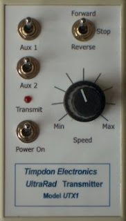
Timpdon Ultrarad
http://www.timpdon.co.uk/timpdon/telec/products/products_urc.php

RC Trains / Deltang
http://rctrains.co.uk/Transmitters.htm

Yatton Engineering / Deltang
http://www.yattonmodelengineering.co.uk/radiocontrolsystem.html

LocoLinc

http://www.locolinc.com/locolinc.html

I have only had direct experience with Deltang and RC Trains equipment and also, as I used to construct and sell RC Trains transmitters, it would be unfair of me to offer opinions on the relative merits of each system. Over the years (well before I set up RC Trains), I have accumulated considerable knowledge of the Deltang system - just enter Deltang into the search box at the top of the page or browse through the radio control section in the blog contents for more information.

For general information on radio control in large scale garden trains see my blog entry on getting started with radio control.